Ademco 8DL5805BDV-1 Key fob Security Transceiver User Manual new srr fcc sub rev 1
Honeywell International Inc. Key fob Security Transceiver new srr fcc sub rev 1
Ademco >
II with FCC Part 15 statment
EXHIBIT 7 USERS MANUAL / OPERATING INSTRUCTIONS CFS8DL5805BDV-1
SECTION 2.1033 (1a)
SECTION 2.1033 (1a)
Information to User - FCC Part 15. To be included in the user’s manual/operating instructions.
Part 15.21 Statement for all intentional and unintentional radiators shall be included.
“ This device complies with Part 15 of the FCC Rules. Operation is
subject to the following two conditions: (1) this device may not cause
harmful interference, and (2) this device must accept any interference
received, including interference that may cause undesired operation. “
PLEASE SEE THE II
( Installation Instructions )
ON THE NEXT 4 PAGES.
K5756 2/05 Rev. A
ADEMCO 5805BDV
TWO-WAY WIRELESS KEY WITH VOICE
INSTALLATION AND SETUP GUIDE
General Information
The 5805BDV is a four-button wireless key that permits
the user to control the alarm system remotely. It is a two-
way device that sends commands (e.g., Arm, Disarm, Panic)
to the alarm system, and receives current status from the
system. Additionally, the unit contains a Message Mode
that allows the user to leave or retrieve voice messages.
One bi-color status LED and a speaker indicate status.
Each button can be programmed for any zone response
type, but is typically used for arming, disarming, panic, and
output relay operation.
1. The 5805BDV can be used in conjunction with
the following:
• 5800TM (Transmitter Module) and a 5881 or
5881EN receiver
• 5883 transceiver
• 6128RF, 6150RF, or 6160RF
keypad/transceivers
• Lynx control panel.
2. Place one of the receivers mentioned in 1 above
and the Transmitter Module in a high, centrally
located area for best reception. The 5800TM
module must be located between 1 and 2 feet
from the receiver.
The unit is powered by a single, replaceable, AAA, Alkaline
battery. The battery is supplied with the unit but not
installed (see “To Install/Replace Battery” for more
information).
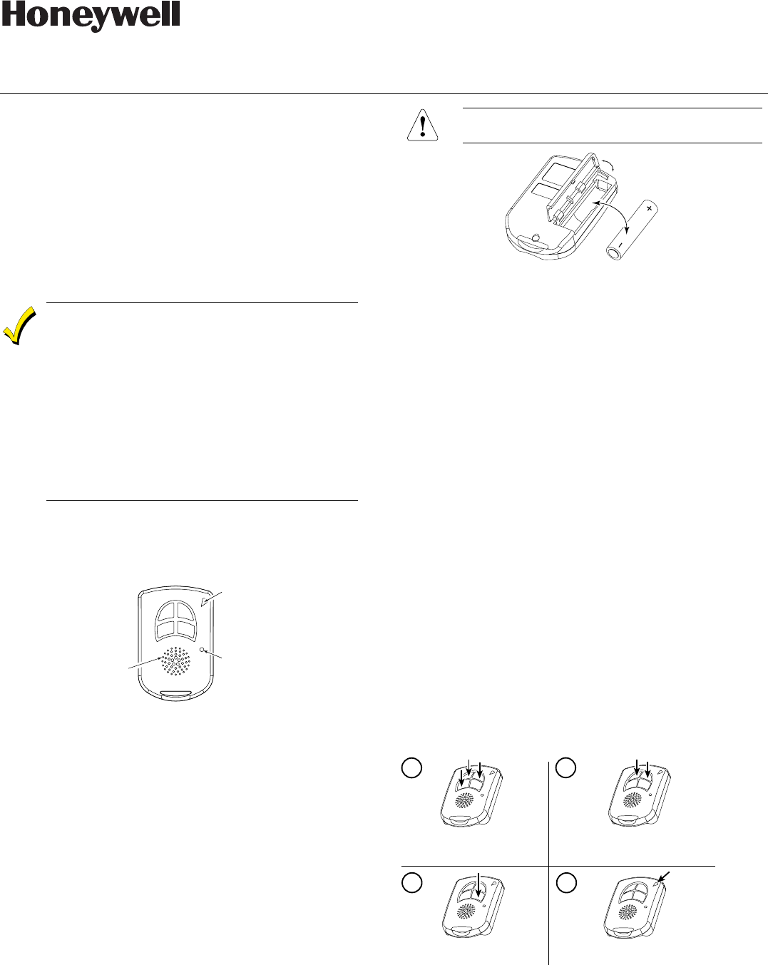
5805BDV-001-V0
Speaker
LED
Microphone
ON OFF
12
5805BDV Front View
Loop Assignments:
• ON Button = Loop 3 • OFF Button = Loop 2
• 1 Button = Loop 4 • 2 Button = Loop 1
To Install/Replace Battery
1. On backside of unit, press the battery door down, then
push forward and pull up. NOTE: Be careful not to
activate any buttons while doing this.
2. Remove the old battery.
3. Either wait 20 seconds, or press and release any button
on the unit.
4. Place the AAA battery into battery compartment (see
diagram).
Observe polarity to prevent damage to the unit or
to the battery.
5805BDV-002-V0
After the new battery has been installed, you will get a
confirmation tone within five seconds.
Programming the 5805BDV House ID
You must program a House ID number into the unit before
you can use it to display the system status. The House ID
number, in the range of 01 to 31, must be the same as
the one used in the control panel for each device. The
default House ID of the 5805BDV is 10.
To Program a House ID
1. Enter Programming mode by pressing the ON, OFF, and
1 buttons at the same time. You will get an audio
announcement stating “House ID Mode” with the
LED flashing red and green alternately.
2. Enter the House ID number by using the ON button to
enter the 10’s digit and the OFF button to enter the 1’s
digit.
Refer to the four examples below.
NOTE: If the digits entered are not within the range of
01-31, the unit will not accept the entry.
3. Accept the entry entered by pressing the 2 button.
4. The unit displays the stored number by flashing the red
LED for the 10’s digit and flashing the green LED for the
1’s digit (e.g., for House ID 21, the red LED will flash
twice, the green LED will flash once).
5. The unit will then automatically exit the House ID
programming mode.
6. If you enter an incorrect House ID, you must start again
from step 1 above.
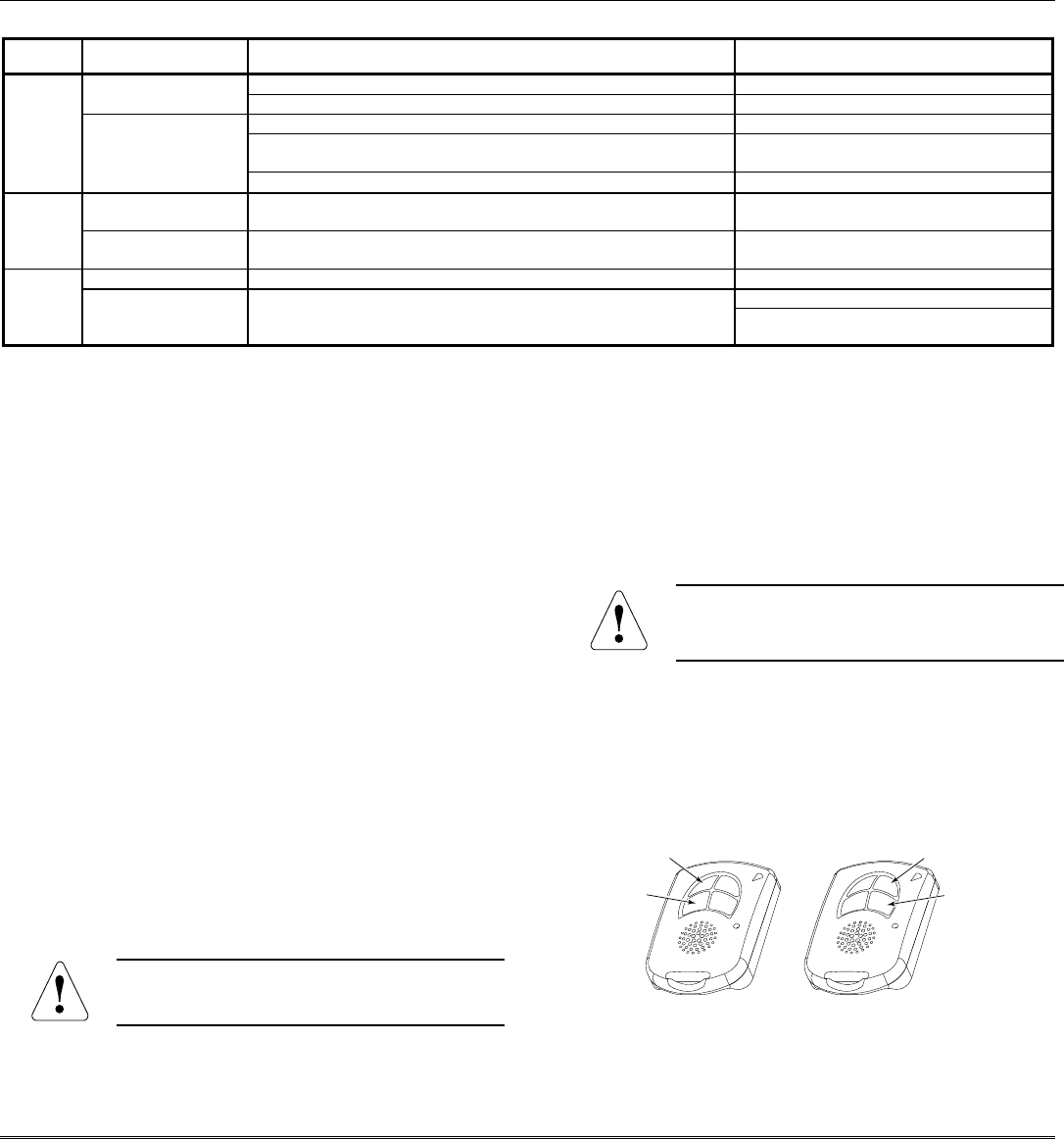
Example: To enter House ID # 17 into the unit:
5805BDV-003-V0
Enter House ID mode: Press ON +
OFF + 1 buttons until LED flashes
House ID will be shown by flashing LED.
Unit automatically exits House ID mode.
To accept entry, press 2 button.
Enter
House ID
#17: Press & release ON
button once, press & release OFF button
7 times.
12
4
3

- 2 -
To View the House ID
1. Enter Programming mode as described in step 1
(previous page).
2. Depress the 2 button to view.
The unit displays the stored number as programmed on the
previous page (step 4), then automatically exits
Programming mode.
Programming a House ID in the Control Panel
• On VISTA-40 control panels and above, use Device
Programming mode to enable the RF receiver and enter
the House ID number.
• On VIA-30 control panels and below, go to field ✶24 and
enter the House ID number.
Programming the Buttons
Each 5805BDV is assigned a unique serial number during
manufacture. Each button on the unit also has a unique
“loop” number that must be programmed into the control
panel during installation. Assign each button to an
individual zone number and program the Input Type as BR
(Button Type RF) by entering 5 in the control panel’s Zone
Programming mode.
Then, input the serial number by one of the following
methods:
• Transmit twice from the device by pressing one of the
buttons when prompted for the serial number.
• Enter the serial number manually through the keypad.
• Enter the serial number through Compass downloader
software as applicable.
Be sure to include the loop number of each button during
programming (see loop assignments on previous page).
NOTE: Do not use the 5805BDV for 24-hour silent alarm,
as the unit itself is not silent.
Button 1
If you choose not to use Button 1, you must do the
following to avoid a “CHECK” condition when the button is
accidentally pressed:
1. Assign this button to a zone.
2. After the serial number has been programmed, re-
enter Zone Programming for that zone.
3. At the “Zone Type” prompt, enter 00 and press [✶].
a) On VIA-30 control panels and below, the system
will ask whether you want to permanently delete
that zone. Enter 0 (No). This will cause the
system to retain the serial number, but render the
button inactive.
b) On VISTA-40 control panels and above, continue to
press [✶] until you see the “Enter Zone No?”
prompt again. At this point, Press 00 and [✶].
Then press ✶99 to exit Program mode.
On VISTA-40 control panels and above
If a button is assigned to zone type 20 (Arm Stay), 21 (Arm
Away), or 22 (Disarm), you must assign a user to the button
in order for it to operate. Proceed with the following steps.
To assign a user number to an Arm/Disarm button:
1. Enter [4-digit User Code] + 8 + [User No.] + [4-digit new
User Code].
2. Answer Yes or No to the “Open/Close Report?” question.
3. Answer Yes to the “RF Button?” question.
4. Enter the zone number assigned to the Arm/Disarm
button. The keypad will show the summary of user
information on its display.
5. Test the Arm/Disarm button to make sure it operates
correctly.
Activating High-Security Mode
In order to activate the 5805BDV wireless key in High-
Security mode, you must use an encryption-capable 5800
Series receiver or transceiver.
1. Program the 5805BDV in Zone Programming mode as
usual.
2. After programming the unit, exit Zone Programming
mode.
3. Enter Go/No Go Test mode at the control panel (see the
control panel Installation Instructions for specific
information.)
4. Press and hold the ON, 1, and 2 buttons at the same
time. You will get an audio announcement stating
“Encrypted Mode On” with the LED flashing red and
green alternately.
5. The 5805BDV transmits a special signal to the receiver.
After 2 seconds, the unit will shut down. The 5805BDV is
now in High-Security mode.
Deactivating High-Security Mode
Press and hold down the OFF, 1, and 2 buttons at the same
time. You will get an audio announcement stating
“Encrypted Mode Off” with the LED flashing red and green
alternately. After 2 seconds the 5805BDV will shut down and
is no longer in High-Security mode.
Adjusting Volume Level
This unit is shipped with the volume set to the lowest level.
To adjust the volume, proceed as follows:
1. Enter the Volume Level Programming mode by pressing
and holding down the ON, OFF, and 2 buttons
simultaneously until the LED flashes red.
NOTE: If no button is pressed for 5 seconds, the unit will
automatically shut down and no change to the volume level is
made.
a. Press the 1 button for low volume level, or
b. Press the ON button for medium volume level, or
c. Press the OFF button for maximum volume level.
The word “CHECK” will be heard for the volume level
adjustment.
2. Press the 2 button to accept volume setting.
Volume level setting affects the life of the battery.
Use low volume for maximum battery life.
- 3 -
To Record a Message
1. Press and hold down the 1 and 2 buttons for two seconds.
You will get an audio announcement of “Message Mode.
NOTE: If the Red LED is flashing and you hear “Check
Message,” there is a recorded message that must be
played back before you can record a new message.
2. Press and release the ON button and begin speaking into
the microphone if you want to record up to a 20-second
message. To stop recording, press/release the OFF button.
To Playback a Message
1. Press and hold down the 1 and 2 buttons for two seconds.
You will get an audio announcement stating “Message
Mode—Check Message” with the Red LED flashing.
2. Press and release the 2 button to playback the message.
To Activate a Function
To activate a function, press and hold down the appropriate
button until a single beep is heard and the LED alternately
flashes RED and GREEN, and then release.
System Status Indications Table
LED LED Condition Voice Announcement System Status
System Armed Away Armed Away or Maximum On Steady
System Armed Stay Armed Stay or Instant
Fire, Zone (Faulted Zone Number or Zone Descriptor) * Fire Alarm in progress
Alarm, Zone (Faulted Zone Number or Zone Descriptor) * Armed, Burglary Alarm in progress, or
Alarm Memory
Red
Flashing
In Set Volume Level Mode
On Steady System Disarmed
Ready To Arm
Disarmed, Ready to Arm Green
Flashing System Disarmed
Not Ready To Arm
System Not Ready, System Trouble
Flashing Silent Indicates RF transmission
In Programming Mode (Installer use)
Red &
Green
Alternately
Flashing
Silent
In Enable or Disable Encryption Mode
* Zone descriptors will be annunciated only if the receiver is capable of sending zone descriptor information (e.g., 5883, 6160RF, Lynx – version 1.6
or higher).
To Request System Status
Because the 5805BDV is a two-way device, users can check the
system status before arming or disarming their system. To check
system status, press and release any button momentarily. A
single beep is heard and the LED alternately flashes RED and
GREEN. After a second or two, the 5805BDV will display and
annunciate the system status (see the System Status Indications
Table).
If the 5805BDV does not receive system status information from
the panel for approximately 5 seconds, it shuts itself down. It
also shuts itself down if there is no button activity within 5
seconds of receiving a status update.
If there is a message in the Lynx panel, an initiated status
request causes the 5805BDV to annunciate “Console Message.” A
message in the 5805BDV causes the annunciation of “Reminder
Message.” If both units contain a message, both annunciations
are generated. For example, “System Disarmed Ready to Arm”,
“Console Message” and a beep will be heard followed by
“Reminder Message.”
NOTES:
• If the Lynx panel contains a message and is armed, NO
message is annunciated by the 5805BDV.
• A new “Reminder Message” will annunciate whenever the
5805BDV gets status.
This device may not receive the system status
properly if it operates within a few feet of the
5881 or 5883 receiver.
Low-Battery Indication
When the unit goes into a low battery condition, its volume level
will drop, and the LED will no longer flash when a button is
pressed. However, the LED will still light to indicate status.
Change the battery immediately. Refer to the instructions in
the paragraph, “To Install/Replace Battery” on first page.
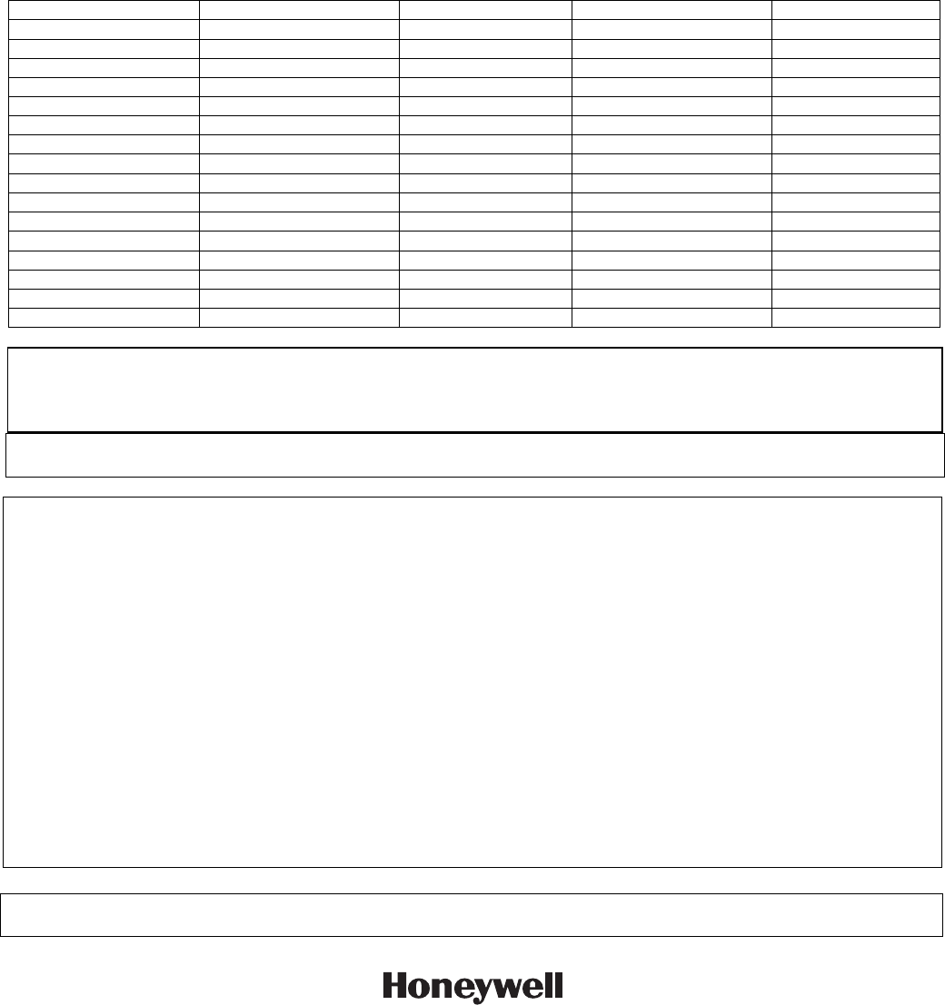
Multiple Button Operations
The 5805BDV should NOT be used for 24-hour
silent alarm, as the unit itself is not silent. Also, it is
recommended that the unit NOT be programmed for
a one-button panic.
The 5805BDV can generate the same responses as keypad panic
key pairs of [1] + [✱] and [✱] + [#] by depressing ON + 1 and
OFF + 2 button pairs, respectively.
You must depress the button pair for at least 2 seconds for the
5805BDV to recognize the button pair command. These button
pairs allow the user to activate panic, fire, and medical alarms
depending on control panel programming.
5805BDV-004-V0
OFF
2
ON
1
Specifications
Physical: Transmitter: 2.8” H x 1.8” W x 0.69” D
Battery: 1.5VDC, AAA, Alkaline
ÊK5756HŠ
K5756 2/05 Rev. A
NOTE: The following table contains the zone descriptors that can be annunciated by the 5805BDV. The control panel and
transceiver must be capable of transmitting these same descriptors to the 5805BDV. Refer to the panel’s Installation and
Setup Guide for zone descriptor words that match the words in the following table. The 5805BDV cannot annunciate
Custom Words or any words that are not contained in this table.
ALARM ENTER MAIN SECOND ZONE
ATTIC EXIT MASTER SET
AWAY FAULT MAX SHED ONE
BABY FIRE MEDICAL SHOP TWO
BACK FIRST MESSAGE SIDE THREE
BASEMENT FLOOR MINUTES STAY FOUR
BATHROOM FRONT MOTION SLIDING FIVE
BEDROOM GARAGE NOW SMOKE SIX
BYPASSED GUN NOT STORAGE SEVEN
CHECK HALL OFFICE SYSTEM EIGHT
CHIMED HOUR ON THIRD NINE
CLOSED INSIDE OPEN TO TEN
DEN INSTANT PANIC UPSTAIRS
DETECTOR KITCHEN PATIO UTILITY TWENTY
DINING LAUNDRY POOL WINDOW
DOOR LIBRARY READY YARD THIRTY
EMERGENCY LIVING ROOM ZERO
FCC ID: CFS8DL5805BDV-1
This device complies with Part 15 of the FCC rules. Operation is subject to the following two conditions: (1) This device may
not cause harmful interference, and (2) This device must accept any interference received, including interference that may
cause undesired operation.
Industry Canada:
CANADA 573F-5805BDV1
FEDERAL COMMUNICATIONS COMMISSION (FCC) Part 15 STATEMENT
This equipment has been tested to FCC requirements and has been found acceptable for use. The FCC requires the following statement for
your information:
This equipment generates and uses radio frequency energy and if not installed and used properly, that is, in strict accordance with the manu-
facturer's instructions, may cause interference to radio and television reception. It has been type tested and found to comply with the limits
for a Class B computing device in accordance with the specifications in Part 15 of FCC Rules, which are designed to provide reasonable pro-
tection against such interference in a residential installation. However, there is no guarantee that interference will not occur in a particular in-
stallation. If this equipment does cause interference to radio or television reception, which can be determined by turning the equipment off
and on, the user is encouraged to try to correct the interference by one or more of the following measures:
• If using an indoor antenna, have a quality outdoor antenna installed.
• Reorient the receiving antenna until interference is reduced or eliminated.
• Move the radio or television receiver away from the receiver/control.
• Move the antenna leads away from any wire runs to the receiver/control.
• Plug the receiver/control into a different outlet so that it and the radio or television receiver are on different branch circuits.
If necessary, the user should consult the dealer or an experienced radio/television technician for additional suggestions. The user or installer
may find the following booklet prepared by the Federal Communications Commission helpful: "Interference Handbook."
This booklet is available from the U.S. Government Printing Office, Washington, DC 20402.
The user shall not make any changes or modifications to the equipment unless authorized by the Installation Instructions or User's Manual.
Unauthorized changes or modifications could void the user's authority to operate the equipment.
FOR WARRANTY INFORMATION AND LIMITATIONS OF THE ENTIRE ALARM SYSTEM, REFER TO THE INSTALLATION
INSTRUCTIONS FOR THE CONTROL WITH WHICH THIS DEVICE IS USED.
165 Eileen Way, Syosset, New York 11791
Copyright © 2004 Honeywell International, Inc.
www.honeywell.com/security