Ademco 8DL5806-2 smoke alarm transmitter User Manual N6353V5REVISED
Honeywell International Inc. smoke alarm transmitter N6353V5REVISED
UserManual.wiki
>
Ademco
>
8DL5806 2 User Manual
II with fcc statment
Navigation menu
Upload a User Manual
Namespaces
Wiki Guide
HTML
PDF
Info
Views
User Manual
Discussion / Help
Navigation
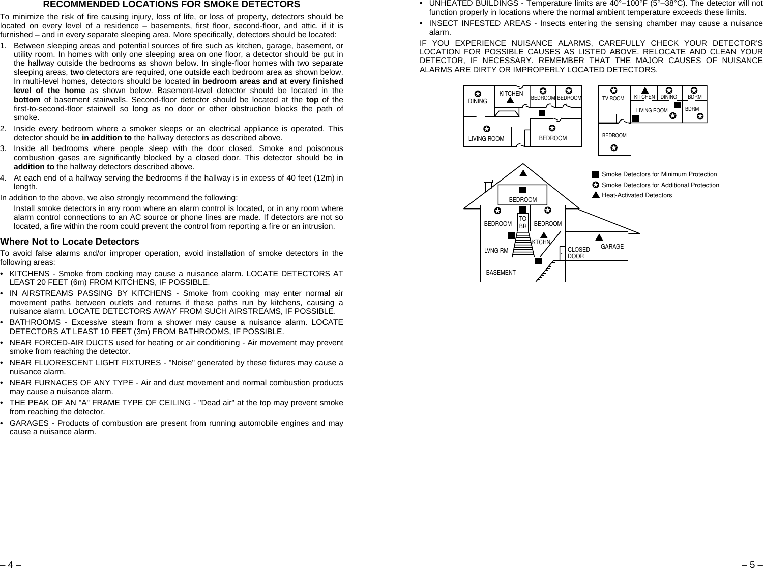
![– 2 – – 3 – 1. Remove the smoke detector from its mounting plate by twisting the detector counterclockwise. If you are replacing batteries, remove the existing batteries from their compartments and disconnect the battery clips. 2. Install the new 9-volt alkaline batteries in their respective compartments as follows: Snap the battery contacts onto the terminals of the first battery (be sure to observe correct polarity and do not force battery clips). Holding the contacts on the battery, install the battery into its compartment. Make sure the battery is fully seated (see Figure 1). Connect the second 9-volt alkaline battery in a similar manner and install it in the second compartment. 3. Re-install the smoke detector onto the mounting plate by turning it clockwise, and test its operation as described in the TEST section. 4. The LED indicator should flash about once every 40 seconds, indicating normal operation. If the batteries are not installed correctly, the smoke detector will not function. If the unit appears not to be sending a signal during any of the tests, check for correct battery installation. Note: If the detector’s ID has not been programmed into the system (i.e., this is an initial detector installation), refer to the PROGRAMMING section below and perform the ID “enrolling” procedure before mounting or testing the detector. Programming The control system must “enroll” the smoke detector’s ID during installation of the system. The control should be programmed to “enroll” the 5806 as an “RF” type unit (i.e., supervised RF), with a loop number of "1." With the control in the programming mode, you can either manually enter the serial number or transmit from the device (push the "Enroll" button [see Figure 1], install the battery, etc.). See the control unit’s installation instructions for further details. Be sure to verify that the detector has been enrolled into the system by using the procedure provided in TESTING THE SMOKE DETECTOR section on page 6. If a “low battery” message is displayed and you suspect that the batteries are not actually low, remove both batteries, wait 20 seconds, re-insert them, and re-test the detector. Repeat this procedure, if necessary. Tamper Protection For tamper protection, cut the wire jumper indicated in Figure 1. After the detector has been mounted, a magnet must then be installed on the wall or ceiling next to the detector. To ensure proper positioning of the magnet after the detector has been mounted, place a light pencil mark on the side of the detector near the center of the reed switch (see Fig. 1). “ENROLL” BUTTON(INSIDE OPENING). PUSH (WITH SMALLSCREWDRIVER) TOSEND “FAULT”.CUT JUMPER FOR TAMPERLOCATION OF “ENROLL” BUTTONAND “TAMPER” JUMPERREED SWITCH9 VOLTBATTERYCOMPARTMENTSINDEXINGMARKHOLDING TABS.LOCKING TABS ON MOUNTING PLATE SLIDE BENEATHTHESE TABS (DETECTOR IS LATCHED ONTO MOUNT-ING PLATE BY TURNING CLOCKWISE)*ONLY IF TAMPERMAGNET WILL BEUSEDMAGNETIC REEDSWITCHPLACE LIGHTPENCIL MARKHERE*INDEXINGMARK“ENROLL”BUTTON9V BATTERY9V BATTERYADEMCO Model No. 5806 Figure 1. Bottom View of Smoke Detector (without mounting plate) Mounting the Smoke Detector First, determine the best location for the smoke detector (one that provides strong wireless transmission paths AND proper smoke detector protection). See RECOMMENDED LOCATIONS FOR SMOKE DETECTORS (on next page). A good RF transmission path must be established from the proposed mounting location before permanently installing the detector. To check, perform the test in TESTING THE SMOKE DETECTOR. Mounting Locations Detectors should be located as close to the center of the ceiling as possible. If this is not practical, detectors may be located on the ceiling up to 4 inches (10cm) from the ceiling-wall junction. Do not install near forced-air heating or air conditioning ducts (outlets or returns). For sloped, gabled, or high-peaked ceilings, detectors must be mounted between 4 and 6 inches (10 and 15cm) from the highest point in the ceiling. Detectors may also be wall-mounted. Check with your local Fire Department about code requirements. Wall-mounted detectors should be located 4–6 inches (10–15 cm) from the ceiling. In mobile homes, battery-operated detectors are not generally installed by the manufacturer. Mount detectors ONLY on an interior wall. 1. Once a suitable location has been determined, install the mounting plate on the ceiling or on the wall. Use the two screws and anchors provided. 2. Latch the detector onto the mounting plate as follows: Position the detector onto the plate, mating the small center post on the detector with the "dimple" at the center of the mounting plate, and aligning the index marks on the sides of the plate and the detector. Then turn the detector in a clockwise direction so that the holding tabs on the detector engage the locking tabs on the mounting plate. 3. If the tamper has been enabled (as indicated previously), a magnet (No. 39WH-M) should be mounted on the wall or ceiling surface next to the detector (1/4” max) in the specified location (see Fig. 2). 4. Test the detector immediately after completing the installation and refer to the control system's instructions for additional information concerning the use of wireless smoke detectors. DEAD AIRSPACE4 IN.(10 cm)CEILINGBEST INCORNER ACCEPTABLEHEREACCEPTABLEHERENOTE:MEASUREMENTSSHOWN ARE TO THECLOSEST EDGE OFTHE DETECTOR. SIDE WALLNEVERHERE4 IN.6 IN.(10 cm)(15 cm) SLOTTED HOLESFOR MOUNTINGSCREWSINDEXING MARK LOCKING TABS(USED FOR SECURINGSMOKE DETECTORTO MOUNTING PLATE)INDEXING MARKNOTE:OTHER SIDE FACES CEILING OR WALL(THE WORDS “SINGLE GANG” MUST FACEAWAY FROM MOUNTING SURFACE)ACE). TEST BUTTONINSTALLATION OF MAGNET (FOR TAMPER PROTECTION)INDEXING MARK1/4" MAXNo.39WH-M MAGNETNOTE: MAGNET IS MOUNTED NEXT TODETECTOR ON SIDEOPPOSITE TESTBUTTON.Figure 2. Mounting Details](https://usermanual.wiki/Ademco/8DL5806-2/User-Guide-585436-Page-2.png)