Ademco 8DL5806-2 smoke alarm transmitter User Manual N6353V5REVISED
Honeywell International Inc. smoke alarm transmitter N6353V5REVISED
Ademco >
II with fcc statment
LIMITED WARRANTY
Honeywell International Inc., acting through its Security & Custom Electronics business ("Seller") 165
Eileen Way, Syosset, New York 11791, warrants its product(s) to be in conformance with its own plans
and specifications and to be free from defects in materials and workmanship under normal use and
service for 24 months from the date stamp control on the product(s) or, for product(s) not having a
manufacturer’s date stamp, for 12 months from date of original purchase unless the installation
instructions or catalog sets forth a shorter period, in which case the shorter period shall apply. Seller's
obligation shall be limited to repairing or replacing, at its option, free of charge for materials or labor, any
product(s) which is proved not in compliance with Seller's specifications or proves defective in materials
or workmanship under normal use and service. Seller shall have no obligation under this Limited
Warranty or otherwise if the product(s) is altered or improperly repaired or serviced by anyone other
than Honeywell factory service. For warranty service, return product(s) transportation prepaid, to
Honeywell Factory Service, 165 Eileen Way, Syosset, New York 11791.
THERE ARE NO WARRANTIES, EXPRESS OR IMPLIED, OF MERCHANTABILITY, OR FITNESS
FOR A PARTICULAR PURPOSE OR OTHERWISE, WHICH EXTEND BEYOND THE DESCRIPTION
ON THE FACE HEREOF. IN NO CASE SHALL SELLER BE LIABLE TO ANYONE FOR ANY
CONSEQUENTIAL OR INCIDENTAL DAMAGES FOR BREACH OF THIS OR ANY OTHER
WARRANTY, EXPRESS OR IMPLIED, OR UPON ANY OTHER BASIS OF LIABILITY WHATSOEVER,
EVEN IF THE LOSS OR DAMAGE IS CAUSED BY THE SELLER'S OWN NEGLIGENCE OR FAULT.
Seller does not represent that the product(s) it sells may not be compromised or circumvented; that the
product(s) will prevent any personal injury or property loss by burglary, robbery, fire or otherwise; or that
the product(s) will in all cases provide adequate warning or protection. Customer understands that a
properly installed and maintained alarm system may only reduce the risk of a burglary, robbery, fire, or
other events occurring without providing an alarm, but it is not insurance or a guarantee that such will
not occur or that there will be no personal injury or property loss as a result. CONSEQUENTLY,
SELLER SHALL HAVE NO LIABILITY FOR ANY PERSONAL INJURY, PROPERTY DAMAGE OR
OTHER LOSS BASED ON A CLAIM THAT THE PRODUCT(S) FAILED TO GIVE WARNING.
HOWEVER, IF SELLER IS HELD LIABLE, WHETHER DIRECTLY OR INDIRECTLY, FOR ANY LOSS
OR DAMAGE ARISING UNDER THIS LIMITED WARRANTY OR OTHERWISE, REGARDLESS OF
CAUSE OR ORIGIN, SELLER'S MAXIMUM LIABILITY SHALL NOT IN ANY CASE EXCEED THE
PURCHASE PRICE OF THE PRODUCT(S), WHICH SHALL BE THE COMPLETE AND EXCLUSIVE
REMEDY AGAINST SELLER.
This warranty replaces any previous warranties and is the only warranty made by Seller on this
product(s). No increase or alteration, written or verbal, of the obligations of this Limited Warranty is
authorized.
FCC STATEMENT
FCC ID: CFS8DL5806-2
This device complies with Part 15 of the FCC Rules. Operation is subject
to the following two conditions: (1) This device may not cause harmful
interference (2) This device must accept any interference received,
including interference that may cause undesired operation.
IC: 573F-58062
165 Eileen Way, Syosset, New York 11791
Copyright © 2004 Honeywell International Inc.
www.honeywell.com/security
ÊN6353V5mŠ
N6353V5 7/04 Rev A
N6353V5 7/04 Rev A
ADEMCO 5806
Smoke Detector With Built-In
Wireless Transmitter
INSTALLATION INSTRUCTIONS
General Information
The ADEMCO 5806 Photoelectric Smoke
Detector/Transmitter is intended for use with
wireless alarm systems that support 5800
Series devices, and contains a built-in
transmitter that can send alarm, supervisory
and battery condition messages to the
system's receiver/control unit. Refer to the
wireless system's instructions for the
maximum number of transmitters that can be
supported.
Alarms: The smoke detector is powered by
two 9-volt batteries and will sound its built-in
horn when smoke reaches the detector (the
LED indicator will also flash rapidly). A
message will also be sent to the wireless
control and the smoke detector's ID number
will be displayed at the keypad. The alarm
message will be transmitted every 4 seconds,
until the smoke condition has cleared and the
detector has reset. About 1 second after the
horn has stopped, a Restore message will be
transmitted to the control and it will then be
possible to clear the ID number from the
display. During normal or low battery
conditions, the LED indicator will flash about
once every 40 seconds.
Low Battery: The detector indicates a low-
battery condition by emitting a "chirp" about
once every 40 seconds. A low-battery
message will be sent to the control unit upon
any transmission following the first battery
chirp (with the detector's ID number displayed
at the keypad). The battery should be replaced
within 30 days following the low-battery
signals.
False Alarm Protection: In order to reduce
the possibility of false alarms due to cigarette
smoke, dust, steam, insects, etc., the detector
will not transmit an alarm signal until its horn
has sounded continuously for about 6
seconds. A delay also occurs when the
detector is tested. Therefore, the test button
must be held down for about 20 seconds
before the horn will sound. The first alarm
signal will be transmitted within 6 seconds after
the horn sounds.
Programming: Note that the control system
must “enroll” the smoke detector’s ID during
installation of the system. The control should
be programmed to “enroll” the 5806 as an “RF”
type unit (i.e., supervised RF). See the
PROGRAMMING section in this instruction
book and the control unit’s Installation
Instructions for further details.
Tamper Protection: The detector has
provision for a tamper function if desired.
When the tamper function, is enabled, the
detector will cause a CHECK to be displayed if
it is removed from its installed location. See
TAMPER PROTECTION for detailed
instructions.
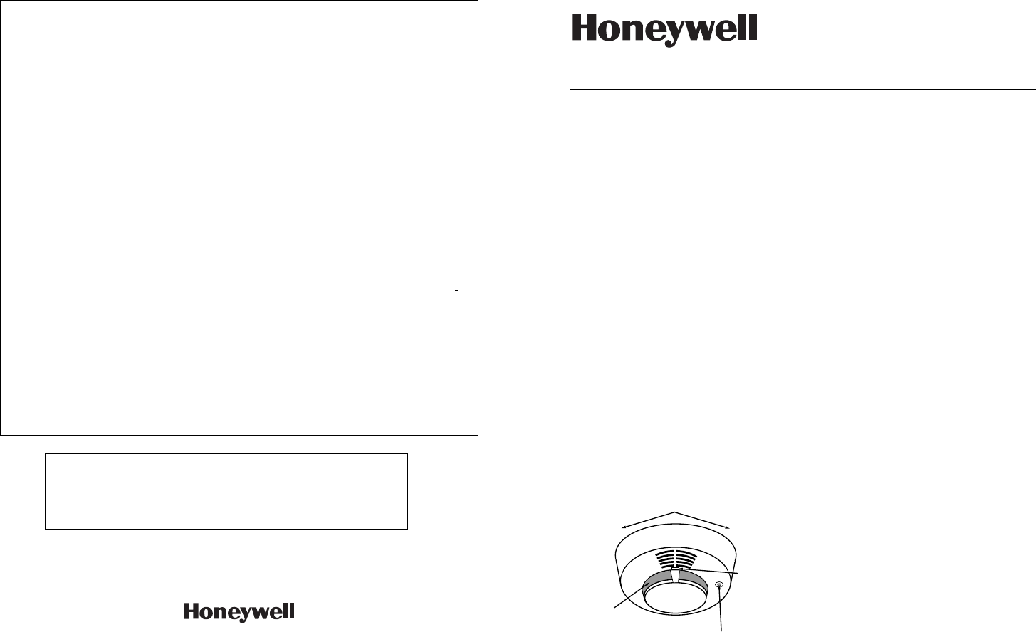
Battery Installation and
Replacement
TO REMOVE TO SECURE
INDICATOR LIGHT.
FLASHES ONCE
EVERY 40 SECS
DURING NORMAL
OPERATION
TEST BUTTON
SENSING
CHAMBER
OPENINGS
The 5806 is equipped with two 9-volt batteries,
which can double the time between battery
replacement (compared to a single 9-volt
alkaline battery). Refer to the
SPECIFICATIONS section for acceptable
batteries. The batteries should be changed
within 30 days following the low battery beeps
(about once every 40 seconds). There will
also be a low-battery display on the system’s
keypad. Be sure to replace BOTH batteries
with fresh ones.
Important: Do not mix battery types.
– 2 – – 3 –
1. Remove the smoke detector from its
mounting plate by twisting the detector
counterclockwise. If you are replacing
batteries, remove the existing batteries from
their compartments and disconnect the
battery clips.
2. Install the new 9-volt alkaline batteries in
their respective compartments as follows:
Snap the battery contacts onto the terminals
of the first battery (be sure to observe
correct polarity and do not force battery
clips). Holding the contacts on the battery,
install the battery into its compartment.
Make sure the battery is fully seated (see
Figure 1).
Connect the second 9-volt alkaline
battery in a similar manner and install it in
the second compartment.
3. Re-install the smoke detector onto the
mounting plate by turning it clockwise,
and test its operation as described in the
TEST section.
4. The LED indicator should flash about
once every 40 seconds, indicating normal
operation. If the batteries are not installed
correctly, the smoke detector will not
function. If the unit appears not to be
sending a signal during any of the tests,
check for correct battery installation.
Note: If the detector’s ID has not been programmed into the system (i.e., this is an initial
detector installation), refer to the PROGRAMMING section below and perform the ID
“enrolling” procedure before mounting or testing the detector.
Programming
The control system must “enroll” the smoke detector’s ID during installation of the system. The
control should be programmed to “enroll” the 5806 as an “RF” type unit (i.e., supervised RF), with
a loop number of "1." With the control in the programming mode, you can either manually enter
the serial number or transmit from the device (push the "Enroll" button [see Figure 1], install the
battery, etc.). See the control unit’s installation instructions for further details.
Be sure to verify that the detector has been enrolled into the system by using the procedure
provided in TESTING THE SMOKE DETECTOR section on page 6.
If a “low battery” message is displayed and you suspect that the batteries are not actually low,
remove both batteries, wait 20 seconds, re-insert them, and re-test the detector. Repeat this
procedure, if necessary.
Tamper Protection
For tamper protection, cut the wire jumper indicated in Figure 1. After the detector has been
mounted, a magnet must then be installed on the wall or ceiling next to the detector.
To ensure proper positioning of the magnet after the detector has been mounted, place a light
pencil mark on the side of the detector near the center of the reed switch (see Fig. 1).
“ENROLL” BUTTON
(INSIDE OPENING).
PUSH (WITH SMALL
SCREWDRIVER) TO
SEND “FAULT”.
CUT JUMPER
FOR TAMPER
LOCATION OF “ENROLL” BUTTON
AND “TAMPER” JUMPER
REED SWITCH
9 VOLT
BATTERY
COMPARTMENTS
INDEXING
MARK
HOLDING TABS.
LOCKING TABS ON MOUNTING PLATE SLIDE BENEATH
THESE TABS (DETECTOR IS LATCHED ONTO MOUNT-
ING PLATE BY TURNING CLOCKWISE)
*
ONLY IF TAMPER
MAGNET WILL BE
USED
MAGNETIC REED
SWITCH
PLACE LIGHT
PENCIL MARK
HERE*
INDEXING
MARK
“ENROLL”
BUTTON
9V
BATTERY
9V
BATTERY
ADEMCO
Model No. 5806
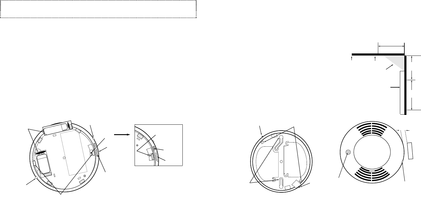
Figure 1. Bottom View of Smoke Detector (without mounting plate)
Mounting the Smoke Detector
First, determine the best location for the
smoke detector (one that provides strong
wireless transmission paths AND proper
smoke detector protection). See
RECOMMENDED LOCATIONS FOR
SMOKE DETECTORS (on next page).
A good RF transmission path must be
established from the proposed mounting
location before permanently installing the
detector. To check, perform the test in
TESTING THE SMOKE DETECTOR.
Mounting Locations
Detectors should be located as close to the
center of the ceiling as possible. If this is not
practical, detectors may be located on the
ceiling up to 4 inches (10cm) from the
ceiling-wall junction. Do not install near
forced-air heating or air conditioning ducts
(outlets or returns). For sloped, gabled, or
high-peaked ceilings, detectors must be
mounted between 4 and 6 inches (10 and
15cm) from the highest point in the ceiling.
Detectors may also be wall-mounted. Check
with your local Fire Department about code
requirements. Wall-mounted detectors
should be located 4–6 inches (10–15 cm)
from the ceiling.
In mobile homes, battery-operated detectors
are not generally installed by the
manufacturer. Mount detectors ONLY on an
interior wall.
1. Once a suitable location has been
determined, install the mounting plate
on the ceiling or on the wall. Use the
two screws and anchors provided.
2. Latch the detector onto the mounting
plate as follows: Position the detector
onto the plate, mating the small center
post on the detector with the "dimple" at
the center of the mounting plate, and
aligning the index marks on the sides of
the plate and the detector. Then turn the
detector in a clockwise direction so that
the holding tabs on the detector engage
the locking tabs on the mounting plate.
3. If the tamper has been enabled (as
indicated previously), a magnet (No.
39WH-M) should be mounted on the wall
or ceiling surface next to the detector
(1/4” max) in the specified location (see
Fig. 2).
4. Test the detector immediately after
completing the installation and refer to
the control system's instructions for
additional information concerning the use
of wireless smoke detectors.
DEAD AIR
SPACE
4 IN.
(10 cm)
CEILING
BEST IN
CORNER ACCEPTABLE
HERE
ACCEPTABLE
HERE
NOTE:
MEASUREMENTS
SHOWN ARE TO THE
CLOSEST EDGE OF
THE DETECTOR. SIDE WALL
NEVER
HERE
4 IN.
6 IN.
(10 cm)
(15 cm)
SLOTTED HOLES
FOR MOUNTING
SCREWS
INDEXING MARK LOCKING TABS
(USED FOR SECURING
SMOKE DETECTOR
TO MOUNTING PLATE)
INDEXING MARK
NOTE:
OTHER SIDE FACES CEILING OR WALL
(THE WORDS “SINGLE GANG” MUST FACE
AWAY FROM MOUNTING SURFACE)
ACE).
TEST BUTTON
INSTALLATION OF MAGNET (FOR TAMPER PROTECTION)
INDEXING MARK
1/4" MAX
No.39WH-M MAGNET
NOTE: MAGNET IS
MOUNTED NEXT TO
DETECTOR ON SIDE
OPPOSITE TEST
BUTTON.
Figure 2. Mounting Details
– 4 – – 5 –
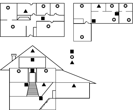
RECOMMENDED LOCATIONS FOR SMOKE DETECTORS
To minimize the risk of fire causing injury, loss of life, or loss of property, detectors should be
located on every level of a residence – basements, first floor, second-floor, and attic, if it is
furnished – and in every separate sleeping area. More specifically, detectors should be located:
1. Between sleeping areas and potential sources of fire such as kitchen, garage, basement, or
utility room. In homes with only one sleeping area on one floor, a detector should be put in
the hallway outside the bedrooms as shown below. In single-floor homes with two separate
sleeping areas, two detectors are required, one outside each bedroom area as shown below.
In multi-level homes, detectors should be located in bedroom areas and at every finished
level of the home as shown below. Basement-level detector should be located in the
bottom of basement stairwells. Second-floor detector should be located at the top of the
first-to-second-floor stairwell so long as no door or other obstruction blocks the path of
smoke.
2. Inside every bedroom where a smoker sleeps or an electrical appliance is operated. This
detector should be in addition to the hallway detectors as described above.
3. Inside all bedrooms where people sleep with the door closed. Smoke and poisonous
combustion gases are significantly blocked by a closed door. This detector should be in
addition to the hallway detectors described above.
4. At each end of a hallway serving the bedrooms if the hallway is in excess of 40 feet (12m) in
length.
In addition to the above, we also strongly recommend the following:
Install smoke detectors in any room where an alarm control is located, or in any room where
alarm control connections to an AC source or phone lines are made. If detectors are not so
located, a fire within the room could prevent the control from reporting a fire or an intrusion.
Where Not to Locate Detectors
To avoid false alarms and/or improper operation, avoid installation of smoke detectors in the
following areas:
• KITCHENS - Smoke from cooking may cause a nuisance alarm. LOCATE DETECTORS AT
LEAST 20 FEET (6m) FROM KITCHENS, IF POSSIBLE.
• IN AIRSTREAMS PASSING BY KITCHENS - Smoke from cooking may enter normal air
movement paths between outlets and returns if these paths run by kitchens, causing a
nuisance alarm. LOCATE DETECTORS AWAY FROM SUCH AIRSTREAMS, IF POSSIBLE.
• BATHROOMS - Excessive steam from a shower may cause a nuisance alarm. LOCATE
DETECTORS AT LEAST 10 FEET (3m) FROM BATHROOMS, IF POSSIBLE.
• NEAR FORCED-AIR DUCTS used for heating or air conditioning - Air movement may prevent
smoke from reaching the detector.
• NEAR FLUORESCENT LIGHT FIXTURES - "Noise" generated by these fixtures may cause a
nuisance alarm.
• NEAR FURNACES OF ANY TYPE - Air and dust movement and normal combustion products
may cause a nuisance alarm.
• THE PEAK OF AN "A" FRAME TYPE OF CEILING - "Dead air" at the top may prevent smoke
from reaching the detector.
• GARAGES - Products of combustion are present from running automobile engines and may
cause a nuisance alarm.
• UNHEATED BUILDINGS - Temperature limits are 40°–100°F (5°–38°C). The detector will not
function properly in locations where the normal ambient temperature exceeds these limits.
• INSECT INFESTED AREAS - Insects entering the sensing chamber may cause a nuisance
alarm.
IF YOU EXPERIENCE NUISANCE ALARMS, CAREFULLY CHECK YOUR DETECTOR'S
LOCATION FOR POSSIBLE CAUSES AS LISTED ABOVE. RELOCATE AND CLEAN YOUR
DETECTOR, IF NECESSARY. REMEMBER THAT THE MAJOR CAUSES OF NUISANCE
ALARMS ARE DIRTY OR IMPROPERLY LOCATED DETECTORS.
DINING KITCHEN
BEDROOM
BEDROOM
BEDROOM
BEDROOM
LIVING ROOM
BEDROOM
BDRM
BDRM
DINING
LIVING ROOM
TV ROOM KITCHEN
BEDROOM BEDROOM
TO
BR
LVNG RM
BASEMENT
KTCHN
.
CLOSED
DOOR
GARAGE
Smoke Detectors for Minimum Protection
Smoke Detectors for Additional Protection
Heat-Activated Detectors

– 6 – – 7 –
Testing The Smoke Detector
The following procedure should be performed to determine strong radio path communication with
the control, and again after installation is completed. THIS TEST SHOULD ALSO BE
PERFORMED ON A REGULAR BASIS (AT LEAST WEEKLY) BY THE USER.
1. Activate the wireless system's TEST
mode via the keypad.
2. Depress and hold the smoke detector's
TEST button. Within 20 seconds, the
detector's horn will start to sound. The
detector will begin to transmit alarm
signals (about once every 4 seconds)
within 6 seconds of the horn sounding.
3. The wireless system's keypad should
emit at least 3 audible sounds when the
alarm transmission is received, and will
display the transmitting detector's ID
number.
4. When satisfied that the keypad has
received the test signal, release the TEST
button. Within 10 seconds the
detector's horn will stop. A few seconds
later, the smoke detector’s ID number will
be cleared from the keypad display.
5. If the keypad does not respond as noted,
check battery connections and be sure
batteries are fresh. If this is an initial
installation, try moving the detector to
another location that provides proper
reception. Repeat test.
NOTE: Be sure that the detector’s ID has
been “enrolled” by the control during
programming (see information on
Programming on pages 1 and 2).
6. Turn off the system's TEST mode via the
keypad (security code + OFF).
Testing the Tamper Function (if used) after Mounting the Detector
With the system in the normal disarmed mode, temporarily detach the smoke detector from
its mounting plate. The system’s keypad should display a CHECK message. If it does not,
check that the magnet has been installed in the correct location next to the detector. Also,
check that the wire tamper jumper in the detector has been cut.
SUMMARY OF DETECTOR FUNCTIONS
POWER/ALARM LED HORN STATUS
Pulses every 40
seconds Silent Normal, functioning properly
Pulses every 40
seconds Beeps once every 40
seconds Low battery or detector malfunction
Rapid flashing On continuously Alarm, detecting smoke
Specifications
Power Source: Two 9-volt alkaline batteries. Use ADEMCO 464,
Eveready 522, Duracell MN1604, or equivalent.
Power/Alarm LED: Standby = flashing once every 40 seconds.
Alarm = rapid flashing.
Low-Battery Signal: One horn “chirp” every 40 seconds.
Size: 5-5/8" inch (14cm) diameter, 2-1/2" inch (6.4cm) high.
TO THE INSTALLER
Regular maintenance and inspection (at least annually) by the installer and frequent testing
by the user are vital to continuous satisfactory operation of any alarm system.
The installer should assume the responsibility of developing and offering a regular
maintenance program to the user as well as acquainting the user with the proper operation
and limitations of the alarm system and its component parts. Recommendations must be
included for a specific program of frequent testing (at least weekly) to insure the system's
proper operation at all times.
THE LIMITATIONS OF THIS
SMOKE DETECTOR / TRANSMITTER
While this smoke detector/transmitter is a highly reliable device that is part of an advanced
wireless security system, it does not offer guaranteed protection against fire. While smoke
detectors have played a key role in reducing residential fire deaths, they may not activate or
provide early warning for a variety of reasons in as many as 35% of all fires. Some of the
reasons smoke detectors used in alarm systems may not work are as follows:
• Smoke detectors will not work without power. Battery-operated devices will not work
without batteries, or if the batteries are not put in properly.
• Smoke detectors may have been improperly installed and positioned. Smoke detectors may
not sense fires that start where smoke cannot reach the detectors, such as in chimneys, in
walls, on the roof, or on the other side of closed doors. Smoke detectors also may not
sense a fire on another level of a residence or building. A second-floor detector, for
example, may not sense a first-floor fire or basement fire. In addition, smoke detectors
have sensing limitations. No smoke detector can sense every kind of fire every time. In
general, detectors may not always provide adequate warning about rapidly spreading fires
caused by carelessness and safety hazards like smoking in bed, violent explosions,
escaping gas, improper storage of flammable materials, children playing with matches, or
arson. Depending on the nature of the fire and/or location of the smoke detectors, the
detector, even if it operates as anticipated, may not provide sufficient warning to allow all
occupants to escape in time to prevent injury or death.
• Alarm signals sent by the wireless transmitter in this device may be blocked or reflected by
metal before they reach the alarm receiver. Even if the signal path has been recently
checked during a weekly test, blockage can occur if a metal object is moved into the path.
• Alarm warning devices such as sirens, bells, or horns may not alert people or wake up
sleepers if they are located on the other side of closed or partly open doors. If warning
devices are located on a different level of the residence from the bedrooms, then they are
less likely to waken or alert people inside the bedrooms. Even persons who are awake
may not hear the warning if the alarm is muffled by noise from a stereo, radio, air
conditioner, or other appliances, or by passing traffic. Finally, alarm warning devices,
however loud, may not warn hearing-impaired people or waken deep sleepers.
• This smoke detector/transmitter, like other electrical devices, is subject to component
failure. Even though this device is designed to last as long as 20 years, the electronic
components in it could fail at any time. We recommend that smoke detectors be replaced
every 10 years as a precautionary measure against component failure.
The most common cause of an alarm system not functioning when a fire occurs is inadequate
maintenance. The alarm system should be tested weekly to make sure all smoke detectors
and their transmitters are working properly. Detectors must be repaired or replaced when they
do not function properly.
Installing an alarm system may make the owner eligible for lower insurance rates, but an
alarm system is not a substitute for insurance. Homeowners, property owners, and renters
should continue to act prudently in protecting themselves and continue to insure their lives
and property.
We continue to develop new and improved protection devices. Users of alarm systems owe it
to themselves and their loved ones to learn about these developments.