Ademco 8DL5809XT Wireless Rate-of-Rise Heat Detector User Manual 5809 Wireless Rate of Rise Heat Detector
Honeywell International Inc. Wireless Rate-of-Rise Heat Detector 5809 Wireless Rate of Rise Heat Detector
Ademco >
Contents
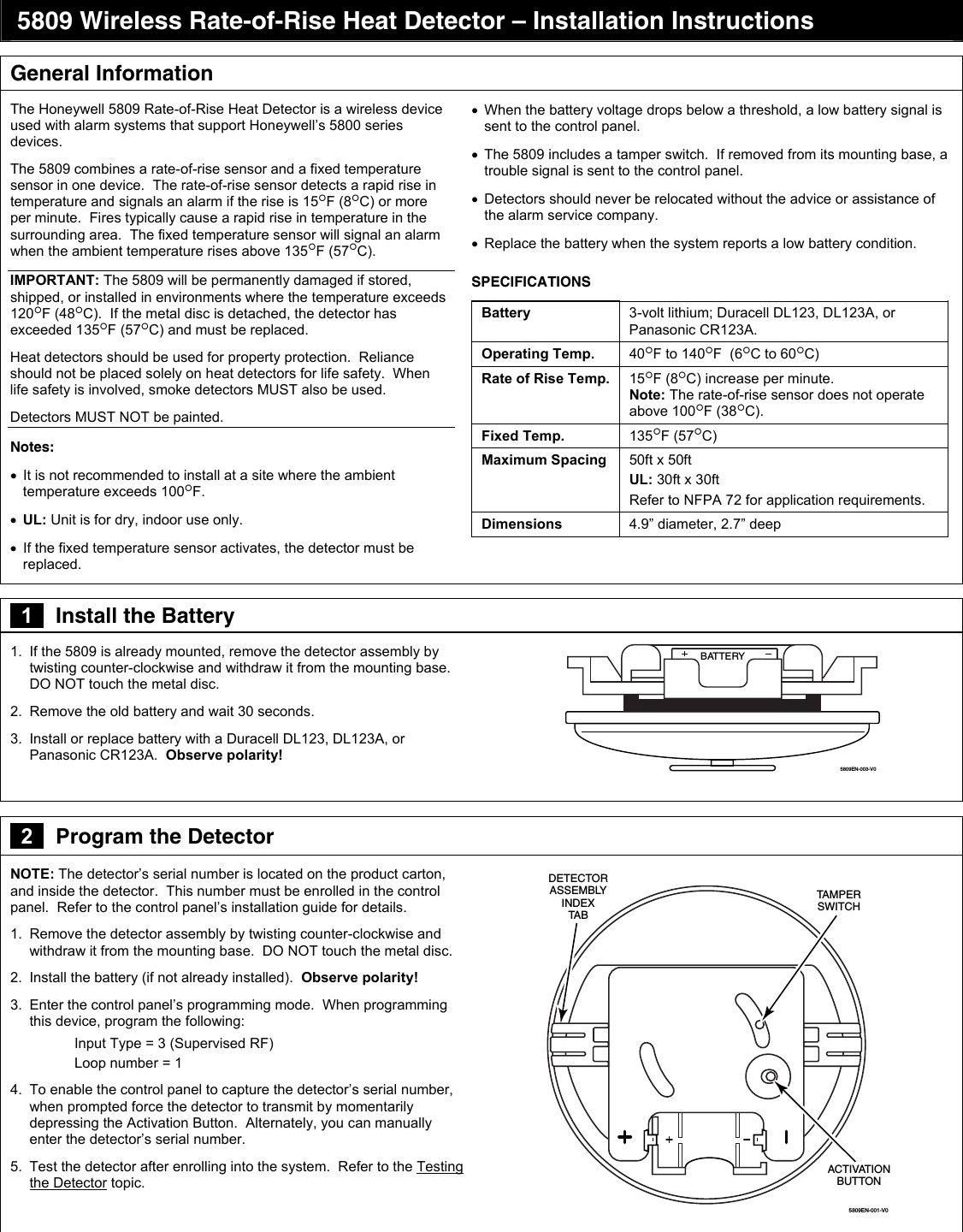
- 1. Users Manual 1
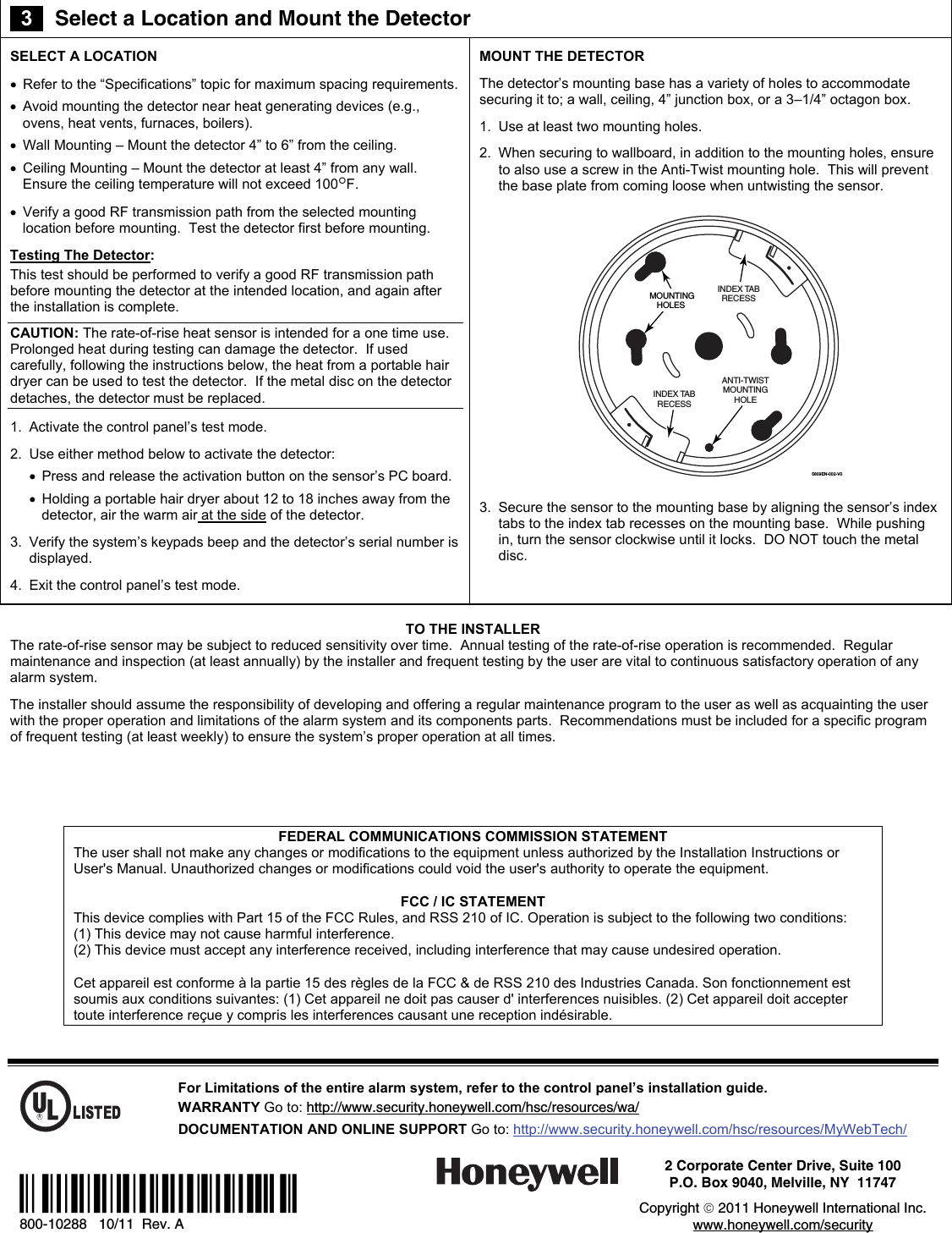
- 2. Users Manual 2
Users Manual 1