Ademco 8DL5809XT Wireless Rate-of-Rise Heat Detector User Manual 5809 Wireless Rate of Rise Heat Detector
Honeywell International Inc. Wireless Rate-of-Rise Heat Detector 5809 Wireless Rate of Rise Heat Detector
Ademco >
Contents
- 1. Users Manual 1
- 2. Users Manual 2
Users Manual 1
5809 Wireless Rate-of-Rise Heat Detector – Installation Instructions
General Information
The Honeywell 5809 Rate-of-Rise Heat Detector is a wireless device
used with alarm systems that support Honeywell’s 5800 series
devices.
The 5809 combines a rate-of-rise sensor and a fixed temperature
sensor in one device. The rate-of-rise sensor detects a rapid rise in
temperature and signals an alarm if the rise is 15F (8C) or more
per minute. Fires typically cause a rapid rise in temperature in the
surrounding area. The fixed temperature sensor will signal an alarm
when the ambient temperature rises above 135F (57C).
IMPORTANT: The 5809 will be permanently damaged if stored,
shipped, or installed in environments where the temperature exceeds
120F (48C). If the metal disc is detached, the detector has
exceeded 135F (57C) and must be replaced.
Heat detectors should be used for property protection. Reliance
should not be placed solely on heat detectors for life safety. When
life safety is involved, smoke detectors MUST also be used.
Detectors MUST NOT be painted.
Notes:
It is not recommended to install at a site where the ambient
temperature exceeds 100F.
UL: Unit is for dry, indoor use only.
If the fixed temperature sensor activates, the detector must be
replaced.
When the battery voltage drops below a threshold, a low battery signal is
sent to the control panel.
The 5809 includes a tamper switch. If removed from its mounting base, a
trouble signal is sent to the control panel.
Detectors should never be relocated without the advice or assistance of
the alarm service company.
Replace the battery when the system reports a low battery condition.
SPECIFICATIONS
Battery 3-volt lithium; Duracell DL123, DL123A, or
Panasonic CR123A.
Operating Temp. 40F to 140F (6C to 60C)
Rate of Rise Temp. 15F (8C) increase per minute.
Note: The rate-of-rise sensor does not operate
above 100F (38C).
Fixed Temp. 135F (57C)
Maximum Spacing 50ft x 50ft
UL: 30ft x 30ft
Refer to NFPA 72 for application requirements.
Dimensions 4.9” diameter, 2.7” deep
zzz
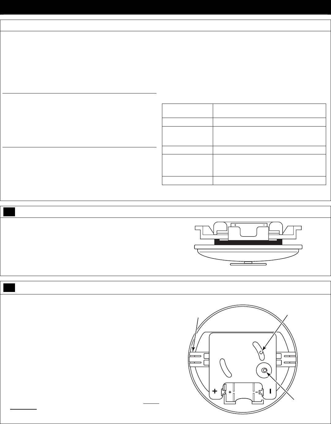
1 Install the Battery
1. If the 5809 is already mounted, remove the detector assembly by
twisting counter-clockwise and withdraw it from the mounting base.
DO NOT touch the metal disc.
2. Remove the old battery and wait 30 seconds.
3. Install or replace battery with a Duracell DL123, DL123A, or
Panasonic CR123A. Observe polarity!
BATTERY
5809EN-003-V0
2 Program the Detector
NOTE: The detector’s serial number is located on the product carton,
and inside the detector. This number must be enrolled in the control
panel. Refer to the control panel’s installation guide for details.
1. Remove the detector assembly by twisting counter-clockwise and
withdraw it from the mounting base. DO NOT touch the metal disc.
2. Install the battery (if not already installed). Observe polarity!
3. Enter the control panel’s programming mode. When programming
this device, program the following:
Input Type = 3 (Supervised RF)
Loop number = 1
4. To enable the control panel to capture the detector’s serial number,
when prompted force the detector to transmit by momentarily
depressing the Activation Button. Alternately, you can manually
enter the detector’s serial number.
5. Test the detector after enrolling into the system. Refer to the Testing
the Detector topic.
5809EN-001-V0
ACTIVATION
BUTTON
DETECTOR
ASSEMBLY
INDEX
TA B
TAMPER
SWITCH
3 Select a Location and Mount the Detector
SELECT A LOCATION
Refer to the “Specifications” topic for maximum spacing requirements.
Avoid mounting the detector near heat generating devices (e.g.,
ovens, heat vents, furnaces, boilers).
Wall Mounting – Mount the detector 4” to 6” from the ceiling.
Ceiling Mounting – Mount the detector at least 4” from any wall.
Ensure the ceiling temperature will not exceed 100F.
Verify a good RF transmission path from the selected mounting
location before mounting. Test the detector first before mounting.
Testing The Detector:
This test should be performed to verify a good RF transmission path
before mounting the detector at the intended location, and again after
the installation is complete.
CAUTION: The rate-of-rise heat sensor is intended for a one time use.
Prolonged heat during testing can damage the detector. If used
carefully, following the instructions below, the heat from a portable hair
dryer can be used to test the detector. If the metal disc on the detector
detaches, the detector must be replaced.
1. Activate the control panel’s test mode.
2. Use either method below to activate the detector:
Press and release the activation button on the sensor’s PC board.
Holding a portable hair dryer about 12 to 18 inches away from the
detector, air the warm air at the side of the detector.
3. Verify the system’s keypads beep and the detector’s serial number is
displayed.
4. Exit the control panel’s test mode.
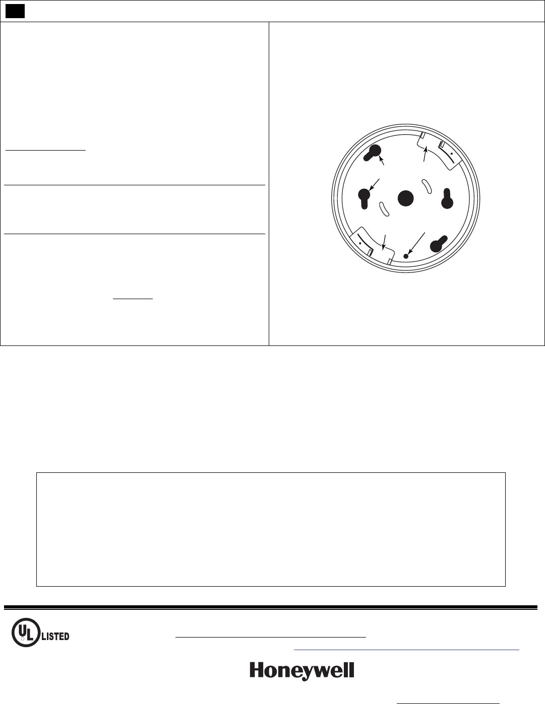
MOUNT THE DETECTOR
The detector’s mounting base has a variety of holes to accommodate
securing it to; a wall, ceiling, 4” junction box, or a 3–1/4” octagon box.
1. Use at least two mounting holes.
2. When securing to wallboard, in addition to the mounting holes, ensure
to also use a screw in the Anti-Twist mounting hole. This will prevent
the base plate from coming loose when untwisting the sensor.
5809EN-002-V0
INDEX TAB
RECESS
INDEX TAB
RECESS
ANTI-TWIST
MOUNTING
HOLE
MOUNTING
HOLES
3. Secure the sensor to the mounting base by aligning the sensor’s index
tabs to the index tab recesses on the mounting base. While pushing
in, turn the sensor clockwise until it locks. DO NOT touch the metal
disc.
TO THE INSTALLER
The rate-of-rise sensor may be subject to reduced sensitivity over time. Annual testing of the rate-of-rise operation is recommended. Regular
maintenance and inspection (at least annually) by the installer and frequent testing by the user are vital to continuous satisfactory operation of any
alarm system.
The installer should assume the responsibility of developing and offering a regular maintenance program to the user as well as acquainting the user
with the proper operation and limitations of the alarm system and its components parts. Recommendations must be included for a specific program
of frequent testing (at least weekly) to ensure the system’s proper operation at all times.
FEDERAL COMMUNICATIONS COMMISSION STATEMENT
The user shall not make any changes or modifications to the equipment unless authorized by the Installation Instructions or
User's Manual. Unauthorized changes or modifications could void the user's authority to operate the equipment.
FCC / IC STATEMENT
This device complies with Part 15 of the FCC Rules, and RSS 210 of IC. Operation is subject to the following two conditions:
(1) This device may not cause harmful interference.
(2) This device must accept any interference received, including interference that may cause undesired operation.
Cet appareil est conforme à la partie 15 des règles de la FCC & de RSS 210 des Industries Canada. Son fonctionnement est
soumis aux conditions suivantes: (1) Cet appareil ne doit pas causer d' interferences nuisibles. (2) Cet appareil doit accepter
toute interference reçue y compris les interferences causant une reception indésirable.
R
For Limitations of the entire alarm system, refer to the control panel’s installation guide.
WARRANTY Go to: http://www.security.honeywell.com/hsc/resources/wa/
DOCUMENTATION AND ONLINE SUPPORT Go to: http://www.security.honeywell.com/hsc/resources/MyWebTech/
Ê800-10288PŠ
800-10288 10/11 Rev. A
2 Corporate Center Drive, Suite 100
P.O. Box 9040, Melville, NY 11747
Copyright 2011 Honeywell International Inc.
www.honeywell.com/security