Ademco 8DL58111 One Zone Door / Window Transmitter User Manual 800 03928V1 5811 8 11
Honeywell International Inc. One Zone Door / Window Transmitter 800 03928V1 5811 8 11
Ademco >
Users Manual
800-03928V1 8/11 Rev. A
ADEMCO 5811
One Zone Door/Window Transmitter
Installation Instructions
Model 5811 is a single zone Door/Window
Transmitter, compatible with alarm systems
that support 5800 series wireless devices.
5811 has a unique serial number permanently
assigned during manufacture, which must be
entered into the control panel upon
installation. Refer to the panel’s installation
instructions for programming details.
NOTE: During programming of the control
unit, 5811 transmitters should be treated as
“RF” (i.e. supervised RF) Type.
MOUNTING
Choose a mounting location for 5811 where
the device is stationary and the magnet is
mounted to the moving part of the door or
window. To verify adequate signal strength
conduct Go/No Go tests (see control’s
instructions) on 5811 before mounting
permanently.
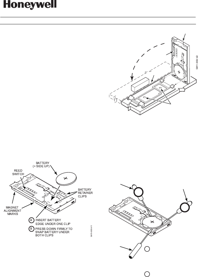
1. Install Battery by inserting one edge
under one of the two plastic battery
retainer clips, then pressing down firmly
to snap it beneath both clips; see
diagram.
2. Mount 5811 using double-faced tape
(supplied) by affixing it to the back of the
unit and mounting the unit in place. Use
screws (optional) if desired; see diagram.
Mount the magnet (supplied) near the
alignment marks on the case (see
Diagram).
REED
LATCH
R
O
T
A
T
E
T
O
C
L
O
S
E
MAGNET
MOUNTING
HOLES
MAX GAP
3/4"
CASE
TABS
3. Engage the case tabs (see diagram), then
rotate the housing to close. Engage latch
with firm pressure to close and lock.
BATTERY REMOVAL
1. Open housing by inserting a flat blade
screwdriver into latch and twisting gently.
2. Remove old battery cell using a small flat
screwdriver blade, as shown in the
diagram.
SCREWDRIVER
(NO)
5811-006-V1
SCREWDRIVER
(CORRECT)
SCREWDRIVER
(NO)
PLACE TIP OF FLAT SCREW
DRIVER BETWEEN EDGE OF
BATTERY AND PLASTIC CASE
AS SHOWN. POSITIONING
SCREWDRIVER AT ANY OTHER
CORNER MAY CAUSE DAMAGE
TO DEVICE.
CAREFULLY PRY UP WHILE
TWISTING TO REMOVE
BATTERY.
A
B
X
X
FEDERAL COMMUNICATIONS
COMMISSION STATEMENT: The user shall
not make any changes or modifications to the
equipment unless authorized by the
Installation Instructions or User Manual.
Unauthorized changes or modifications could
void the user's authority to operate the
equipment.
FCC / IC STATEMENT: This device
complies with Part 15 of the FCC Rules, and
RSS 210 of Industry Canada (IC). Operation
is subject to the following two conditions: (1)
This device may not cause harmful
interference (2) This device must accept any
interference received, including interference
that may cause undesired operation.
Cet appareil est conforme à la partie 15 des
règles de la FCC & de RSS 210 des
Industries Canada. Son fonctionnement est
soumis aux conditions suivantes: (1) Cet
appareil ne doit pas causer d' interferences
nuisibles. (2) Cet appareil doit accepter toute
interference reçue y compris les
interferences causant une reception
indésirable.
SPECIFICATIONS
Dimensions
2-1/8” (55mm) x 1-3/16” (30mm) x 1/4”
(7mm)
Operating Conditions
23° F (-5° C) to 120° F (50° C).
Relative Humidity 95%, (non-condensing)
Replacement Battery
Renata/Panasonic CR2032
WARRANTY INFORMATION
For the latest warranty information, please
visit:
www.honeywell.com/security/hsc/resources/
wa
REFER TO THE INSTALLATION INSTRUCTIONS
FOR THE RECEIVER/CONTROL WITH WHICH THIS
DEVICE IS USED FOR DETAILS REGARDING
LIMITATIONS OF THE ENTIRE ALARM SYSTEM.
2 Corporate Center Drive, Suite 100
P.O. Box 9040, Melville, NY 11747
Copyright © 2011 Honeywell International Inc.
www.honeywell.com/security
Ê800
Ê800Ê800
Ê800-
--
-03928V1dŠ
03928V1dŠ03928V1dŠ
03928V1dŠ
800-03928V1 8/11 Rev. A