Ademco 8DL5816OD-1 Wireless Outdoor Sensor User Manual 5816OD Wireless Outdoor Sensor
Honeywell International Inc. Wireless Outdoor Sensor 5816OD Wireless Outdoor Sensor
Ademco >
manual
5816OD Wireless Outdoor Sensor – Quick Installation Guide
For Online Support visit: http://www.security.honeywell.com/hsc/resources/MyWebTech/
WARRANTY For the latest warranty information go to: http://www.security.honeywell.com/hsc/resources/wa/
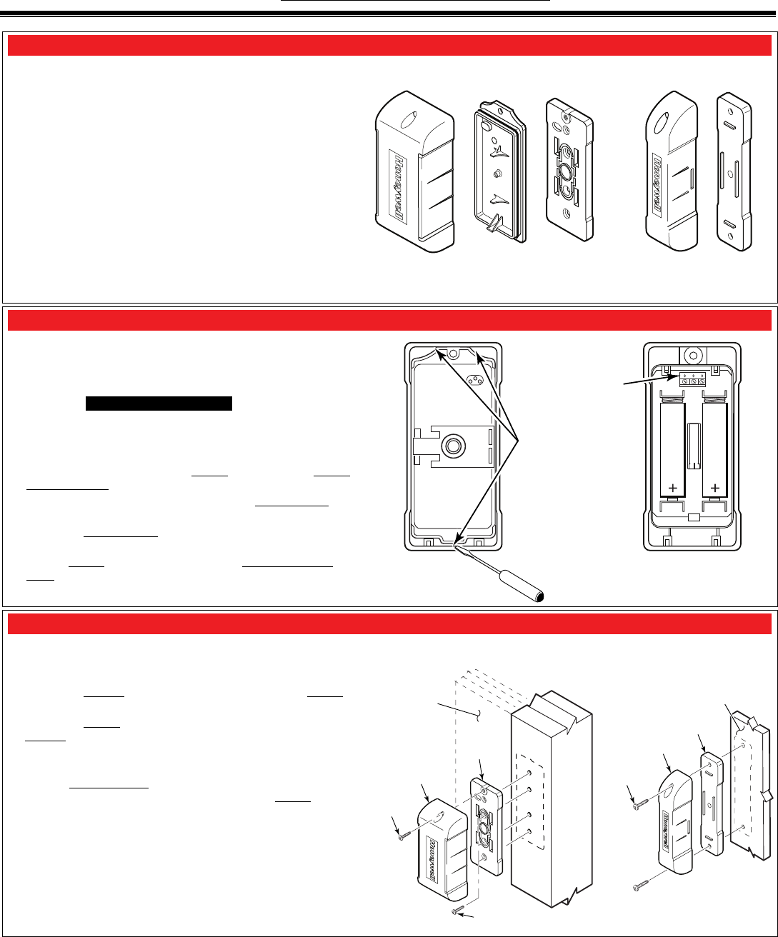
General Information and Component Identification
The Honeywell 5816OD Wireless Outdoor Sensor (referred to as
the Sensor) brings the convenience of wireless technology to the
outdoors. The major features are:
Weatherized security protection for an outdoor environment.
Great for sheds, barns, garages, pool gates, fences, and rural
mailbox (notifications).
Versatile mounting options on flat and round materials.
Cover and rear tamper detection.
Can be painted to coordinate with mounting surface.
Operating temp: – 40 to +50° C (– 40 to +122° F) at
RH of 100% (rain, snow).
Maximum Magnet Gap:
Wood: 1.75 inches
Metal: 1.25 inches
COMPONENT IDENTIFICATION
5816OD-001-V0
SENSOR
MOUNTING
PLATE MAGNET
MAGNET
SPACER
SENSOR
SEALING
COVER
Installing / Replacing the Batteries
IMPORTANT:
Always change both batteries. Do not mix weak batteries with
new batteries.
Use two (2) lithium 1.5VDC AA cells. (For best life, use
Eveready's Energizer Ultimate LITHIUM AA batteries,
Honeywell part number 462)
OBSERVE BATTERY POLARITY.
Battery Replacement:
1. Remove cover screw and swing Sensor to remove from Sensor
Mounting Plate.
2. Use screwdriver in any pivot point and pry Sealing Cover off.
Replace batteries.
3. Orient the Sealing Cover so the screw hole lines up with the
screw hole in the sensor cover, and press to close.
4. Engage Sensor tabs into mating holes in Sensor Mounting
Plate and swing closed. Secure with cover screw.
5816OD-002-V0
PRY
POINTS
TERMINAL BLOCK
FOR EXTERNAL
CONTACT SWITCH
Mounting Guidelines
This device is intended for vertical surfaces (to be mounted at a
sufficient height) where snow, ice and water buildup will not
interfere with its operation.
Mount the Magnet on the magnet sensing side of the Sensor as
identified by the side ribs on the Sensor.
Mount the Sensor on a stationary surface, and mount the
Magnet on the moveable surface.
When used on wooden sheds and barns, mount the sensor and
magnet on the inside of the structure.
Use the Magnet Spacer when mounting on metal surfaces; or
if needed to achieve proper alignment with the Sensor.
Use screws suitable for the material being fastened to.
FLAT SURFACES
COVER
SCREW
MOUNTING
SCREW (4)
5816OD-003-V0
MAGNET
MAGNET
SPACER
MOUNTING
SCREW (2)
SENSOR
SENSOR
MOUNTING
PLATE
FENCE GATE
SEE THE BOTTOM OF PAGE 2 FOR FCC & IC
STATEMENTS
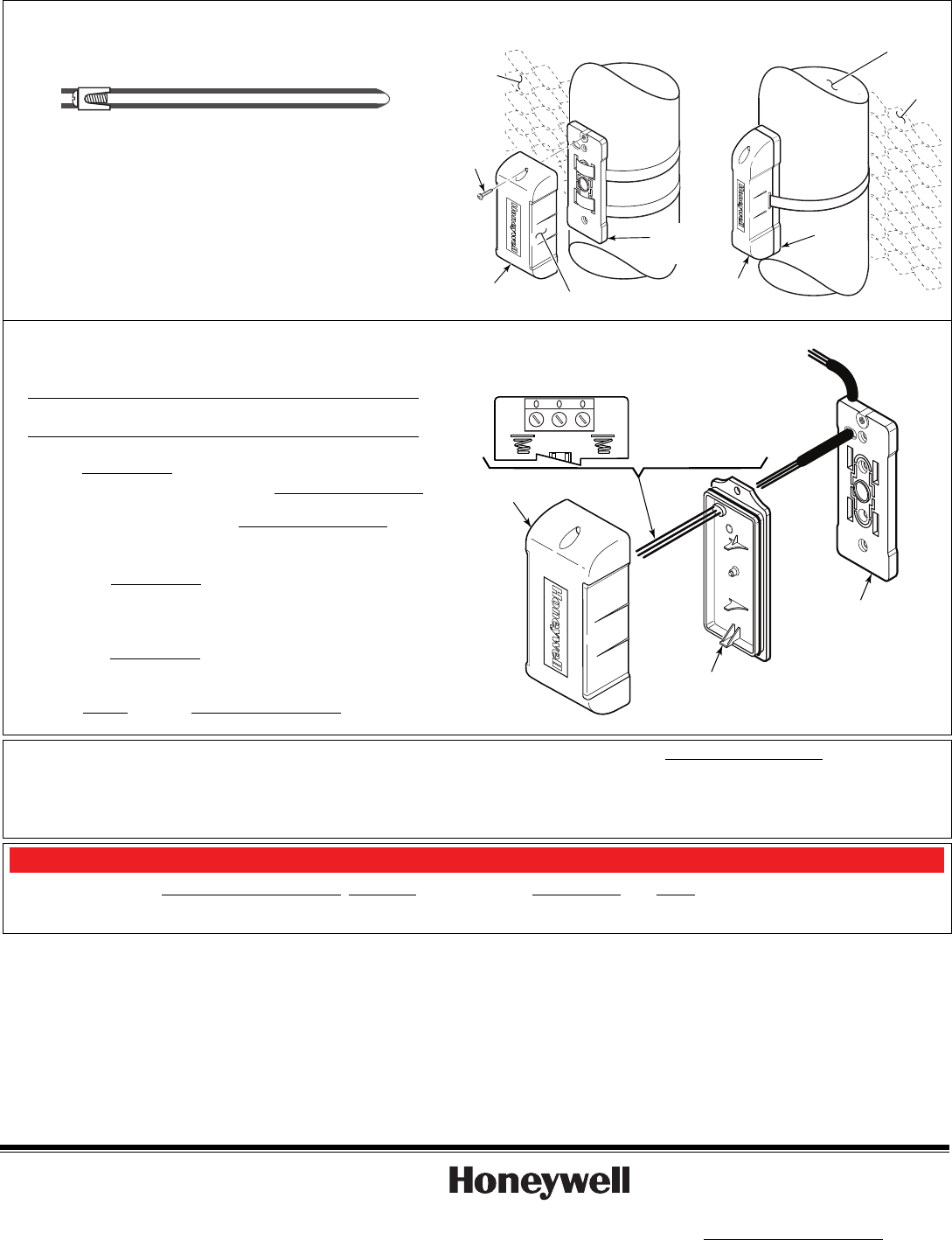
Curved Surfaces:
Suggested mounting hardware such as the strap ties and cable
ties are not supplied.
Mount using self locking stainless steel strap ties.
5816OD-005-V0
Self Locking Stainless Steel Strap Tie
Alternately you can use extra heavy duty Nylon 6/6 UV and
Temperature Rated cable ties
(0.5 inch wide).
If desired you may use screws in addition to the ties.
CURVED SURFACES
5816OD-004-V0
MAGNET
SENSOR
GATE
POST
GATE
MAGNET
SENSING
SLIDE
COVER
SCREW
FENCE
MAGNET
SPACER
SENSOR
MOUNTING
PLATE
ROUTING EXTERNAL WIRING – Optional for use with external
closed contact switches, such as the Honeywell N7945-2GY:
Note: Use minimum of 22AWG jacketed cable. The contact
switch must be a Form C (SPDT) type.
UL – The wired contact must be less than 3 feet from the
transmitter.
1. Strip cable jacket back 4-inches to allow enough slack to
remove Sealing Cover when changing batteries.
2. Pass cable through the access hole in Sensor Mounting Plate.
Use cable notch on mounting plate to pass jacketed portion of
cable through. Then attach the Sensor Mounting Plate.
3. Route cable to the external contact switch and fasten at
intervals to secure cable.
4. Remove the Sealing Cover and thread wires through the
rubber wire seal. If installed, REMOVE ANY BATTERIES.
5. Connect wires to terminal block in battery chamber, then
INSTALL the batteries.
6. Replace the Sealing Cover. (Note, orient the cover so the screw
hole lines up with the screw hole in the sensor cover, and press
to close.)
7. Engage Sensor tabs into Sensor Mounting Plate mating holes
and swing closed. Secure with cover screw.
SENSOR
SENSOR
MOUNTING
PLATE
SEALING
COVER
5816OD-006-V0
TO EXTERNAL
CONTACT SWITCH
CONNECT WIRES
TO TERMINAL BLOCK
IN BATTERY CHAMBER
CLOSED
OPEN
COMMON
PAINTING THE SENSOR:
The sensor and magnet may be painted to coordinate its color with the mounting surface. Use
only paints that are made for plastic and follow the manufacturer’s direction for preparing the
plastic and applying the paint. Observe the required drying and curing times.
DO NOT USE METALLIC PAINT COLORS.
Recommended Paints:
Krylon® "Fusion for Plastic"
Rust-Oleum® "Plastic"
Dupli-Color® "Vinyl & Fabric Coating"
Programming the Control Panel
You must program the transmitter's serial number, input type (RF Supervised), response type, and loop # in the control panel. (Either or both
loops may be used. Loop # 2 is for the magnet sensing, and Loop # 1 is for the external contact switch.) Refer to the control panel’s instructions
for further details. Note: The transmitter's serial number may be found on the carton, and in the Battery Chamber.
FCC / IC STATEMENT
This device complies with Part 15 of the FCC rules and RSS 210 of Industry Canada. Operation is subject to the following two conditions: (1) This
device may not cause harmful interference, and (2) This device must accept any interference received, including interference that may cause
undesired operation.
Cet appareil est conforme à la partie 15 des règles de la FCC & de RSS 210 des Industries Canada. Son fonctionnement est soumis aux conditions
suivantes: (1) Cet appareil ne doit pas causer d' interferences nuisibles. (2) Cet appareil doit accepter toute interference reçue y compris les
interferences causant une reception indésirable.
FEDERAL COMMUNICATIONS COMMISSION STATEMENT
The user shall not make any changes or modifications to the equipment unless authorized by the Installation Instructions or User’s Manual.
Unauthorized changes or modifications could void the user’s authority to operate the equipment.
Ê800-04494UŠ
800-04494 6/10 Rev. A
2 Corporate Center Drive, Suite 100
P.O. Box 9040, Melville, NY 11747
Copyright 2010 Honeywell International Inc.
www.honeywell.com/security