Ademco 8DL5816XT1 Window Sensor Transmitter User Manual 2
Honeywell International Inc. Window Sensor Transmitter 2
UserManual.wiki
>
Ademco
>
8DL5816XT1 User Manual
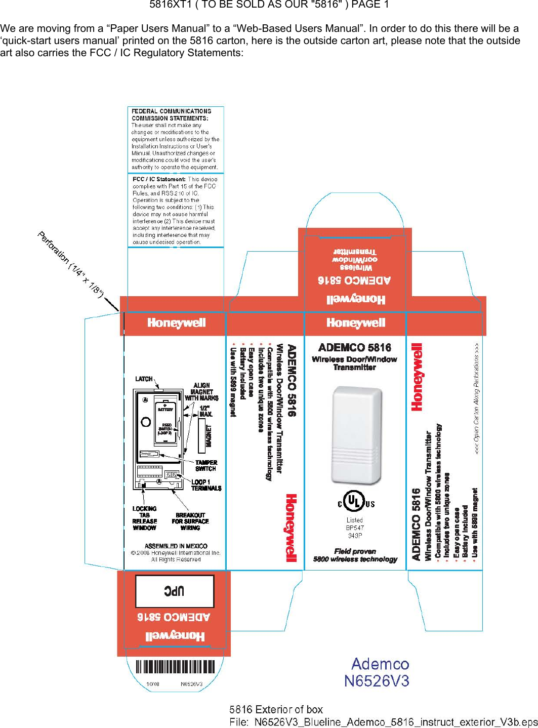
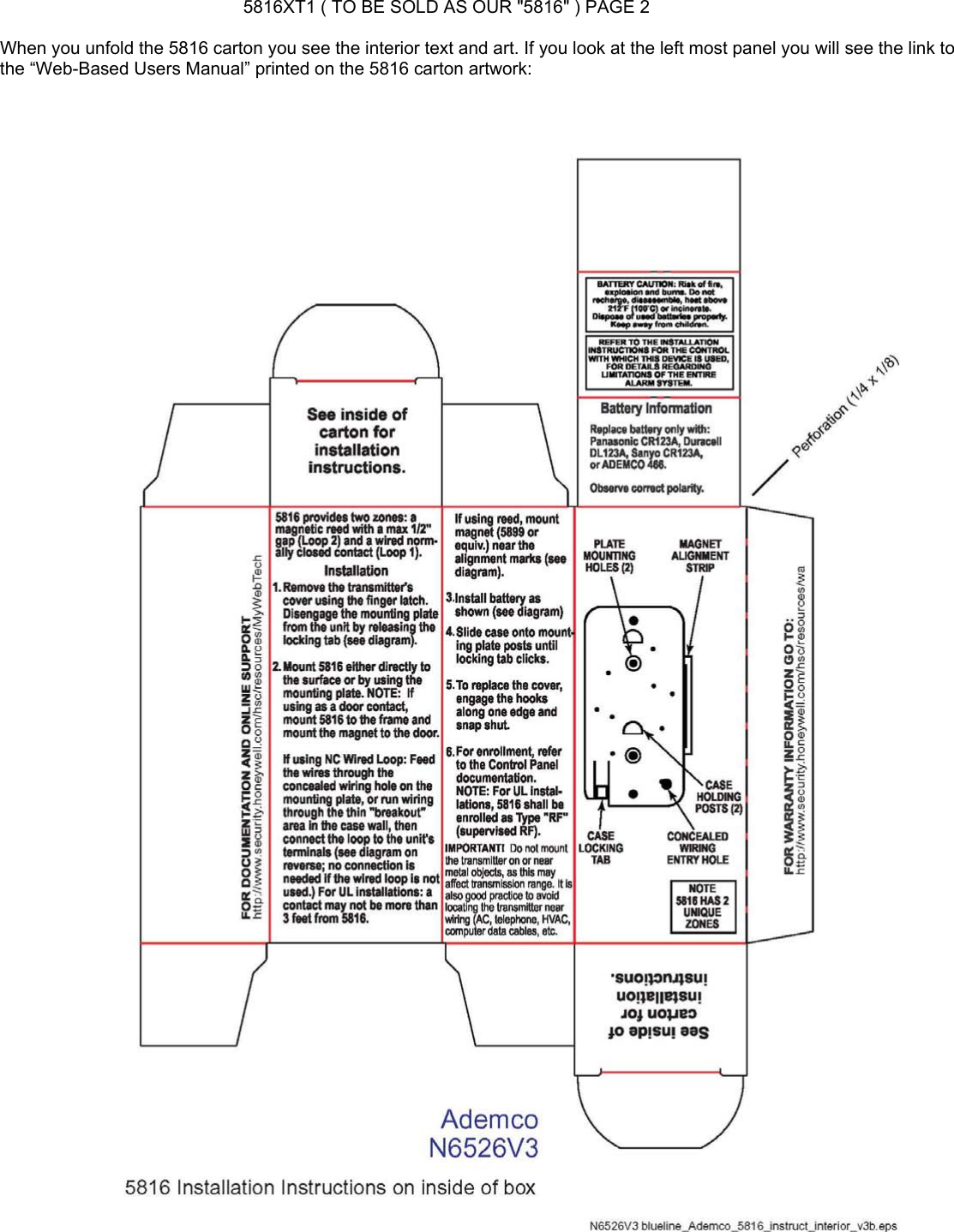
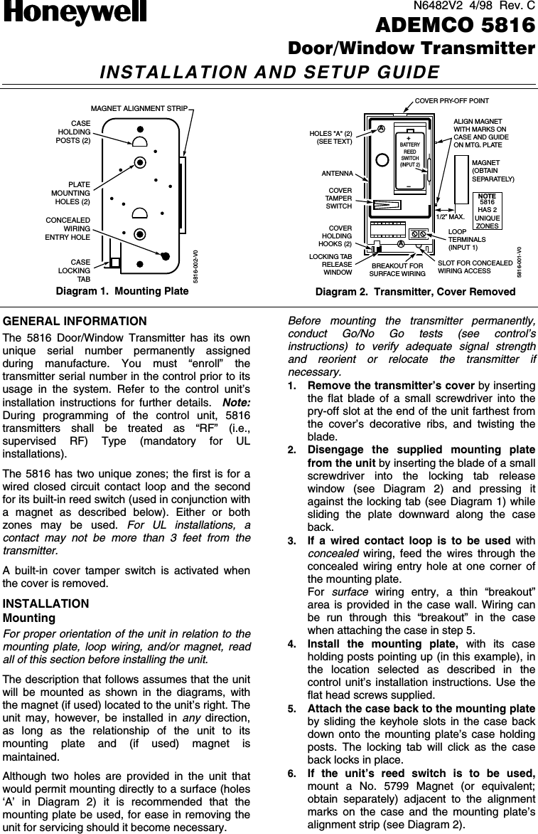
Users Manual
Navigation menu
Upload a User Manual
Namespaces
Wiki Guide
HTML
PDF
Info
Views
User Manual
Discussion / Help
Navigation