Ademco 8DL5817CB-2 Wireless Commercial / Household Transmitter User Manual K5623V2 RevA ii
Honeywell International Inc. Wireless Commercial / Household Transmitter K5623V2 RevA ii
Ademco >
manual

K5623V2 10/07 Rev. A (Preliminary)
LIMITED WARRANTY
Honeywell International Inc., acting through its Security & Custom Electronics business ("Seller"), 2
Corporate Center Drive, Melville, NY, 11747, warrants its product(s) to be in conformance with its own
plans and specifications and to be free from defects in materials and workmanship under normal use and
service for 24 months from the date stamp control on the product(s) or, for product(s) not having a
manufacturer’s date stamp, for 12 months from date of original purchase unless the installation
instructions or catalog sets forth a shorter period, in which case the shorter period shall apply. Seller's
obligation shall be limited to repairing or replacing, at its option, free of charge for materials or labor,
any product(s) which is proved not in compliance with Seller's specifications or proves defective in
materials or workmanship under normal use and service. Seller shall have no obligation under this
Limited Warranty or otherwise if the product(s) is altered or improperly repaired or serviced by anyone
other than Honeywell factory service. Connection of any device(s) to a communicating bus of a Honeywell
security system (e.g., keypad bus, polling loop) other than those manufactured or approved by Honeywell
shall void this warranty. For warranty service, return product(s) transportation prepaid, to your local
authorized Honeywell representative.
THERE ARE NO WARRANTIES, EXPRESS OR IMPLIED, OF MERCHANTABILITY, OR FITNESS FOR A
PARTICULAR PURPOSE OR OTHERWISE, WHICH EXTEND BEYOND THE DESCRIPTION ON THE FACE
HEREOF. IN NO CASE SHALL SELLER BE LIABLE TO ANYONE FOR ANY CONSEQUENTIAL OR
INCIDENTAL DAMAGES FOR BREACH OF THIS OR ANY OTHER WARRANTY, EXPRESS OR IMPLIED, OR
UPON ANY OTHER BASIS OF LIABILITY WHATSOEVER, EVEN IF THE LOSS OR DAMAGE IS CAUSED BY
THE SELLER'S OWN NEGLIGENCE OR FAULT.
Seller does not represent that the product(s) it sells may not be compromised or circumvented; that the
product(s) will prevent any personal injury or property loss by burglary, robbery, fire or otherwise; or
that the product(s) will in all cases provide adequate warning or protection. Customer understands that a
properly installed and maintained alarm system may only reduce the risk of a burglary, robbery, fire, or
other events occurring without providing an alarm, but it is not insurance or a guarantee that such will
not occur or that there will be no personal injury or property loss as a result. CONSEQUENTLY,
SELLER SHALL HAVE NO LIABILITY FOR ANY PERSONAL INJURY, PROPERTY DAMAGE OR
OTHER LOSS BASED ON A CLAIM THAT THE PRODUCT(S) FAILED TO GIVE WARNING.
HOWEVER, IF SELLER IS HELD LIABLE, WHETHER DIRECTLY OR INDIRECTLY, FOR ANY LOSS
OR DAMAGE ARISING UNDER THIS LIMITED WARRANTY OR OTHERWISE, REGARDLESS OF
CAUSE OR ORIGIN, SELLER'S MAXIMUM LIABILITY SHALL NOT IN ANY CASE EXCEED THE
PURCHASE PRICE OF THE PRODUCT(S), WHICH SHALL BE THE COMPLETE AND EXCLUSIVE
REMEDY AGAINST SELLER.
This warranty replaces any previous warranties and is the only warranty made by Seller on this
product(s). No increase or alteration, written or verbal, of the obligations of this Limited Warranty is
authorized.
This device complies with Part 15 of FCC rules and RSS 210 of IC. Operation is subject to the
following two conditions: (1) this device may not cause harmful interference. (2) this device must
accept any interference received, including interference that may cause undesired operation.
Note: The user shall not make any changes or modifications to the equipment unless authorized by the
Installation and Setup Guide or User Guide. Unauthorized changes or modifications could void the user's
authority to operate the equipment.
UL For dry, indoor use only. Do not install in air-handling spaces.
ÊK5623V2PŠ
2 Corporate Center Drive, Suite 100
P.O. Box 9040
Melville, NY 11747
Copyright © 2007 Honeywell International Inc.
www.security.honeywell.com
Preliminary K5623V2 10/07 Rev. A
ADEMCO 5817CB
WIRELESS COMMERCIAL
/
HOUSEHOLD TRANSMITTER
INSTALLATION AND SETUP GUIDE
GENERAL INFORMATION
The 5817CB is a universal contact-monitoring transmitter that can be used with household and
commercial fire and burglary-initiating devices such as door/window contacts, motion and glassbreak
detectors, sprinkler water flow switches, tamper switches, post indicator valves, manual pull stations,
and remote duct detectors. Upon activation, it emits an RF signal to a control panel that sends a burglary
or fire alarm to a central station. The 5817CB has three unique input loops (zones). The first loop
(primary loop) is supervised and typically used for high-priority alarm reporting such as commercial fire
or burglary. It requires a 470K ohm end-of-line resistor to be placed across the sensor. The second loop is
the built-in, normally closed reed switch (used in conjunction with a magnet, as described below). The
third loop is another normally closed household burglary loop. All three loops may be used. A fourth
(automatically enrolled) loop contains two tamper switches to protect the 5817CB transmitter. A built-in
cover tamper switch is activated when the cover is removed. A unit tamper switch is activated if the unit
is separated from its mounting plate.
PROGRAMMING
The 5817CB has its own unique serial number permanently assigned during manufacture. You must
"enroll" this transmitter serial number in the control panel at some point prior to its usage in the alarm
system. Refer to the control panel's installation instructions for specific programming procedure. Note:
During programming of the control panel, program the 5817CB transmitter as Input Type "RF" (i.e.,
supervised RF) (mandatory for UL installations).
MOUNTING
For proper orientation of the unit in relation to its wall mounting plate and the loop wiring, read all of
this section before installing the unit. Signal strength may vary from location to location. Before mounting
the transmitter permanently, conduct Go/No Go tests (see control's instructions) to verify adequate signal
strength from this location. When a satisfactory location is found, make note of the position of the unit
on the wall, remove the battery and proceed with installation. The following mounting instructions
assume that the unit will be mounted as shown in the Figures. The unit may, however, be installed in
any direction, as long as the relationship of the unit to its mounting plate or tamper switch hold-down (if
used), is maintained.
The 5817CB is supplied with a tamper switch hold-down tab (connected to the mounting plate as shown in
Figure 1), for use when the wall mounting plate is not needed. Remove the tab with diagonal cutting
pliers.
The mounting plate, installed as described below, enables easy removal of the unit for servicing, should it
become necessary.
1. Remove the transmitter's cover by inserting the flat blade of a small screwdriver into the pry-off
slot at the bottom end of the unit on the right side closest to the cover's decorative ribs and twisting.
2. Disengage the supplied mounting plate from the unit by inserting the blade of a small
screwdriver into the mounting plate release hole (see Figure 3) and pushing the locking tab out (see
Figure 1). Slide the mounting plate downward along the case back. Note: For this application, the
alignment guide strip along one edge of the mounting plate serves no function and may be broken
away, if desired.
3. If concealed wiring is to be used, feed the wires through the concealed wiring entry hole at one
corner of the mounting plate (and/or case back). Surface wiring is discussed in Step 5 below).
4. Install the mounting plate, with its case-holding posts pointing up, in the location determined.
Use two flat head dry-wall screws. Note: To ensure proper operation of the unit's back tamper (when
it is separated from the mounting plate), the screws must be anchored to a wall stud or other solid
wood material. If the mounting plate will not be used, make note of the location of the tamper
switch hold-down as shown in Fig. 1 for the proper placing of the hold-down tab in Fig. 2.
5. If surface wiring is to be used, remove the knockout slot in the case back (located across from loop
3 terminal block). Surface wiring should enter through this knocked out space provided. Do not
connect the wiring to the terminal block(s) yet.
FCC STATEMENTS
- 2 - - 3 -
6. Attach the case back to the mounting plate by sliding the keyhole slots in the case back down onto
the mounting plate's holding posts. The locking tab will click as the case back locks in place. To
disengage the unit from an installed mounting plate, insert a small screwdriver into the
mounting plate release hole, push down to retract the locking tab, and push upward on the unit to
disengage from posts. If not using the mounting plate, it is necessary to remove the PC board
from the case back. Slide a small flat bladed screwdriver between the case back and PC board near
the board hold-down clip and carefully pry the board out.
7. In the area that was previously marked for the location of the mounting plate, (step 4), install the
hold-down tab with a 5/8” flat head dry-wall screw. The tab must be aligned with the corresponding
slot in the case back as shown in Figure 2. The tab as well as the case back must be anchored to a
wall stud or other solid wood material.
8. To reinstall the PC board into the case back, position the board onto the two retaining studs on one
side of the case back and snap the board into place. The hold-down tab must mate with the
corresponding cutout in the case back after case back is installed.
9. Reverse the procedure of the first three steps to complete reassembly of the unit.
10. Set the DIP switch (after the control panel has enrolled the transmitter's input IDs) for the desired
primary loop characteristics, as described in the table below.
PRIMARY LOOP OPTIONS TABLE
DIP SWITCH POSITION
SWITCH
SETTING 1 2 3 4
ON REPEATING TRANSMISSION
(every 4 sec.)
UPON PRIMARY LOOP FAULT
Use for high priority
alarm, such as fire.
OFF SINGLE TRANSMISSION
PER PRIMARY LOOP CHANGE-OF-
STATE
SWITCH
MUST
ALWAYS BE
IN THE
ON
POSITION
SWITCH
MUST
ALWAYS
BE
IN THE
ON
POSITION
SWITCH
MUST
ALWAYS BE
IN THE
OFF
POSITION
Notes: a. In order for the control panel to enroll the transmitter, the DIP switches must be
set to OFF – ON – ON – OFF (see Figure 3).
b. The Auxiliary loops are not affected by the DIP switch settings.
UL REQUIREMENT
1. If using one of the panel revisions shown in the following table, and programming the 5817CB as an
Entry/Exit zone, you must enroll the tamper loop (loop 4) as a separate zone, programmed for 24-
hour response (e.g., Zone type 5 Trouble-by-day/Alarm-by-night).
Model # Rev. EPROM P/N
FA1600C 8 (WAVIS150FA-18)
Vista-32FB 3 (WAVIS32FB-13)
Vista-128FB 4 (WAVIS128FB-14)
Vista-128B 3 (WAVIS128B-13)
2. For UL Commercial Burglary installations, this transmitter must be used in conjunction with the
5881ENHC RF Receiver.
WIRING CONNECTIONS
Connect the loop wiring to the unit's terminals before installing the battery (see Figure 3).
Notes: a. Primary loop 1 is a supervised loop and must have an end-of-line (EOL) resistor (470K
ohms, supplied) placed across the last sensor. Additionally, for Primary loop 1, a contact
device may not be installed more than 20 feet from the transmitter.
b. If loop 2 is not going to be used, the magnet is not necessary.
c. If loop 3 is not going to be used, no connection is needed across its terminals. For UL
household burglary and fire installations, the loop 3 contact device (if used) may not be
more than 3 feet from the transmitter.
BATTERY INSTALLATION/REPLACEMENT
1. Remove the transmitter's cover as described in Mounting Step 1.
2. Observe correct polarity and insert the battery provided into the battery holder (see
Figure 3). Take care not to bend the antenna.
Note: Replace battery only with: Duracell DL123A, Panasonic CR123A, Ademco 466 or Varta
CR123A.
Risk of fire, explosion, and burns. Do not recharge, disassemble, heat above 212°F
(100°C), or incinerate. Dispose of used batteries promptly. Keep away from children.
3. To replace the cover, engage the hooks along the top edge and snap shut.
SPECIFICATIONS
Dimensions: 1-9/16"W x 3-1/2"H x 1-3/16"D (40mm x 89mm x 30mm)
Battery: 3V Lithium (see BATTERY INSTALLATION/REPLACEMENT).
UL Listings:
Commercial Fire…….UL864 Household Burg……..UL1023
Household Fire………UL985 Commercial Burg……UL365, UL609, UL1076, UL1610
This is a CLASS B DEVICE
TESTING
Regular maintenance and inspection (at least annually) by the installer and frequent testing by the user
are vital to continuous satisfactory operation of any alarm system. For testing procedures refer to the
User Guide or Installation and Setup Guide for the system control panel.
The installer should assume the responsibility of developing and offering a regular maintenance program
to the user, as well as acquainting the user with the proper operation and limitations of the alarm system
and its component parts. Recommendations must be included for a specific program of frequent testing
(at least weekly) to insure the system's operation at all times.
FOR DETAILS ON LIMITATIONS OF THE ENTIRE ALARM SYSTEM, REFER TO THE
CONTROL PANEL'S INSTALLATION AND SETUP GUIDE FOR THE RECEIVER/CONTROL
WITH WHICH THIS DEVICE IS USED.
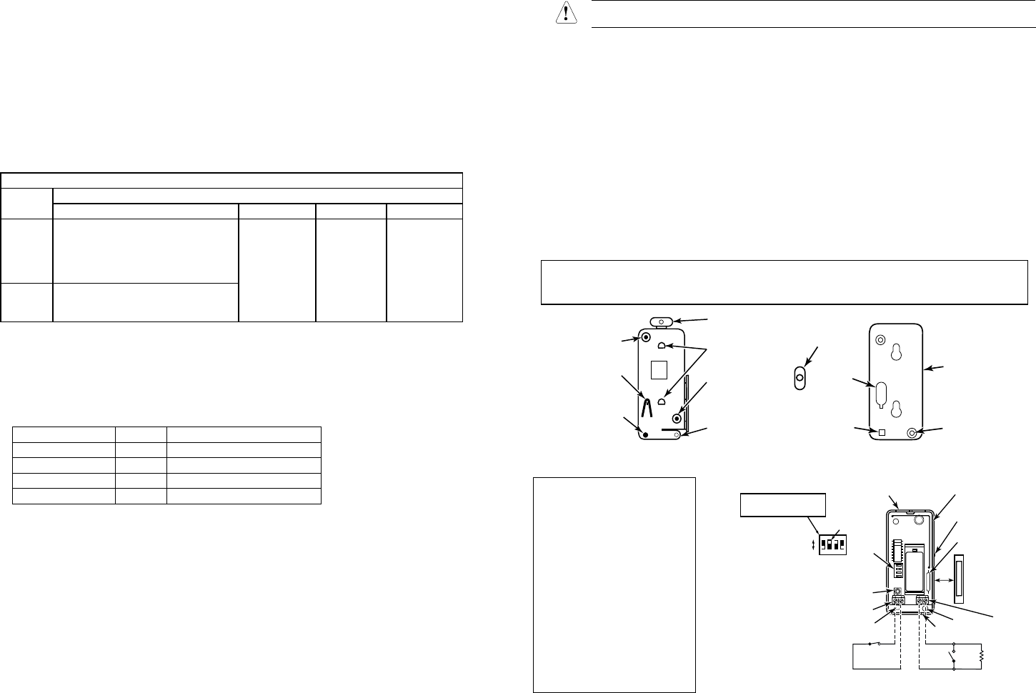
5817CB-001-V1
MOUNTING
PLATE
HOLE CASE
HOLDING
POSTS
CONCEALED
WIRING
ENTRY
HOLE
MOUNTING
PLATE HOLE
TAMPER SWITCH
HOLD DOWN
LOCKING
TA B
HOLD-DOWN
TA B
Figure 1. Mounting Plate
5817CB-001-V0
TAMPER SWITCH
HOLD-DOWN TAB
CASE BACK
CONCEALED
WIRING
ENTRY HOLE
MOUNTING
HOLES (2)
INSTALL
IN LINE WITH
CUT-OUT
IN CASE BACK
Figure 2. Case Back
NOTE: For UL commercial
and household fire
installations, only one initiating
device may be connected to
this transmitter. For UL
commercial burglary
installations, multiple initiating
devices may be used as long
as the devices all serve the
same function, such as
door/window contacts, motion
or glassbreak detectors. All
initiating devices must be
located within the same room.
+
–
BATTERY
5817CB-002-V1
DIP
SWITCH
COVER
HOLDING
SLOTS (2) ANTENNA
COVER
TAMPER
SWITCH
COVER
PRY-OFF
POINT
MOUNTING
PLATE
RELEASE
1/2"
MAX.
N.O.
CONTACT
DEVICE
N.C.
CONTACT
DEVICE
LOOP 3
TERMINALS
(AUX)
ALIGN MAGNET
WITH MARKS ON
CASE (2 PLACES)
MAGNET
(OBTAIN
SEPARATELY)
LOOP 2
REED SWITCH
(AUX)
PRIMARY
LOOP 1
TERMINALS
DIP SWITCH FOR PRIMARY LOOP OPTIONS
(SEE SETTINGS TABLE)
SHOWN SET FOR: 1. SINGLE TRANSMISSION
NOTE: SW2 MUST BE ON
ON
OFF
ON
1 2 3 4
WHITE AREA
INDICATES
SWITCH HANDLE
THE DIP SWITCHES MUST BE
SET AS SHOWN DURING
ENROLLMENT BY THE CONTROL
SLOT FOR
CONCEALED
WIRING ACCESS
SW3 MUST BE ON
SW4 MUST BE OFF
EOLR 470K ohms
Figure 3. 5817CB Transmitter, Top Cover Removed