Ademco 8DL5818MN Door Window Security Transmitter User Manual K9485 ii
Honeywell International Inc. Door Window Security Transmitter K9485 ii
Ademco >
Contents
- 1. II with FCC Part 15 Statements
- 2. user manual
II with FCC Part 15 Statements
K9485 02/04 Rev
A
ADEMCO 5818MN
Recessed Door Transmitte
r
INSTALLATION AND SETUP GUIDE
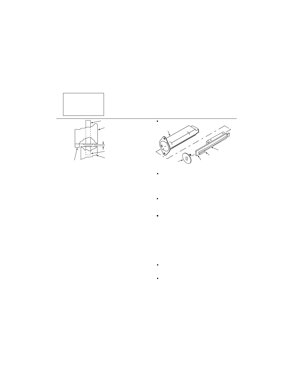
EXTERNAL PHYSICAL BARRIER
(e.g. MOLDING)
1/2" MAXIMUM
MAGNET
"IN" SIDE OF
DOOR
5818MN TRANSMITTER
5818MN-002-V1
FRAME OF
DOOR
Figure 1: Door Installation
GENERAL INFORMATION
The ADEMCO 5818MN Recessed Door Transmitter is
a reed switch, magnetic contact sensor that provides
concealed protection for a door. It is intended for use
only with alarm systems that support 5800 series
devices.
The transmitter is powered by an AAA Alkaline battery
that is easily replaced when a low battery condition is
indicated by the control panel.
PROGRAMMING THE ID NUMBER
Each 5818MN has its own unique identification code
(serial number) permanently assigned during
manufacture.
The control panel is required to “enroll” the
transmitter’s ID during installation of the alarm system.
Note:
During programming of the control panel,
5818MN transmitters must be enrolled as an "RF"
(i.e., supervised RF) Type 3, Loop 1 (
mandatory for
UL installations
).
The 5818MN is a single zone transmitter.
PRELIMINARY
Read all of this and the next section before installing
the unit.
1. Select a location for the transmitter on the
frame of the door (never on the
hinged
edge) to
be protected.
Do not use on metal frame doors.
TRANSMITTER
CASE
ANTENNA
END CAP
REED
SWITCH
PC BOARD
5818MN-001-V0
Figure 2: Battery/Transmitter Assembly
The transmitter will require a 3/4“ diameter hole
in the edge of the frame, at least 3” deep. Its
magnet will need a 3/8” diameter hole in the
edge of the door at least 1/2” deep. BEFORE
DRILLING ANY HOLES, SEE STEP 2 BELOW
AND
MOUNTING
ON THE NEXT PAGE.
The preferred direction of mounting is vertical,
although the 5818MN may be mounted in
any
direction if satisfactory reception of its
transmissions is obtained.
A physical barrier (e.g., a molding strip on the
door frame) should be present to protect against
defeat of the contact from outside the premises.
2. Before drilling any holes, tape the transmitter and
magnet in their approximate locations (with battery
installed and unit together as described under
BATTERYINSTALLATION/REPLACEMENT
(below) and conduct Go/No Go tests (refer to
control panel’s instructions) to verify adequate
signal strength. Reorient or relocate transmitter if
necessary.
Make sure that no more than 1/2” gap exists
between the faces of the transmitter and magnet
cases when they are installed and set.
When installed, an alarm signal must be
obtained before a separation of 2” is reached
as the door is opened.
PRELIMINARY
6/26/03..tp
updated 2/05/04

MOUNTING
1. Mark the selected location for the transmitter on
the frame of the door.
2. Mark the location for the magnet on the door,
directly opposite the transmitter location.
Caution
: Before drilling any holes, make sure that
successful Go/No Go transmission/reception tests
have been conducted as called for in step 2 of the
PRELIMINARY section
on the first page.
3. Drill holes at the locations marked, for the
transmitter (3/4” diameter, at least 3” deep) and
magnet 3/8” diameter, at least 1/2” deep).
4. Insert the transmitter and magnet cases into
their respective holes, so that their ends are flush
with the surface.
DO NOT hammer in place with hard blows. If
necessary, tap
gently
with a rubber mallet or
wood block.
The transmitter case may be secured by two #4
flat head, self-tapping screws via the holes in its
mounting flanges, or the flanges can be
snapped off by scoring around them first with a
sharp knife.
If necessary, either case may be secured with a
suitable adhesive.
NOTE: A closure plug is supplied to cover an empty
transmitter hole if it becomes necessary to relocate
the transmitter.
BATTERY INSTALLATION/REPLACEMENT
1. Remove the transmitter’s end cap by inserting
the flat blade of a screwdriver in the cap’s slot and
turning slightly counterclockwise.
2. Slide the transmitter PCB assembly out of its
case,
taking care not to bend the antenna during
this step or later.
3. Remove the old battery, if replacing it.
4. Observe correct polarity and insert the fresh
battery into the battery holder (position the battery
as shown in Figure 2).
5. Slide the PCB assembly back into its case,
battery end first (
the reed switch end must be close
to the end cap
).
6. Replace the end cap. Line up the projections on
the cap with the openings at the edge of the case.
Press the cap gently against the PCB and turn the
cap (via its slot) slightly clockwise, thereby locking
it in place.
SPECIFICATIONS
Dimensions: ..................... 3.0” H x 0.66” W x 0.8” D
(76.2mm) x (14.0mm) x (20.3mm)
Gap (xmtr to magnet): .................0.5” (12.7mm) max
Operating temperature:........ 0 - 50 C, non-condensing
Battery: ................................ 1.5VDC, AAA, Alkaline
(Duracell MX2400, Panasonic AM-4PI,
Eveready Energizer EN92)
FCC STATEMENT FCC ID: CFS8DL5818MN
This device complies with Part 15 of the FCC Rules. Operation is subject to the following two conditions: (1) This
device may not cause harmful interference, and (2), this device must accept any interference received, including
interference that may cause undesired operation. CANADA: 1748A5818MN
FOR WARRANTY INFORMATION AND LIMITATIONS OF THE ENTIRE ALARM SYSTEM, REFER TO
THE INSTALLATION INSTRUCTIONS FOR THE CONTROL WITH WHICH THIS DEVICE IS USED.
¬.1l
K9485 2/04 Rev A
165 Eileen Way, Syosset, NY 11791
Copyright 2004 Honeywell International Inc.
www.security.honeywell.com