Ademco 8DL5828V Security Transceiver User Manual K0020V3 RevA
Honeywell International Inc. Security Transceiver K0020V3 RevA
UserManual.wiki
>
Ademco
>
8DL5828V User Manual
manual
Navigation menu
Upload a User Manual
Namespaces
Wiki Guide
HTML
PDF
Info
Views
User Manual
Discussion / Help
Navigation
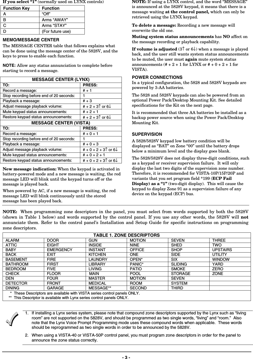
![K0020V3 5/10 Rev. AADEMCO 5828/5828VWireless Bidirectional Fixed-Word KeypadsINSTALLATION AND SETUP GUIDE GENERAL INFORMATION The ADEMCO 5828 and 5828V are wireless, bidirectional, fixed-word, keypads that may be used in conjunction with LYNX and VISTA series residential control panels. VISTA systems require use of either a 5883 Transceiver (micro P/N WAK5119-X, where X = 3 or higher), 6150RF Keypad/ Transceiver (PC board P/N SA6150RFAS-T3 or higher), or 6160RF Keypad/Transceiver. The 5828/5828V keypads are not compatible with commercial control panels that have three-digit zone numbers (e.g., VISTA128BP). Both keypads provide: • Four programmable special function keys • Wall-mount plate for easy removal of the keypad and battery replacement • Optional Desktop mount /AC adapter kit, ADEMCO P/N 5828DM) • Battery-powered with 3-AA batteries The 5828V keypad additionally provides: • Memo/Message center • Voice Response – system status, zone information, and alarms with zone information • Stored Message LED indication • Built-in microphone and speaker NOTES: • The 5828/5828V cannot be used as the primary system keypad, and may not be used to program or test any security system. All systems require a hardwired keypad (or Compass Downloader) to do so. Once programmed, the 5828/5828V can be used to initiate all common functions of a fixed English keypad. 1OFF4MAX7INSTANTREADY2AWAY5TEST8CODE03STAY6BYPASS9CHIME#ARMEDREADY5828-00-001-V0ABCD 5828 Keypad with Front Cover Removed 5828V-00-002-V01OFF4MAX7INSTANTREADY2AWAY5TEST8CODE03STAY6BYPASS9CHIME#DCBA 5828V Keypad with Front Cover Removed Operation (See NOTE below) 1. Battery-Powered Operation: When powered by battery, the keypad activates when any key is pressed. When the [✱] key is pressed, the keypad sends a system status request, and displays and/or annunciates the present status transmitted by the system. 2. AC-Powered Operation: When powered by AC, the keypad remains active at all times. Any change in system status will cause the display to automatically turn on (if blank) and display/annunciate the new status. If AC power is lost, the keypad will revert to battery-powered operation until AC power is restored and a new status request is made ([✱] key). NOTE: Whether the unit is powered by battery or AC, the 5828/5828V may take up to 5 seconds to display and/or annunciate the new status after pressing the [✱] key. WALL MOUNTING Before mounting the 5828 & 5828V permanently, determine a good RF location as follows: • If interfacing to a LYNX panel, try communicating with the panel from different locations. • If interfacing to a VISTA panel, perform a Go/No Go test from the panel. Refer to the Go/No Go test mode in the Installation and Setup Guide for the panel. Avoid mounting locations on or near large metal objects, since these can decrease the transmission range or block transmissions. • Secure the mounting plate to the wall, using proper sized hardware through the six mounting holes. • Plug the cord from the optional power pack into the keypad’s DC input connector, and route the wires through the wire guides on the back of the keypad. • Position the keypad over the mounting plate and slide down, engaging the four retaining clips on the plate with the receptacles on the keypad. DESKTOP MOUNTING For full portability, the keypad may be placed in any conven-ient, RF-suitable location and operated in its battery-powered mode, or near an AC outlet to be powered by the optional Power Pack/Desktop Mounting Kit, ADEMCO P/N 5828DM. BATTERY INSTALLATION OR REPLACEMENT CAUTION: Remove the AC/DC power connector from the keypad (if applicable), before attempting to install or replace the batteries. 1. Separate the keypad from its mounting plate by sliding the keypad up and away from the mounting plate. 2. Open the battery compartment door to expose the batteries. FCC & IC AGENCY STATEMENTS ARE ON PAGE 4](https://usermanual.wiki/Ademco/8DL5828V/User-Guide-1283168-Page-1.png)
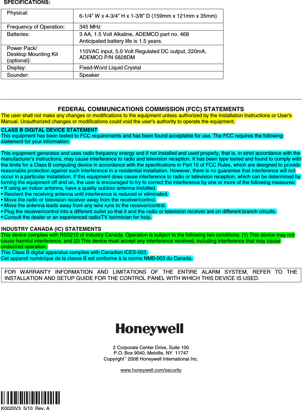
![- 2 - 3. Install or replace the 3-1.5 Volt AA batteries in the battery compartment. Always replace all three batteries at once to ensure normal operation of the keypad over the anticipated battery lifetime. Make sure that battery positive (+) and negative (–) terminals are properly oriented with the battery spring clip connections. Refer to battery placement graphic below. batt_case-001-V0AA BATTERYAA BATTERYAA BATTERY Battery Compartment 4. Reattach the keypad to its mounting plate by aligning the four mounting holes in the keypad case back with the four mounting clips on the mounting plate. Lower the keypad onto the clips. PROGRAMMING The following two items must be programmed in the keypad by the installer. • House ID Code (Step 1 in Installer Programming mode)* • System Type (Step 2 in Installer Programming mode) *The same House ID Code must also be programmed in the control panel. Programming a different House ID will disable communication. Installer Programming Enter the program mode by pressing the [1] and [3] keys simultaneously for five (5) seconds. The display alternately flashes “00” and two dashes (--). NOTES: • Entering a value other than one specified in the following steps may cause unpredictable results. • This keypad exits programming mode 15 seconds after the last key is pressed. Pressing any key will extend the 15-second active time. If the unit times out before you have pressed the star (✱) key to save a programmed value, you will need to re-enter the Programming mode and reprogram the option. STEP ACTION DISPLAY 1. Press [1] (House ID Code) (10 = default) Enter the two-digit house code (01-31) Press [✱] to continue. Alternately flashes “t1” and the 2-digit house code. 2. Press [2] (System Type). Press (1) for VISTA Press (2) for LYNX (2 = default) Press [✱] to continue. Alternately flashes “t2” and (1 or 2) 3. Press [3] (Exit Delay) Press 0-9 in 15 second increments. Example: If you press 3, exit delay would be 3 times 15 seconds for a total of 45 seconds. NOTE: The Exit Delay programmed here should match the Exit Delay programmed in the control panel. (0 = default) Press [✱] to continue. Alternately flashes “t3” and value selected. 4. (5828V only) Press [4] (Voice enable/disable). Press (0) to disable. Press (1) to enable. (1 = default) Press [✱] to continue. Alternately flashes “t4” and (0 or 1) 5. Press [5] (Wireless Protocol). Press [1] for original LYNX controls Press [2] for LYNXR, LYNXR-EN, or VISTA controls (2 = default) Press [✱] to continue. Alternately flashes “t5” and (1 or 2) 6. Press [6] (Function Key Select). Press [0] for Panic Key Press [1] for Single-button arming NOTE: The programming here must match the programming of the control panel to simplify end user operation. (1 = default.) Press [✱] to continue. Alternately flashes “t6” and (0 or 1) 7. Press [7] (Restore Defaults). Press [1] to restore factory settings. Press [✱]. Exit programming mode. Displays “EE” Exiting Programming Mode You can exit programming mode by pressing the [✱] key whenever the small 00 and (- -) are alternately displayed. Programming or Changing a User Code (Required if using Quick Arm function on LYNX or VISTA) Enter user program mode by pressing the [7] and [9] keys at the same time until the display flashes double dashes (- -). Enter the desired 4-digit user code that matches a user code programmed in the control panel. There will be no display of the user code entered. Press the [✱] key to place the 4-digit code in memory and exit the user program mode. SPECIAL FUNCTION KEYS As shown in the figures on page 1, each keypad contains four Special Function keys (A, B, C, D) that may be programmed to execute the commands shown below. NOTE: The Function Key Select setting in Step 6 of the INSTALLER PROGRAMMING procedure above determines the operation of the Special Function keys A, B, C, and D as follows: If you select “0” Function Key Function Message Sent to Control A [1] + [✱] (Alarm zone 95) B [✱] + [#] (Alarm zone 99) C [3] + [#] (Alarm zone 96) D (Not used for panic alarms) NOTE: Do NOT use the 5828V for silent panic operation because the keypad itself is not silent.](https://usermanual.wiki/Ademco/8DL5828V/User-Guide-1283168-Page-2.png)