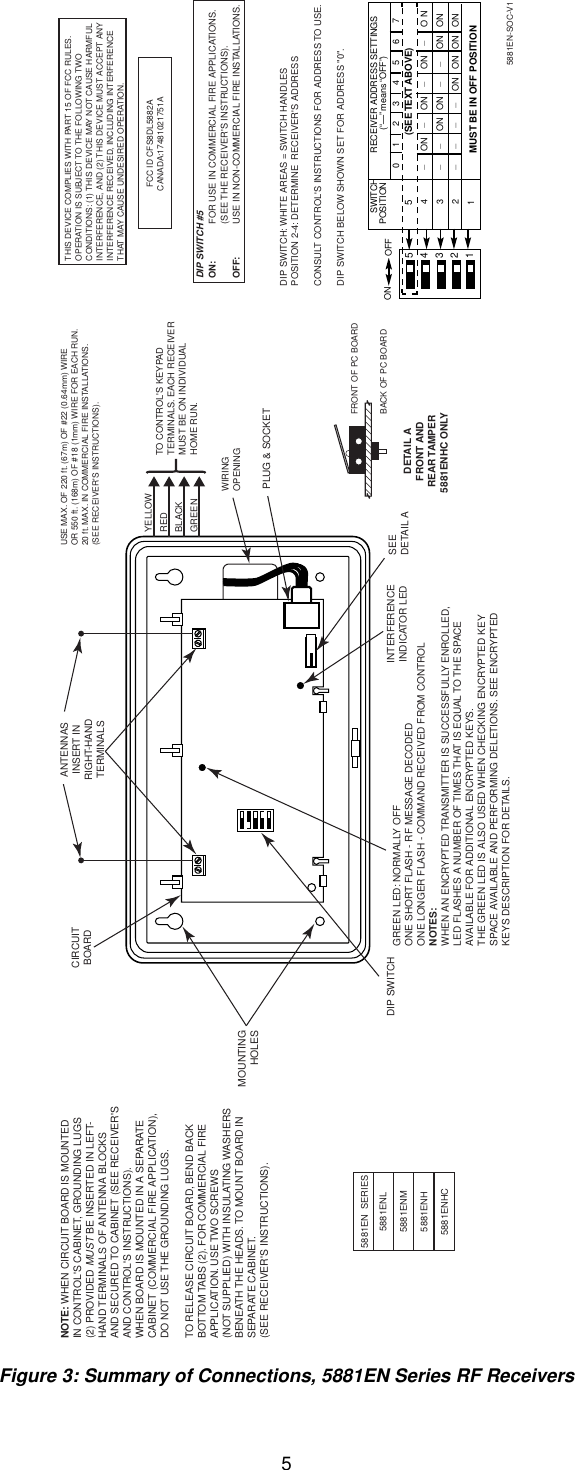
Ademco 8DL5882-4 Remote Control Security RX User Manual N7635 3V3 II

Honeywell International Inc. Remote Control Security RX N7635 3V3 II

ii with FCC information

 1  N7635-3V3 1/01 5881EN Series RF Receiver INSTALLATION AND SETUP GUIDE INTRODUCTION The 5881EN series of RF receivers is designed for use with control panels that support an RF receiver connection via the keypad terminals. The receiver recognizes alarm, status, and keypad control messages from wireless transmitters operating at 345MHz.  One or two individually identified receivers can be employed, depending on the control used. Connection of multiple receivers to a control can provide redundant coverage or extend coverage in large areas. These receivers feature a Spatial Diversity System that virtually eliminates the possibility of "nulls" and "dead spots" within the coverage area. The 5881EN series of receivers use ADEMCO’s new Signal-Sentry™ technology, and can be used in commercial fire installations. Additionally, the 5881ENHC receiver contains front and back tamper that permits its use in commercial burglary installations. UL •  In commercial fire applications, the receiver can only be used with control panels that are approved for use in Commercial Fire Installations. When the 5881EN is used in commercial fire applications, DIP switch 5 must be in the ON position. • In commercial burglary applications, the 5881ENHC can only be used with control panels that are approved for use in Commercial Burglary Installations. •  In commercial fire applications, a keypad must be connected to Keypad Port 2 in the control. The keypad must be mounted on the control or within 3 feet of the control with the wiring encased in conduit. Each receiver supports the number of zones shown below. 5881ENL Up to 8 zones 5881ENM Up to 16 zones 5881ENH *See below 5881ENHC *See below * The number of zones that the 5881ENH receiver can support depends on the control with which it is used. See the control panel’s instructions for specific details. If a receiver is connected to a system in which more than the permitted number of wireless zones have been programmed, a "SET UP ERROR" message (on alpha keypads) or an "E4 or “E8”" message (on fixed-word keypads) will be displayed on the system's keypad, and none of the zones will be protected. The instruction manual that accompanies the control includes recommendations regarding receiver and transmitter locations, the types of wireless zones that can be programmed (e.g., ENTRY/EXIT, PERIMETER, INTERIOR, etc.) and the procedure for programming the receivers. These receivers should not be installed in an area subject to environmental extremes of below freezing (such as an unheated warehouse) or extremely high temperatures (such as an attic). INSTALLATION With some controls, a receiver may be mounted directly inside the control's cabinet (receiver circuit board only, without its plastic housing) instead of remotely (in its own housing). In both cases, avoid mounting the receiver antennas against a metal surface. NOTE: You may only mount the 5881ENHC its own plastic housing. If you attempt to mount the 5881ENHC in the control’s cabinet, the receiver constantly reports a tamper condition. 1.  Remove the receiver's cover by inserting and twisting a screwdriver blade in the slot at the center of the cover's lower edge. 2. If the receiver is to be mounted within the control's cabinet (refer to Figure 1): a. Remove the receiver's circuit board from its base by bending back the two flexible plastic tabs that hold the board's lower edge. b. In the control's cabinet, unfasten and move the control circuit board downward (if already installed). c.  Hang two mounting clips (provided with the receiver) on the raised cabinet tabs, as shown in Detail B of Figure 1. d.  Insert the top of the receiver board between the rows of slots at the top of the cabinet, as shown in Detail A. e. Position the base of the receiver board onto the mounting clips and secure to the cabinet with the supplied screws. See Detail B. f.  Hang two mounting clips (supplied with the control board), on the raised cabinet tabs as shown in Detail C in Figure 1. g.  Insert the top of the control board into the slots of the mounting clips secured in step e above. h. Position the lower end of the control board into place on the mounting clips and secure both to the cabinet with the two supplied screws.  i. Insert both grounding lugs (supplied with the receiver) through the top of the cabinet into the left-hand terminals of the antenna blocks (located on the upper edge of the receiver board), and secure them to the cabinet with the screws provided, as shown in Detail D.
 2 MOUNTINGCLIPCABINETDETAIL DANTENNA AND GROUNDING LUG INSTALLATIONANTENNAMOUNT(2 PLACES)ANTENNA(2)SCREW(2)MOUNTINGCLIPCONTROLCIRCUITBOARDBOARDSUPPORTINGSLOTSHOLES FOR ANTENNASAND GROUNDING LUGSRECEIVER CIRCUIT BOARD(See Detail D)++++RCVR BRDDETAIL ASIDE VIEWOF BOARD SUPPORTING SLOTSDETAIL BSIDE VIEWOF MOUNTINGCLIPDETAIL CSIDE VIEWOF MOUNTINGCLIPGROUNDINGLUG(2)pcb_RF_mount-V0CIRCUIT BOARDCABINET Figure 1: Installing the Receiver Board in the Control’s Cabinet j.  Insert the receiver’s antennas through the top of the cabinet, into the blocks’ right-hand terminals, and tighten the screws. k. Affix the receiver's Summary of Connections label to the inside of the control's cabinet door. l.  Discard the receiver's unused plastic cover and base. 3. If the receiver is to be located remotely from the control in its own plastic enclosure (not in a cabinet):   You will not need the circuit board mounting clips, grounding lugs and screws included with the receiver. a.  If concealed wiring is to be used, route it through the rectangular opening at the rear of the base before mounting. For surface wiring entry, a thin breakaway area is provided along the base's right edge. b. Mount the receiver in the selected location. For greatest security, use all four mounting holes (two keyslot holes and two round holes) provided in the plastic base.  c.  If installing a 5881ENHC, install a flat-head screw (supplied) in the case tamper tab as shown in Figure 2. When the receiver is pried from the wall, the tamper tab will break off and remain on the wall. This will activate a tamper switch in the receiver and cause generation of a tamper signal. Note that this signal will also be generated when the receiver’s front cover is removed. d. Affix the receiver's Summary of Connections label to the inside of the housing cover. 5881ENHC-001-V0SCREW Figure 2: Tamper Protection 4.  Setting the DIP switches (All Receivers):  a. Set the receiver's DIP switch (#2 through #4) to identify the receiver's address (refer to the DIP switch chart in Figure 3).
 3 b.  Verify that DIP switch #1 is in the OFF position. c.  Set DIP switch #5 according to the following chart. DIP SWITCH #5 For . . .  Set to . . . Commercial Fire Applications  ON Non-commercial Fire Applications  OFF NOTES: •  If multiple receivers are used on one control, DIP switch #5 must be set to the same position on all receivers. • DIP switch #5 reduces sensitivity during supervision message reception. For commercial fire applications, DIP switch #5 must be in the ON position. 5.  Insert the wiring plug (with 4 flying leads) into the mating socket on the receiver (see Figure 3 for socket location). Connect the 4 wires to the control's corresponding keypad terminals (see “Interface Wiring” in the SPECIFICATIONS section). 6. Install the antennas in the right-hand terminals of the two terminal blocks at the upper edge of the circuit board, one into each block’s right-hand terminal, and tighten the screws to secure them.   Caution: Avoid mounting the receiver antennas against a metal surface. 7.  Proceed with any programming of the control that may be necessary for RF operation, and the installation of the system's wireless transmitters, as described in the control's installation and setup guide and the transmitter's installation instructions.  NOTES: •  The receiver can support up to 16 encrypted wireless transmitters (keys). The total quantity of wireless keys (encrypted and unencrypted) that can be used is determined by the control panel. •  Wireless key buttons must be enrolled to zones in the control panel via zone programming first. If the wireless key is to be used for arming and disarming the VISTA-40 and up, a user number must then be assigned to the wireless key via user programming. If it is not done in this order, you will be unable to respond successfully to the RF button zone number prompt in user programming. •  If more than one receiver is being used and you are using encrypted wireless keys, we recommend that you (a) enter the GO/NO GO mode, (b) disconnect one receiver, (c) enroll all encrypted keys into the connected receiver, (d) reconnect the disconnected receiver, (e) exit the GO/NO GO mode, and then (f) repeat (a) through (e) for the receiver that was disconnected.  •  The RED LED located on the receiver's circuit board should be used as an indicator of strong local radio frequency interference. If this LED is continuously illuminated, the receiver should be relocated. •  After a successful enrollment of an encrypted key, the GREEN LED blinks the number of spaces that are free for additional encrypted key enrollment. 8.  Replace the receiver's cover. ENCRYPTED KEYS The receiver can support up to 16 encrypted wireless transmitters (keys) at one time. If the number on the receiver microprocessor is WAK 4406-4 or higher, the receiver provides you with the capability to check space available and/or delete encrypted keys using the procedures below. The GREEN LED located on the receiver's circuit board may be used to determine how many more encrypted keys may be enrolled into the receiver. This LED is also used to indicate when encrypted keys may be deleted. To determine how many more encrypted keys may be enrolled and/or to delete enrolled encrypted keys: 1. Remove power from the receiver and set DIP switch 1 to the ON position. 2.  Apply power to the receiver and watch the GREEN LED. You will see one of the following indications: a. The GREEN LED blinks the number of spaces that are free for additional encrypted key enrollment and then goes to constantly ON. b. The GREEN LED is constantly ON, indicating the receiver is full. c. The GREEN LED is OFF, indicating no encrypted keys are enrolled. 3. If you do not want to delete any enrolled encrypted keys, advance to step 4. If you want to delete enrolled encrypted keys, wait until the GREEN LED is constantly ON in step 2 a. or 2 b. above and then: a. Record the positions of DIP switches 1 through 5. b. Set DIP switches 1 through 5 to the opposite positions of their current settings and wait a few moments. c. Set DIP switches 1 through 5 back to their original positions as recorded in step a. All enrolled encrypted keys will be deleted. 4. Place DIP switch 1 back into the OFF position to return to normal receiver operation.
 4 SPECIFICATIONS Dimensions:   7-3/8" W x 4-3/8" (10-7/8” w/antennas) H x 1-7/16" D   188mm W x 112mm H (277mm w/antennas) x 37mm D Input Voltage:   12VDC (from control’s keypad terminals) Current:  60mA (typical) Operating Temperature:  0-50°C Interface Wiring:   RED  12VDC input (+) Aux. Power   GREEN:  Data Out to Control   YELLOW:  Data In from Control  BLACK:  Ground (–) Range:   200ft (60m) nominal indoors from wireless transmitters (the actual range to be determined with the security system in the Test mode).    TO THE INSTALLER Regular maintenance and inspection (at least annually) by the installer and frequent testing by the user are vital to continuous satisfactory operation of any alarm system.  The installer should assume the responsibility of developing and offering a regular maintenance program to the user, as well as acquainting the user with the proper operation and limitations of the alarm system and its component parts. Recommendations must be included for a specific program of frequent testing (at least weekly) to insure the system's operation at all times.
 5  GREEN LED: NORMALLY OFFONE SHORT FLASH - RF MESSAGE DECODEDONE LONGER FLASH - COMMAND RECEIVED FROM CONTROLNOTES:WHEN AN ENCRYPTED TRANSMITTER IS SUCCESSFULLY ENROLLED,LED FLASHES A NUMBER OF TIMES THAT IS EQUAL TO THE SPACE AVAILABLE FOR ADDITIONAL ENCRYPTED KEYS.THE GREEN LED IS ALSO USED WHEN CHECKING ENCRYPTED KEY SPACE AVAILABLE AND PERFORMING DELETIONS. SEE ENCRYPTEDKEYS DESCRIPTION FOR DETAILS.NOTE: WHEN CIRCUIT BOARD IS MOUNTEDIN CONTROL'S CABINET, GROUNDING LUGS(2) PROVIDED MUST BE INSERTED IN LEFT-HAND TERMINALS OF ANTENNA BLOCKS AND SECURED TO CABINET (SEE RECEIVER'S AND CONTROL'S INSTRUCTIONS).WHEN BOARD IS MOUNTED IN A SEPARATECABINET (COMMERCIAL FIRE APPLICATION),DO NOT USE THE GROUNDING LUGS.TO RELEASE CIRCUIT BOARD, BEND BACKBOTTOM TABS (2). FOR COMMERCIAL FIREAPPLICATION. USE TWO SCREWS(NOT SUPPLIED) WITH INSULATING WASHERSBENEATH THE HEADS. TO MOUNT BOARD INSEPARATE CABINET.(SEE RECEIVER'S INSTRUCTIONS).MOUNTINGHOLESCIRCUITBOARDINTERFERENCEINDICATOR LEDPLUG & SOCKETWIRINGOPENINGYELLOWREDBLACKGREENFCC ID CFS8DL5882ACANADA:17481021751AUSE MAX. OF 220 ft. (67m) OF #22 (0.64mm) WIREOR 550 ft. (168m) OF #18 (1mm) WIRE FOR EACH RUN. 20 ft. MAX. IN COMMERCIAL FIRE INSTALLATIONS.(SEE RECEIVER'S INSTRUCTIONS).TO CONTROL'S KEYPADTERMINALS. EACH RECEIVERMUST BE ON INDIVIDUALHOME RUN.THIS DEVICE COMPLIES WITH PART 15 OF FCC RULES.OPERATION IS SUBJECT TO THE FOLLOWING TWOCONDITIONS: (1) THIS DEVICE MAY NOT CAUSE HARMFULINTERFERENCE, AND (2) THIS DEVICE MUST ACCEPT ANYINTERFERENCE RECEIVED, INCLUDING INTERFERENCETHAT MAY CAUSE UNDESIRED OPERATION.DIP SWITCH #5ON:  FOR USE IN COMMERCIAL FIRE APPLICATIONS.(SEE THE RECEIVER'S INSTRUCTIONS).OFF: USE IN NON-COMMERCIAL FIRE INSTALLATIONS.SWITCH RECEIVER ADDRESS SETTINGSPOSITION (“—” means “OFF”)012345675    (SEE TEXT ABOVE)4—ON —ON —ON —ON3——ON ON ——ON ON2————ON ON ON ON154321ON OFFMUST BE IN OFF POSITIONDETAIL AFRONT ANDREAR TAMPER5881ENHC ONLY SEEDETAIL A5881EN  SERIES5881ENL5881ENM5881ENHC5881ENHDIP SWITCH: WHITE AREAS = SWITCH HANDLESPOSITION 2-4: DETERMINE  RECEIVER'S ADDRESSCONSULT CONTROL'S INSTRUCTIONS FOR ADDRESS TO USE.DIP SWITCH BELOW SHOWN SET FOR ADDRESS "0".BACK OF PC BOARDFRONT OF PC BOARDANTENNASINSERT INRIGHT-HANDTERMINALSDIP SWITCH5881EN-SOC-V1  Figure 3: Summary of Connections, 5881EN Series RF Receivers
 6 FEDERAL COMMUNICATIONS COMMISSION (FCC) STATEMENT This equipment has been tested to FCC requirements and has been found acceptable for use. The FCC requires the following statement for your information: This equipment generates and uses radio frequency energy and if not installed and used properly, that is, in strict accordance with the manufacturer's instructions, may cause interference to radio and television reception. It has been type tested and found to comply with the limits for a Class B computing device in accordance with the specifications in Part 15 of FCC Rules, which are designed to provide reasonable protection against such interference in a residential installation. However, there is no guarantee that interference will not occur in a particular installation. If this equipment does cause interference to radio or television reception, which can be determined by turning the equipment off and on, the user is encouraged to try to correct the interference by one or more of the following measures: •  If using an indoor antenna, have a quality outdoor antenna installed. •  Reorient the receiving antenna until interference is reduced or eliminated.  •  Move the radio or television receiver away from the receiver/control. •  Move the antenna leads away from any wire runs to the receiver/control. •  Plug the receiver/control into a different outlet so that it and the radio or television receiver are on different branch circuits. If necessary, the user should consult the dealer or an experienced radio/television technician for additional suggestions. The user or installer may find the following booklet prepared by the Federal Communications Commission helpful: "Interference Handbook" This booklet is available under Stock No. 004-000-00450-7 from the U.S. Government Printing Office, Washington, DC 20402. The user shall not make any changes or modifications to the equipment unless authorized by the Installation and Setup Guide or User Guide. Unauthorized changes or modifications could void the user's authority to operate the equipment.  WARNING THE LIMITATIONS OF THIS WIRELESS ALARM SYSTEM  While this System is an advanced wireless security system, it does not offer guaranteed protection against burglary, fire or other emergency. Any alarm system, whether commercial or residential, is subject to compromise or failure to warn for a variety of reasons. For example: •  Intruders may gain access through unprotected openings or have the technical sophistication to bypass an alarm sensor or disconnect an alarm warning device. •  Intrusion detectors (e.g., passive infrared detectors), smoke detectors, and many other sensing devices will not work without power. Battery-operated devices will not work without batteries, with dead batteries, or if the batteries are not put in properly. Devices powered solely by AC will not work if their AC power supply is cut off for any reason, however briefly.  •  Signals sent by wireless transmitters may be blocked or reflected by metal before they reach the alarm receiver. Even if the signal path has been recently checked during a weekly test, blockage can occur if a metal object is moved into the path. •  A user may not be able to reach a panic or emergency button quickly enough. •  While smoke detectors have played a key role in reducing residential fire deaths in the United States, they may not activate or provide early warning for a variety of reasons in as many as 35% of all fires, according to data published by the Federal Emergency Management Agency. Some of the reasons smoke detectors used in conjunction with this System may not work are as follows. Smoke detectors may have been improperly installed and positioned. Smoke detectors may not sense fires that start where smoke cannot reach the detectors, such as in chimneys, in walls, or roofs, or on the other side of closed doors. Smoke detectors also may not sense a fire on another level of a residence or building. A second floor detector, for example, may not sense a first floor or basement fire. Finally, smoke detectors have sensing limitations. No smoke detector can sense every kind of fire every time. In general, detectors may not always warn about fires caused by carelessness and safety hazards like smoking in bed, violent explosions, escaping gas, improper storage of flammable materials, overloaded electrical circuits, children playing with matches, or arson. Depending on the nature of the fire and/or location of the smoke detectors, the detector, even if it operates as anticipated, may not provide sufficient warning to allow all occupants to escape in time to prevent injury or death. •  Passive Infrared Motion Detectors can only detect intrusion within the designed ranges as diagrammed in their installation manual. Passive Infrared Detectors do not provide volumetric area protection. They do create multiple beams of protection, and intrusion can only be detected in unobstructed areas covered by those beams. They cannot detect motion or intrusion that takes place behind walls, ceilings, floors, closed doors, glass partitions, glass doors, or windows. Mechanical tampering, masking, painting or spraying of any material on the mirrors, windows or any part of the optical system can reduce their detection ability. Passive Infrared Detectors sense changes in temperature; however, as the ambient temperature of the protected area approaches the temperature range of 90° to 105°F (32° to 40°C), the detection performance can decrease. •  Alarm warning devices such as sirens, bells or horns may not alert people or wake up sleepers if they are located on the other side of closed or partly open doors. If warning devices are located on a different level of the residence from the bedrooms, then they are less likely to waken or alert people inside the bedrooms. Even persons who are awake may not hear the warning if the alarm is muffled by noise from a stereo, radio, air conditioner or other appliance, or by passing traffic. Finally, alarm warning devices, however loud, may not warn hearing-impaired people. •  Telephone lines needed to transmit alarm signals from a premises to a central monitoring station may be out of service or temporarily out of service. Telephone lines are also subject to compromise by sophisticated intruders. •  Even if the system responds to the emergency as intended, however, occupants may have insufficient time to protect themselves from the emergency situation. In the case of a monitored alarm system, authorities may not respond appropriately. •  This equipment, like other electrical devices, is subject to component failure. Even though this equipment is designed to last as long as 20 years, the electronic components could fail at any time. The most common cause of an alarm system not functioning when an intrusion or fire occurs is inadequate maintenance. This alarm system should be tested weekly to make sure all sensors and transmitters are working properly. The security console (and remote keypad) should be tested as well. This system's wireless transmitters are designed to provide long battery life under normal operating conditions. Longevity of batteries may be as much as 7 years, depending on the environment, usage, and the specific wireless device being used. External factors such as humidity, high or low temperatures, as well as large swings in temperature, may all reduce the actual battery life in a given installation. This wireless system, however, can identify a true low battery situation, thus allowing time to arrange a change of battery to maintain protection for that given point within the system. Installing an alarm system may make the owner eligible for a lower insurance rate, but an alarm system is not a substitute for insurance. Homeowners, property owners and renters should continue to act prudently in protecting themselves and continue to insure their lives and property. We continue to develop new and improved protection devices. Users of alarm systems owe it to themselves and their loved ones to learn about these developments.
 7          ADEMCO LIMITED WARRANTY Alarm Device Manufacturing Company, a Division of Pittway Corporation, and its divisions, subsidiaries and affiliates ("Seller"), 165 Eileen Way, Syosset, New York 11791, warrants its products to be in conformance with its own plans and specifications and to be free from defects in materials and workmanship under normal use and service for 24 months from the date stamp control on the product or, for products not having an ADEMCO date stamp, for 12 months from date of original purchase unless the installation instructions or catalog sets forth a shorter period, in which case the shorter period shall apply. Seller's obligation shall be limited to repairing or replacing, at its option, free of charge for materials or labor, any product which is proved not in compliance with Seller's specifications or proves defective in materials or workmanship under normal use and service. Seller shall have no obligation under this Limited Warranty or otherwise if the product is altered or improperly repaired or serviced by anyone other than ADEMCO factory service. For warranty service, return product transportation prepaid, to ADEMCO Factory Service, 165 Eileen Way, Syosset, New York 11791. THERE ARE NO WARRANTIES, EXPRESS OR IMPLIED, OF MERCHANTABILITY, OR FITNESS FOR A PARTICULAR PURPOSE OR OTHERWISE, WHICH EXTEND BEYOND THE DESCRIPTION ON THE FACE HEREOF. IN NO CASE SHALL SELLER BE LIABLE TO ANYONE FOR ANY CONSEQUENTIAL OR INCIDENTAL DAMAGES FOR BREACH OF THIS OR ANY OTHER WARRANTY, EXPRESS OR IMPLIED, OR UPON ANY OTHER BASIS OF LIABILITY WHATSOEVER, EVEN IF THE LOSS OR DAMAGE IS CAUSED BY THE SELLER'S OWN NEGLIGENCE OR FAULT. Seller does not represent that the products it sells may not be compromised or circumvented; that the products will prevent any personal injury or property loss by burglary, robbery, fire or otherwise; or that the products will in all cases provide adequate warning or protection. Customer understands that a properly installed and maintained alarm may only reduce the risk of a burglary, robbery, fire or other events occurring without providing an alarm, but it is not insurance or a guarantee that such will not occur or that there will be no personal injury or property loss as a result. CONSEQUENTLY, SELLER SHALL HAVE NO LIABILITY FOR ANY PERSONAL INJURY, PROPERTY DAMAGE OR OTHER LOSS BASED ON A CLAIM THE PRODUCT FAILED TO GIVE WARNING. HOWEVER, IF SELLER IS HELD LIABLE, WHETHER DIRECTLY OR INDIRECTLY, FOR ANY LOSS OR DAMAGE ARISING UNDER THIS LIMITED WARRANTY OR OTHERWISE, REGARDLESS OF CAUSE OR ORIGIN, SELLER'S MAXIMUM LIABILITY SHALL NOT IN ANY CASE EXCEED THE PURCHASE PRICE OF THE PRODUCT, WHICH SHALL BE THE COMPLETE AND EXCLUSIVE REMEDY AGAINST SELLER. This warranty replaces any previous warranties and is the only warranty made by Seller on this product. No increase or alteration, written or verbal, of the obligations of this Limited Warranty is authorized.
¬19lN7635-3V3 1/01                                                                    165 Eileen Way, Syosset, New York 11791 Copyright © 2001 PITTWAY CORPORATION

Navigation menu