Ademco 8DL5883-2 remote security transceiver User Manual K3791 iibx
Honeywell International Inc. remote security transceiver K3791 iibx
Ademco >
ii with FCC statment
K3791 (bx) 6/6/01
®
,167$//$7,21$1'6(783*8,'(
INTRODUCTION
The 5883 series RF Transceiver Module contains an RF receiver and a
transmitter. It is intended for use with ADEMCO’s 5800 series RF
transmitters, including bi-directional wireless units (e.g. 5827BD,
5804BD), and the 5800RL Wireless Relay Module (see Fig. 1).
The 5883 receives alarm, status, and control messages from 5800
transmitters, and passes these messages to the control panel via
wired connections. The control then responds accordingly (arm/disarm
the system, initiate an alarm, etc.). The 5883 also transmits system
status and other conditions to 5804BD or 5827BD bi-directional units
(if used). The 5883 can emulate the functions of a 5800TM module,
and can control the relays on the 5800RL Wireless Relay Module.
The 5883 features a Spatial Diversity system that virtually eliminates
the possibility of "Nulls" and "Dead Spots" within the coverage area. It
also incorporates ADEMCO’s new high-security encryption technology
(UL-864 and RF Jam Detect).
If more than the permitted number of wireless zones are programmed,
a "SET UP ERROR" message (on alpha keypads) or an "E4 or “E8”"
message (on fixed-word keypads) will be displayed on the system's
keypad, and none of the zones will be protected.
The 5883 models support the number of zones shown below.
5883M Up to 16 zones
5883H Depends on the control with which it is used. See
the control panel’s instructions for specific
details.
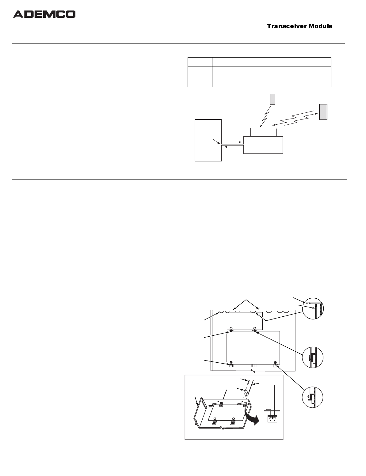
5883
TRANSCEIVER
CONTROL
PANEL
*
5800 SERIES
WIRELESS TRANSMITTERS
*
CONTROL MUST BE CAPABLE OF
SUPPORTING A 5800 RF SYSTEM
2-WAY
WIRELESS KEYPAD
(e.g., 5827BD, 5804BD)
OR
5800RL 2-WAY RELAY
MODULE
KEYPAD
TERMINALS
ON CONTROL
BOARD
2-WAY
TRANSMISSION
DATA IN TO
CONTROL
DATA OUT
TO 5883
Figure 1. Block Diagram
MOUNT THE MODULE OR PC BOARD
The 5883 can be mounted remotely, or, with some controls, can be mounted inside the control's cabinet. When mounting, make sure the
antennas do not touch any metal surfaces.
First, Check for RF Interference: Before mounting permanently,
use the red RF Interference LED (see figure 3) to check for strong
local radio frequency interference at the intended mounting location.
If this LED is continuously lit, the 5883 module should be relocated.
Removing the Cover
Remove the 5883's cover by inserting and twisting a screwdriver blade
in the slot at the center of the cover's lower edge.
Replace the cover when installation is complete if unit is not
mounted within a cabinet.
Mounting inside the control's cabinet (refer to Fig. 2):
1. Remove the 5883’s circuit board from its base by bending back the
two flexible plastic tabs that hold the board's lower edge. Discard
the 5883's unused plastic cover and base.
2. In the control's cabinet, unfasten and move the control circuit board
downward (if already installed).
3. Hang two short (black) mounting clips (provided) on the raised
cabinet tabs in the cabinet, as shown in Detail B of Figure 2.
4. Insert the top of the 5883’s board into the supporting slots at the
top of the cabinet (Detail A). Swing the bottom of the board into the
two short (black) mounting clips installed in step 3, and secure it to
the cabinet with the accompanying screws. See Detail B.
5. Insert the top of the control’s board into the slot in the black clips
holding the lower edge of the 5883 board (see Detail B); position two
long (red) clips at the lower edge of the board (see Detail C).
6. Swing the lower edge of the control board into place, and secure
with two additional screws.
7. Insert the grounding lugs (provided) through the top of the cabinet
and into the left-hand terminals of the antenna blocks (at the
upper edge of the 5883's circuit board). Secure it to the cabinet with
the two screws provided. See Detail D.
8. Insert the 5883’s two antennas through the two openings in the
top of the cabinet, one into each block’s right-hand terminal, and
tighten the screws to secure them.
9. Affix the 5883's Summary of Connections label to the inside of the
control's cabinet door.
Mounting the 5883 remotely
NOTE: If mounting the 5883 in its own enclosure, the supplied PCB
mounting clips, grounding lugs, and screws are not needed.
1. For concealed wiring, route wires through the rectangular opening
at the rear of the base before mounting. For surface wiring entry,
a thin breakaway area is provided along the base's right edge.
2. Mount the module in the selected location. For greatest security,
use all four mounting holes (two keyslot holes and two round
holes) in the plastic base.
3. Install each antenna in the respective right-hand terminal of the
two terminal blocks at the upper edge of the 5883’s circuit board,
and tighten the screws to secure them.
4. Affix the 5883's Summary of Connections label to the inside of the
housing cover.
MOUNTING
CLIP
CABINET
DETAIL D
ANTENNA AND GROUNDING LUG INSTALLATION
ANTENNA
MOUNT
(2 PLACES)
ANTENNA
(2)
SCREW
(2)
MOUNTING
CLIP
CONTROL
CIRCUIT
BOARD
BOARD
SUPPORTING
SLOTS
HOLES FOR ANTENNAS
AND GROUNDING LUGS
RECEIVER CIRCUIT BOARD
(See Detail D)
++
++
RCVR BRD
DETAIL A
SIDE VIEW
OF BOARD
SUPPORTING SLOTS
DETAIL B
SIDE VIEW
OF MOUNTING
CLIP
DETAIL C
SIDE VIEW
OF MOUNTING
CLIP
GROUNDING
LUG
(2)
pcb_RF_mount-V0
CIRCUIT BOARD
CABINET
Figure 2. Installing the 5883 Board in the Control’s Cabinet
(Check the control’s Installation Instructions for applicability)
GO TO PAGE 3 FOR THE
FCC PART 15 STATMENT
AND FCC ID NUMBER
AND THE IC ID NUMBER
– 2 –
Mounting for Commercial Fire Applications (in separate cabinet)
For Commercial Fire applications, the 5883 module must be mounted
in a separate cabinet (N4868V4–BE), using the ADEMCO Cam Lock
(N6277), and Retainer Clip (N6277–1). Refer to the control’s
instructions for installing the Cam Lock and Retainer Clip.
The cabinet containing the module must be located no more than 20 feet
from the alarm control cabinet (maximum wire run length 20 feet), with
no intervening walls or barriers.
1. Remove the PC board by bending back the two flexible plastic tabs
that hold the board's lower edge. Discard the 5883’s unused plastic
cover and base.
2. Insert the top of the board into the supporting slots at the top of
the cabinet (see Detail A, Figure 2).
Secure the bottom of the board with the 2 screws removed in step
1 above, using an insulating washer (supplied) between the head of
each mounting screw and the PC board.
3. Affix the 5883's Summary of Connections label to the inside of the
cabinet door.
IMPORTANT: If mounting the 5883 in a separate cabinet in a
Commercial Fire installation, do not use the antenna grounding lugs.
SET THE DIP SWITCHES
Use the DIP switches to set the 5883’s device address, to activate
Commercial Fire usage (if applicable), to enable the built-in
transmitter, and to check or delete encrypted keys.
Addresses: The 5883 Transceiver has two device addresses: one for
the receiver (addresses 1-7) and one for the transmitter (addresses
27-30, similar to the 5800TM device addresses; see notes 5 and 6
below)). First, select a pair of addresses from the table below,
making sure that neither address is currently being used in the
alarm system, then use DIP switches 2-4 to set the address pair. The
addresses should then be programmed in the control. Do not program
the transmitter’s address in the control if the 5883 is not being used
with 5800TM compatible devices, such as the 5804BD or 5827BD
DIP Switch Functions
Sw. Function
1 Check/deactivate high-security keys (see High-Security Keys paragraph)
Device Address Settings
Transmitter: 28 29 30 27 28 29 30
Receiver: Non-
Addr. 123456 7
2 OFF OFF OFF OFF ON ON ON ON
3 OFF OFF ON ON OFF OFF ON ON
4 OFF ON OFF ON OFF ON OFF ON
5Commercial/Non-commercial Fire Installation:
ON = commercial fire system (see Notes for Commercial Fire Apps.)
OFF = non-commercial fire system
6 ON = enable transmitter (if using 5800TM compatible devices)
NOTE: If using more than one 5883 in a system, enable the
transmitter in only one 5883.
OFF = disable transmitter
7 Not used; leave in OFF position
8 Used when removing RF keypads (see Removing RF Keypads
paragraph); otherwise leave OFF
NOTES:
•If multiple 5883 Transceivers are used on one control, DIP switch
5 must be set to the same position on all receivers.
•DIP switch 5 reduces sensitivity during supervision message
reception. For Commercial Fire applications (see note box), you
must set DIP switch 5 to the ON position.
•DIP switches 2–4 select both an RF receiver and an RF
transmitter device address.
•When used with 5800TM compatible devices such as the 5800RL,
5804BD, or the 5827BD, the selected transmitter device address
must be enabled as a “keypad” in the control and DIP switch 6
must be set to “ON.”
•If the 5883 is not being used with 5800TM compatible devices,
such as the 5804BD or 5827BD, the RF transmitter address should
be ignored and DIP switch 6 should be set to OFF.
•If programming the control to supervise the 5883, program only
the receiver address for supervision. Do not program the
transmitter address for supervision.
Notes for Commercial Fire Applications:
•DIP switch 5 must be in the ON position.
•All other system components, including the control, must be
approved for use in Commercial Fire applications.
•When the 5883 is not used in a Commercial Fire application,
switch 5 must be placed in the OFF position.
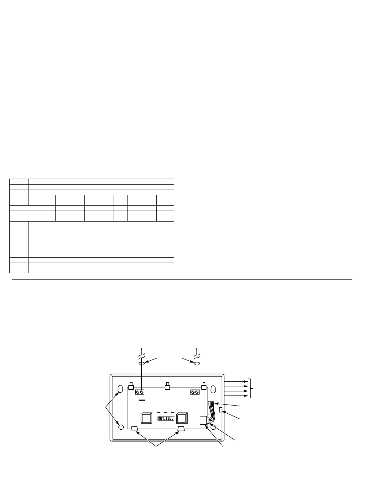
CONNECT THE WIRING FROM THE CONTROL
1. Insert the wiring plug (with 4 flying leads) into the mating socket
on the 5883 (see Figure 3 for socket location).
2. Connect the 4 wires to the control's corresponding remote keypad
connection points as follows:
RED 12VDC input (+) Aux Power
GREEN: Data to Control (control’s data IN)
YELLOW: Data from Control (control’s data OUT)
BLACK: Ground (–)
LED FUNCTIONS (refer to Figure 3)
Red RF Interference LED: Lit Indicates local RF interference.
Green LED: Flickering indicates reception of messages (decoded
and/or non-decoded).
Yellow LED: Occasional blinks occur under normal operation.
Red LED: Blinks indicate available space for high security keys;
Steady ON indicates ready to deactivate high security
keys or remove wireless (RF) keypads.
See High Security Keys and Wireless Keypads
section below for more information.
RF INTERFERENCE
RED INDICATOR
REDYELGRN
DIP SWITCH
ON
OFF 23456781
5883 CIRCUIT BOARD
MOUNTING
HOLES
(4)
ANTENNAS
(INSERT IN
RIGHT-HAND
TERMINALS)
YELLOW
RED
BLACK
GREEN
WIRING
OPENING
KNOCKOUT AREA
FOR SURFACE WIRING
TO
CONTROL'S
REMOTE
KEYPAD
CONNECTION
POINTS
TO RELEASE CIRCUIT BOARD,
BEND BACK TABS SOCKET
PLUG
5883-002-V0
Figure 3. 5883 Transceiver

– 3 –
PROGRAM THE CONTROL FOR RF OPERATION
Proceed with any control panel programming that may be necessary for RF operation and the installation of the system's wireless transmitters,
as described in the control's installation instructions. In addition, note the following:
•Enable the appropriate control data field for RF usage.
•Enroll the wireless keypad address(es), if used (see instructions
provided with keypad).
•Wireless key buttons must first be enrolled in the control panel via
zone programming, and, where applicable, assigned to a user
number. Enroll each wireless key in the 5883 by pressing the
appropriate buttons according to the instructions provided with
the key.
•Upon the successful enrollment of an encrypted key, the red LED
blinks the number of available spaces remaining for additional
encrypted key enrollment (see Checking Available Space For High
Security Keys paragraph).
•If more than one receiver is being used and you are using
encrypted wireless keys, we recommend that you:
a. Enter the GO/NO GO mode.
b. Disconnect one receiver.
c. Enroll all encrypted keys into the connected receiver.
d. Reconnect the disconnected receiver.
e. Exit the GO/NO GO mode.
f. Repeat steps a-e for the receiver that was disconnected.
HIGH SECURITY KEYS & WIRELESS KEYPADS
Depending on the control panel used, the 5883 can support up to 16 high-security (encrypted) wireless keys and up to 16 wireless keypads (e.g.,
5839). The following paragraphs describe how to:
• Check available space for high-security keys
• How to deactivate all keys
• How to remove all wireless keypads.
See the Control’s instructions and the appropriate device instructions for procedures on enrolling high security keys and wireless keypads.
Checking Available Space for High Security Keys
The RED LED (above the DIP switch) shows (by blinking) how many
high-security keys may be enrolled into the transceiver.
1. Remove power from the transceiver and set DIP switches:
DIP 1 = ON
DIP 8 = OFF
2. Apply power and observe one of the following RED LED indications:
a. Blinks, indicating the number of available spaces for additional
high-security key enrollment, and then lights steady ON.
b. Immediate Steady ON (no blinks), indicating that high-
security key enrollment is full.
c. Off, indicating that no encrypted keys are enrolled.
3. Set DIP switch 1 back to the OFF position to return to normal
receiver operation (leave DIP 8 in OFF position).
Deactivating High-Security keys
This procedure deactivates all enrolled high-security keys and is
required only if previously enrolled high-security keys are being
replaced and there is not enough available space left for them in the
receiver. Once this procedure is performed, all desired high-security
keys must be re-enrolled to activate high-security operation.
1. Perform steps 1 and 2 in Checking Available Space procedure
above.
2. Wait until the RED LED lights steady ON then:
a. Record the positions of DIP switches 1 through 8.
b. Set DIP switches 1 through 8 to the opposite positions of their
current settings and wait a few moments.
c. Set DIP switches 1 through 8 back to their original positions as
recorded in step a. All enrolled high-security keys will be
deactivated.
3. Set DIP switch 1 back to the OFF position to return to normal
receiver operation (leave DIP 8 in OFF position).
Removing All Wireless Keypads
This procedure removes all wireless keypad from the transceiver.
1. Remove power from the transceiver and set DIP switches:
DIP 1 = OFF
DIP 8 = ON
2. Apply power and observe the RED LED lights steady ON, then:
a. Record the positions of DIP switches 1 through 8.
b. Set DIP switches 1 through 8 to the opposite positions of their
current settings and wait a few moments.
c. Set DIP switches 1 through 8 back to their original positions as
recorded in step a. All enrolled wireless keypads will be
removed from the transceiver.
3. Set DIP switch 8 back to the OFF position to return to normal
receiver operation (leave DIP 1 in OFF position).
NOTE: If unsure that correct RF keypad (5839) addresses are
enabled in the receiver, you should perform the RF keypad delete
procedure, then enable RF keypad addresses as described in the
instructions included with the RF keypad. Otherwise, erroneous ecp
device “check” messages may occur.
FCC ID: CFS8DL5883-2
This device complies with Part 15 of the FCC Rules. Operation is
subject to the following two conditions: (1) This device may not
cause harmful interference, and (2) this device must accept any
interference received, including interference that may cause
undesired operation.
IC: 573F-58832
This Class B digital apparatus complies with Canadian ICES-003.
Cet Appareil numérique de la classe B est conforme à la norme
NMB-003 du Canada.
SPECIFICATIONS
Dimensions:
7-3/8" W x 4-3/8" (10-7/8” w/antennas) H x 1-7/16" D
188mm W x 112mm H (277mm w/antennas) x 37mm D
Input Voltage: 12VDC (from control’s remote keypad terminals)
Current: 80mA typical
Range: 200ft (60m) nominal indoors from wireless devices (actual
range is determined with the control in TEST mode)
TO THE INSTALLER
Regular maintenance and inspection (at least annually) by the
installer and frequent testing by the user are vital to continuous
satisfactory operation of any alarm system.
The installer should assume the responsibility of developing and
offering a regular maintenance program to the user, as well as
acquainting the user with the proper operation and limitations of
the alarm system and its component parts. Recommendations
must be included for a specific program of frequent testing (at
least weekly) to insure the system's operation at all times.

WARNING
THE LIMITATIONS OF THIS WIRELESS ALARM SYSTEM
While this System is an advanced wireless security system, it does not offer guaranteed protection against burglary, fire or other emergency. Any alarm system, whether
commercial or residential, is subject to compromise or failure to warn for a variety of reasons. For example:
• Intruders may gain access through unprotected openings or have the technical sophistication to bypass an alarm sensor or disconnect an alarm warning device.
• Intrusion detectors (e.g., passive infrared detectors), smoke detectors, and many other sensing devices will not work without power. Battery-operated devices will not work
without batteries, with dead batteries, or if the batteries are not put in properly. Devices powered solely by AC will not work if their AC power supply is cut off for any reason,
however briefly.
• Signals sent by wireless transmitters may be blocked or reflected by metal before they reach the alarm receiver. Even if the signal path has been recently checked during a
weekly test, blockage can occur if a metal object is moved into the path.
• A user may not be able to reach a panic or emergency button quickly enough.
• While smoke detectors have played a key role in reducing residential fire deaths in the United States, they may not activate or provide early warning for a variety of reasons
in as many as 35% of all fires, according to data published by the Federal Emergency Management Agency. Some of the reasons smoke detectors used in conjunction with
this System may not work are as follows. Smoke detectors may have been improperly installed and positioned. Smoke detectors may not sense fires that start where smoke
cannot reach the detectors, such as in chimneys, in walls, or roofs, or on the other side of closed doors. Smoke detectors also may not sense a fire on another level of a
residence or building. A second floor detector, for example, may not sense a first floor or basement fire. Finally, smoke detectors have sensing limitations. No smoke detector
can sense every kind of fire every time. In general, detectors may not always warn about fires caused by carelessness and safety hazards like smoking in bed, violent
explosions, escaping gas, improper storage of flammable materials, overloaded electrical circuits, children playing with matches, or arson. Depending on the nature of the fire
and/or location of the smoke detectors, the detector, even if it operates as anticipated, may not provide sufficient warning to allow all occupants to escape in time to prevent
injury or death.
• Passive Infrared Motion Detectors can only detect intrusion within the designed ranges as diagrammed in their installation manual. Passive Infrared Detectors do not provide
volumetric area protection. They do create multiple beams of protection, and intrusion can only be detected in unobstructed areas covered by those beams. They cannot
detect motion or intrusion that takes place behind walls, ceilings, floors, closed doors, glass partitions, glass doors, or windows. Mechanical tampering, masking, painting or
spraying of any material on the mirrors, windows or any part of the optical system can reduce their detection ability. Passive Infrared Detectors sense changes in
temperature; however, as the ambient temperature of the protected area approaches the temperature range of 90° to 105°F (32° to 40°C), the detection performance can
decrease.
• Alarm warning devices such as sirens, bells or horns may not alert people or wake up sleepers if they are located on the other side of closed or partly open doors. If warning
devices are located on a different level of the residence from the bedrooms, then they are less likely to waken or alert people inside the bedrooms. Even persons who are
awake may not hear the warning if the alarm is muffled by noise from a stereo, radio, air conditioner or other appliance, or by passing traffic. Finally, alarm warning devices,
however loud, may not warn hearing-impaired people.
• Telephone lines needed to transmit alarm signals from a premises to a central monitoring station may be out of service or temporarily out of service. Telephone lines are also
subject to compromise by sophisticated intruders.
• Even if the system responds to the emergency as intended, however, occupants may have insufficient time to protect themselves from the emergency situation. In the case
of a monitored alarm system, authorities may not respond appropriately.
• This equipment, like other electrical devices, is subject to component failure. Even though this equipment is designed to last as long as 10 years, the electronic components
could fail at any time.
The most common cause of an alarm system not functioning when an intrusion or fire occurs is inadequate maintenance. This alarm system should be tested weekly to make
sure all sensors and transmitters are working properly. The security console (and remote keypad) should be tested as well.
This system's wireless transmitters are designed to provide long battery life under normal operating conditions. Longevity of batteries may be as much as 7 years, depending on
the environment, usage, and the specific wireless device being used. External factors such as humidity, high or low temperatures, as well as large swings in temperature, may
all reduce the actual battery life in a given installation. This wireless system, however, can identify a true low battery situation, thus allowing time to arrange a change of battery
to maintain protection for that given point within the system.
Installing an alarm system may make the owner eligible for a lower insurance rate, but an alarm system is not a substitute for insurance. Homeowners, property owners and
renters should continue to act prudently in protecting themselves and continue to insure their lives and property.
We continue to develop new and improved protection devices. Users of alarm systems owe it to themselves and their loved ones to learn about these developments.
LIMITED WARRANTY
Alarm Device Manufacturing Company, a Division of Pittway Corporation, and its divisions, subsidiaries and affiliates ("Seller"), 165 Eileen Way,
Syosset, New York 11791, warrants its products to be in conformance with its own plans and specifications and to be free from defects in materials and
workmanship under normal use and service for 24 months from the date stamp control on the product or, for products not having an Ademco date
stamp, for 12 months from date of original purchase unless the installation instructions or catalog sets forth a shorter period, in which case the shorter
period shall apply. Seller's obligation shall be limited to repairing or replacing, at its option, free of charge for materials or labor, any product which is
proved not in compliance with Seller's specifications or proves defective in materials or workmanship under normal use and service. Seller shall have
no obligation under this Limited Warranty or otherwise if the product is altered or improperly repaired or serviced by anyone other than Ademco factory
service. For warranty service, return product transportation prepaid, to ADEMCO Factory Service, 170 Michael Drive, Syosset, New York 11791.
THERE ARE NO WARRANTIES, EXPRESS OR IMPLIED, OF MERCHANTABILITY, OR FITNESS FOR A PARTICULAR PURPOSE OR
OTHERWISE, WHICH EXTEND BEYOND THE DESCRIPTION ON THE FACE HEREOF. IN NO CASE SHALL SELLER BE LIABLE TO ANYONE
FOR ANY CONSEQUENTIAL OR INCIDENTAL DAMAGES FOR BREACH OF THIS OR ANY OTHER WARRANTY, EXPRESS OR IMPLIED, OR
UPON ANY OTHER BASIS OF LIABILITY WHATSOEVER, EVEN IF THE LOSS OR DAMAGE IS CAUSED BY THE SELLER'S OWN NEGLIGENCE
OR FAULT.
Seller does not represent that the products it sells may not be compromised or circumvented; that the products will prevent any personal injury or
property loss by burglary, robbery, fire or otherwise; or that the products will in all cases provide adequate warning or protection. Customer understands
that a properly installed and maintained alarm may only reduce the risk of a burglary, robbery, fire or other events occurring without providing an alarm,
but it is not insurance or a guarantee that such will not occur or that there will be no personal injury or property loss as a result. CONSEQUENTLY,
SELLER SHALL HAVE NO LIABILITY FOR ANY PERSONAL INJURY, PROPERTY DAMAGE OR OTHER LOSS BASED ON A CLAIM THE
PRODUCT FAILED TO GIVE WARNING. HOWEVER, IF SELLER IS HELD LIABLE, WHETHER DIRECTLY OR INDIRECTLY, FOR ANY LOSS OR
DAMAGE ARISING UNDER THIS LIMITED WARRANTY OR OTHERWISE, REGARDLESS OF CAUSE OR ORIGIN, SELLER'S MAXIMUM
LIABILITY SHALL NOT IN ANY CASE EXCEED THE PURCHASE PRICE OF THE PRODUCT, WHICH SHALL BE THE COMPLETE AND
EXCLUSIVE REMEDY AGAINST SELLER. This warranty replaces any previous warranties and is the only warranty made by Seller on this product. No
increase or alteration, written or verbal, of the obligations of this Limited Warranty is authorized.
165 Eileen Way, Syosset, New York 11791
Copyright © 2001 PITTWAY CORPORATION
¬.l
K3791 5/01