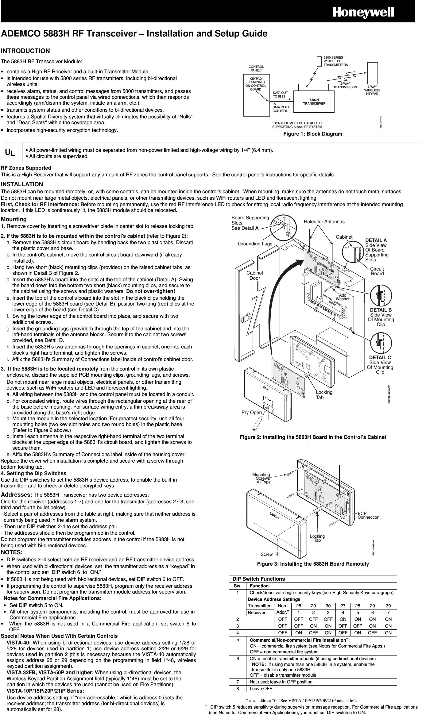
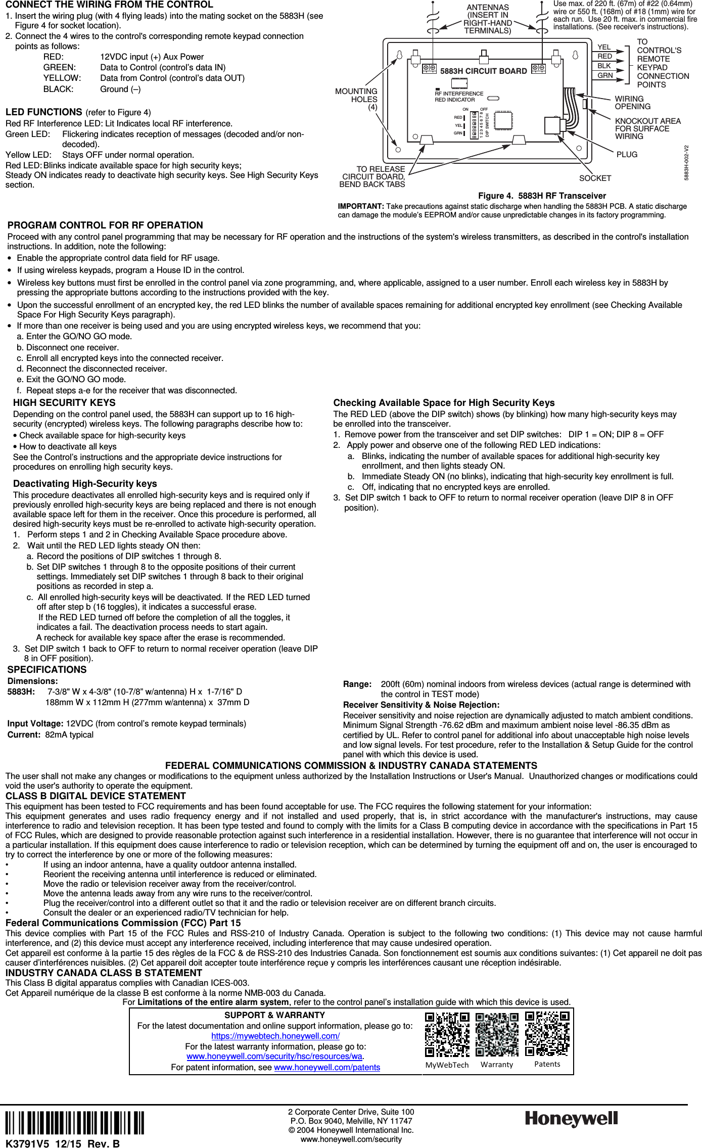
Ademco 8DL5883-3 RF TRANSCEIVER FOR USE WITH 5800 RF TRANSMITTERS User Manual K3791V5 B 5883 ii

Honeywell International Inc. RF TRANSCEIVER FOR USE WITH 5800 RF TRANSMITTERS K3791V5 B 5883 ii

User Manual

    ADEMCO 5883H RF Transceiver – Installation and Setup Guide    INTRODUCTION The 5883H RF Transceiver Module: •  contains a High RF Receiver and a built-in Transmitter Module, •  is intended for use with 5800 series RF transmitters, including bi-directional wireless units, •  receives alarm, status, and control messages from 5800 transmitters, and passes these messages to the control panel via wired connections, which then responds accordingly (arm/disarm the system, initiate an alarm, etc.), •  transmits system status and other conditions to bi-directional devices, •  features a Spatial Diversity system that virtually eliminates the possibility of "Nulls" and "Dead Spots" within the coverage area, •  incorporates high-security encryption technology.   KEYPADTERMINALSON CONTROLBOARDCONTROLPANEL*DATA OUTTO 5883DATA IN TOCONTROL*CONTROL MUST BE CAPABLE OFSUPPORTING A 5800 RF SYSTEM5883HTRANSCEIVER5800 SERIESWIRELESSTRANSMITTERS2-WAYWIRELESSKEYPAD5883-003-V02-WAYTRANSMISSION Figure 1: Block Diagram UL • All power-limited wiring must be separated from non-power limited and high-voltage wiring by 1/4" (6.4 mm). • All circuits are supervised.  RF Zones Supported This is a High Receiver that will support any amount of RF zones the control panel supports.  See the control panel’s instructions for specific details.  INSTALLATION The 5883H can be mounted remotely, or, with some controls, can be mounted inside the control's cabinet.  When mounting, make sure the antennas do not touch metal surfaces.  Do not mount near large metal objects, electrical panels, or other transmitting devices, such as WiFi routers and LED and florescent lighting. First, Check for RF Interference: Before mounting permanently, use the red RF Interference LED to check for strong local radio frequency interference at the intended mounting location. If this LED is continuously lit, the 5883H module should be relocated.   Mounting 1. Remove cover by inserting a screwdriver blade in center slot to release locking tab.  2. If the 5883H is to be mounted within the control's cabinet (refer to Figure 2): a. Remove the 5883H’s circuit board by bending back the two plastic tabs. Discard the plastic cover and base. b. In the control's cabinet, move the control circuit board downward (if already installed). c. Hang two short (black) mounting clips (provided) on the raised cabinet tabs, as shown in Detail B of Figure 2. d. Insert the 5883H’s board into the slots at the top of the cabinet (Detail A). Swing the board down into the bottom two short (black) mounting clips, and secure to the cabinet using the screws and plastic washers. Do not over-tighten! e. Insert the top of the control’s board into the slot in the black clips holding the lower edge of the 5883H board (see Detail B); position two long (red) clips at the lower edge of the board (see Detail C). f.  Swing the lower edge of the control board into place, and secure with two additional screws.  g. Insert the grounding lugs (provided) through the top of the cabinet and into the left-hand terminals of the antenna blocks. Secure it to the cabinet two screws provided, see Detail D.  h. Insert the 5883H’s two antennas through the openings in cabinet, one into each block’s right-hand terminal, and tighten the screws.  i.  Affix the 5883H's Summary of Connections label inside of control's cabinet door. 3.  If the 5883H is to be located remotely from the control in its own plastic enclosure, discard the supplied PCB mounting clips, grounding lugs, and screws. Do not mount near large metal objects, electrical panels, or other transmitting devices, such as WiFi routers and LED and florescent lighting. a. All wiring between the 5883H and the control panel must be located in a conduit. b.  For concealed wiring, route wires through the rectangular opening at the rear of the base before mounting. For surface wiring entry, a thin breakaway area is provided along the base's right edge. c. Mount the module in the selected location. For greatest security, use all four mounting holes (two key slot holes and two round holes) in the plastic base. (Refer to Figure 2 above.) d. Install each antenna in the respective right-hand terminal of the two terminal blocks at the upper edge of the 5883H’s circuit board, and tighten the screws to secure them. e. Affix the 5883H's Summary of Connections label inside of the housing cover. Replace the cover when installation is complete and secure with a screw through bottom locking tab. 4. Setting the Dip Switches Use the DIP switches to set the 5883H’s device address, to enable the built-in transmitter, and to check or delete encrypted keys.  Addresses: The 5883H Transceiver has two device addresses:  One for the receiver (addresses 1-7) and one for the transmitter (addresses 27-3; see third and fourth bullet below).  - Select a pair of addresses from the table at right, making sure that neither address is currently being used in the alarm system, - Then use DIP switches 2-4 to set the address pair.  - The addresses should then be programmed in the control.  Do not program the transmitter modules address in the control if the 5883H is not being used with bi-directional devices. NOTES: •  DIP switches 2–4 select both an RF receiver and an RF transmitter device address. •  When used with bi-directional devices, set  the transmitter address as a “keypad” in the control and set  DIP switch 6  to “ON.” •  If 5883H is not being used with bi-directional devices, set DIP switch 6 to OFF. •  If programming the control to supervise 5883H, program only the receiver address for supervision. Do not program the transmitter module address for supervision. Notes for Commercial Fire Applications:  •  Set DIP switch 5 to ON.   •  All other system components, including the control, must be approved for use in Commercial Fire applications.  •  When  the  5883H  is  not  used  in  a  Commercial  Fire  application,  set  switch  5  to OFF. Special Notes When Used With Certain Controls  VISTA-40: When  using bi-directional devices,  use  device  address setting  1/28 or 5/28  for  devices  used  in  partition  1;  use  device  address  setting  2/29  or  6/29  for devices used in partition 2 (this is necessary because the VISTA-40 automatically assigns  address  28  or  29  depending  on  the  programming  in  field  1*48,  wireless keypad partition assignment). VISTA 32FB, VISTA-50P and higher: When using bi-directional devices, the Wireless Keypad Partition Assignment field (typically 1*48) must be set to the partition in which the devices are used (cannot be used on Fire Partitions).  VISTA-10P/15P/20P/21iP Series:    Use device address setting of “non-addressable,” which is address 0 (sets the receiver address; the transmitter address (for bi-directional devices) is automatically set for 28). Pry OpenRECEIVERCIRCUITBOARDBoard SupportingSlots.See Detail ADETAIL BSide ViewOf MountingClipDETAIL CSide ViewOf MountingClipDETAIL ASide ViewOf Board SupportingSlotsCircuitBoardCabinetCONTROL CIRCUITBOARD5883HAddWasherLockingTab5883H-004-V0Holes for AntennasCabinetDoorGrounding Lugs Figure 2: Installing the 5883H Board in the Control’s Cabinet  Screw5883HLockingTab5883H-005-V0MountingScrews4 (Typ)ECPConnection Figure 3: Installing the 5883H Board Remotely                                           * also address “0.” See VISTA-10P/15P/20P/21iP note at left.  †  DIP switch 5 reduces sensitivity during supervision message reception. For Commercial Fire applications (see Notes for Commercial Fire Applications), you must set DIP switch 5 to ON. DIP Switch Functions Sw.  Function 1  Check/deactivate high-security keys (see High-Security Keys paragraph)    Device Address Settings   Transmitter: Non- Addr.* 28  29  30  27  28  29  30   Receiver:  1  2  3  4  5  6  7 2    OFF  OFF  OFF  OFF  ON  ON  ON  ON 3    OFF  OFF  ON  ON  OFF  OFF  ON  ON 4    OFF  ON  OFF  ON  OFF  ON  OFF  ON 5  Commercial/Non-commercial Fire Installation†: ON = commercial fire system (see Notes for Commercial Fire Apps.) OFF = non-commercial fire system  6  ON =  enable transmitter module (if using bi-directional devices)  NOTE:  If using more than one 5883H in a system, enable the transmitter in only one 5883H. OFF = disable transmitter module 7  Not used; leave in OFF position 8  Leave OFF
   CONNECT THE WIRING FROM THE CONTROL 1. Insert the wiring plug (with 4 flying leads) into the mating socket on the 5883H (see Figure 4 for socket location).  2. Connect the 4 wires to the control's corresponding remote keypad connection points as follows:   RED:  12VDC input (+) Aux Power   GREEN:  Data to Control (control’s data IN)   YELLOW:  Data from Control (control’s data OUT)   BLACK:  Ground (–)  LED FUNCTIONS (refer to Figure 4) Red RF Interference LED: Lit Indicates local RF interference.  Green LED:  Flickering indicates reception of messages (decoded and/or non-decoded). Yellow LED:  Stays OFF under normal operation. Red LED: Blinks indicate available space for high security keys;  Steady ON indicates ready to deactivate high security keys. See High Security Keys  section.   5883H CIRCUIT BOARDMOUNTINGHOLES(4)ANTENNAS(INSERT INRIGHT-HANDTERMINALS)YELREDBLKGRNWIRINGOPENINGKNOCKOUT AREAFOR SURFACEWIRINGTOCONTROL'SREMOTEKEYPADCONNECTIONPOINTSTO RELEASECIRCUIT BOARD,BEND BACK TABS SOCKETPLUG5883H-002-V22 3 4 5 6 7 81ON OFFRF INTERFERENCERED INDICATORREDYELGRNDIP SWITCHUse max. of 220 ft. (67m) of #22 (0.64mm)wire or 550 ft. (168m) of #18 (1mm) wire foreach run.  Use 20 ft. max. in commercial fireinstallations. (See receiver's instructions). Figure 4.  5883H RF Transceiver IMPORTANT: Take precautions against static discharge when handling the 5883H PCB. A static discharge can damage the module’s EEPROM and/or cause unpredictable changes in its factory programming. PROGRAM CONTROL FOR RF OPERATION Proceed with any control panel programming that may be necessary for RF operation and the instructions of the system's wireless transmitters, as described in the control's installation instructions. In addition, note the following: •  Enable the appropriate control data field for RF usage. •  If using wireless keypads, program a House ID in the control. •  Wireless key buttons must first be enrolled in the control panel via zone programming, and, where applicable, assigned to a user number. Enroll each wireless key in 5883H by pressing the appropriate buttons according to the instructions provided with the key. •  Upon the successful enrollment of an encrypted key, the red LED blinks the number of available spaces remaining for additional encrypted key enrollment (see Checking Available Space For High Security Keys paragraph).  •  If more than one receiver is being used and you are using encrypted wireless keys, we recommend that you:   a. Enter the GO/NO GO mode.   b. Disconnect one receiver.   c. Enroll all encrypted keys into the connected receiver.   d. Reconnect the disconnected receiver.   e. Exit the GO/NO GO mode.   f.  Repeat steps a-e for the receiver that was disconnected. HIGH SECURITY KEYS  Depending on the control panel used, the 5883H can support up to 16 high-security (encrypted) wireless keys. The following paragraphs describe how to: • Check available space for high-security keys • How to deactivate all keys  See the Control’s instructions and the appropriate device instructions for procedures on enrolling high security keys. Deactivating High-Security keys This procedure deactivates all enrolled high-security keys and is required only if previously enrolled high-security keys are being replaced and there is not enough available space left for them in the receiver. Once this procedure is performed, all desired high-security keys must be re-enrolled to activate high-security operation. 1.  Perform steps 1 and 2 in Checking Available Space procedure above.  2.  Wait until the RED LED lights steady ON then: a. Record the positions of DIP switches 1 through 8. b. Set DIP switches 1 through 8 to the opposite positions of their current settings. Immediately set DIP switches 1 through 8 back to their original positions as recorded in step a. c.  All enrolled high-security keys will be deactivated. If the RED LED turned off after step b (16 toggles), it indicates a successful erase.      If the RED LED turned off before the completion of all the toggles, it indicates a fail. The deactivation process needs to start again.      A recheck for available key space after the erase is recommended. 3.  Set DIP switch 1 back to OFF to return to normal receiver operation (leave DIP 8 in OFF position). Checking Available Space for High Security Keys  The RED LED (above the DIP switch) shows (by blinking) how many high-security keys may be enrolled into the transceiver. 1.  Remove power from the transceiver and set DIP switches:   DIP 1 = ON; DIP 8 = OFF 2.  Apply power and observe one of the following RED LED indications:   a.  Blinks, indicating the number of available spaces for additional high-security key enrollment, and then lights steady ON.   b.  Immediate Steady ON (no blinks), indicating that high-security key enrollment is full.   c.  Off, indicating that no encrypted keys are enrolled. 3.  Set DIP switch 1 back to OFF to return to normal receiver operation (leave DIP 8 in OFF position).   SPECIFICATIONS Dimensions:  5883H:   7-3/8" W x 4-3/8" (10-7/8” w/antenna) H x  1-7/16" D   188mm W x 112mm H (277mm w/antenna) x  37mm D  Input Voltage: 12VDC (from control’s remote keypad terminals) Current:  82mA typical    Range:   200ft (60m) nominal indoors from wireless devices (actual range is determined with the control in TEST mode) Receiver Sensitivity & Noise Rejection:  Receiver sensitivity and noise rejection are dynamically adjusted to match ambient conditions. Minimum Signal Strength -76.62 dBm and maximum ambient noise level -86.35 dBm as certified by UL. Refer to control panel for additional info about unacceptable high noise levels and low signal levels. For test procedure, refer to the Installation & Setup Guide for the control panel with which this device is used.   FEDERAL COMMUNICATIONS COMMISSION & INDUSTRY CANADA STATEMENTS The user shall not make any changes or modifications to the equipment unless authorized by the Installation Instructions or User's Manual.  Unauthorized changes or modifications could void the user's authority to operate the equipment. CLASS B DIGITAL DEVICE STATEMENT This equipment has been tested to FCC requirements and has been found acceptable for use. The FCC requires the following statement for your information: This  equipment  generates  and  uses  radio  frequency  energy  and  if  not  installed  and  used  properly,  that  is,  in  strict  accordance  with  the  manufacturer's  instructions,  may  cause interference to radio and television reception. It has been type tested and found to comply with the limits for a Class B computing device in accordance with the specifications in Part 15 of FCC Rules, which are designed to provide reasonable protection against such interference in a residential installation. However, there is no guarantee that interference will not occur in a particular installation. If this equipment does cause interference to radio or television reception, which can be determined by turning the equipment off and on, the user is encouraged to try to correct the interference by one or more of the following measures: •  If using an indoor antenna, have a quality outdoor antenna installed. •  Reorient the receiving antenna until interference is reduced or eliminated.  •  Move the radio or television receiver away from the receiver/control. •  Move the antenna leads away from any wire runs to the receiver/control. •  Plug the receiver/control into a different outlet so that it and the radio or television receiver are on different branch circuits.  •  Consult the dealer or an experienced radio/TV technician for help. Federal Communications Commission (FCC) Part 15 This  device  complies  with  Part  15  of  the  FCC  Rules  and  RSS-210  of  Industry  Canada.  Operation  is  subject  to  the  following  two  conditions:  (1)  This  device  may  not  cause  harmful interference, and (2) this device must accept any interference received, including interference that may cause undesired operation. Cet appareil est conforme à la partie 15 des règles de la FCC & de RSS-210 des Industries Canada. Son fonctionnement est soumis aux conditions suivantes: (1) Cet appareil ne doit pas causer d’interférences nuisibles. (2) Cet appareil doit accepter toute interférence reçue y compris les interférences causant une réception indésirable. INDUSTRY CANADA CLASS B STATEMENT This Class B digital apparatus complies with Canadian ICES-003. Cet Appareil numérique de la classe B est conforme à la norme NMB-003 du Canada. For Limitations of the entire alarm system, refer to the control panel’s installation guide with which this device is used. SUPPORT & WARRANTY For the latest documentation and online support information, please go to: https://mywebtech.honeywell.com/  For the latest warranty information, please go to: www.honeywell.com/security/hsc/resources/wa.  For patent information, see www.honeywell.com/patents  MyWebTech  Warranty  Patents  ÊK3791V5vŠ K3791V5  12/15  Rev. B 2 Corporate Center Drive, Suite 100 P.O. Box 9040, Melville, NY 11747 © 2004 Honeywell International Inc. www.honeywell.com/security

Navigation menu