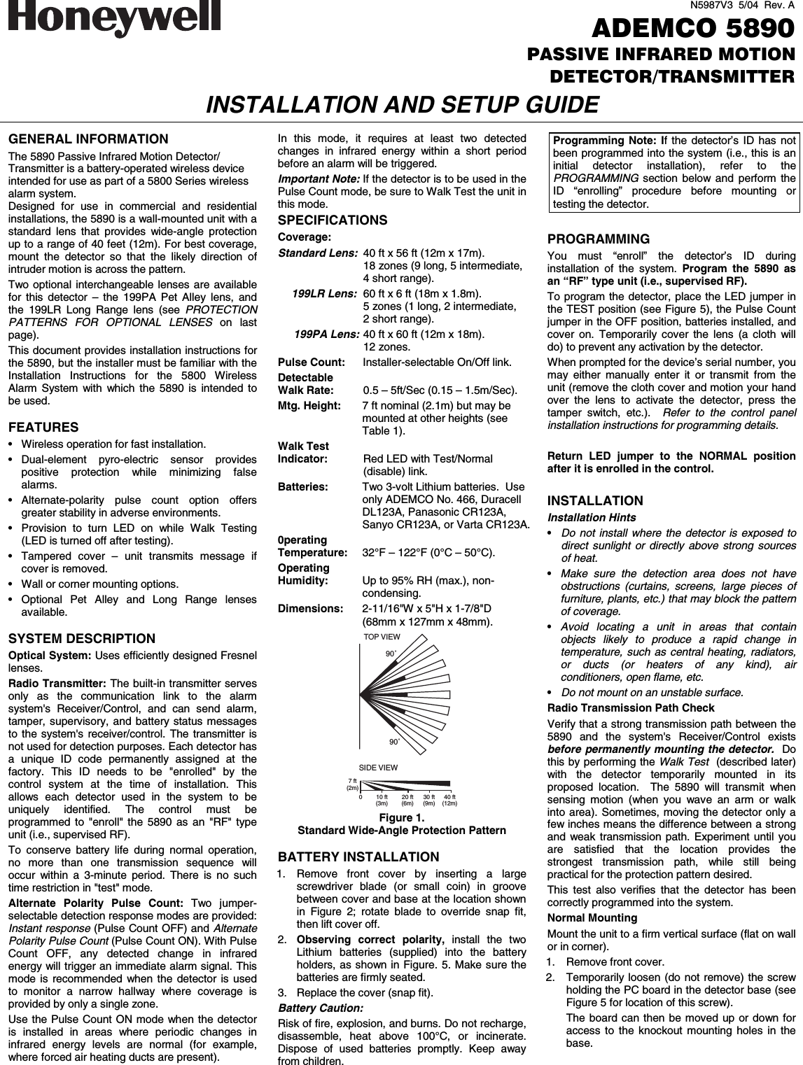
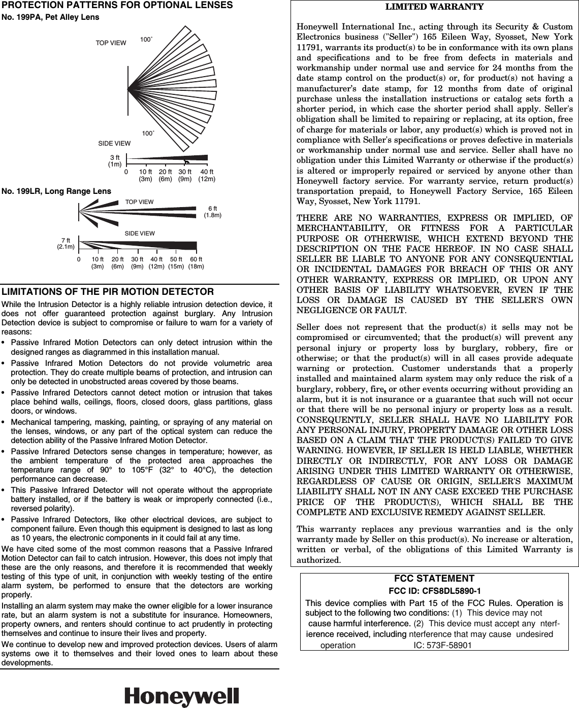
Ademco 8DL5890-1 motion detector transmitter User Manual N5987V3 Rev A

Honeywell International Inc. motion detector transmitter N5987V3 Rev A

II with part 15 statment and fcc id number

N5987V3  5/04  Rev. A ADEMCO 5890 PASSIVE INFRARED MOTION DETECTOR/TRANSMITTER INSTALLATION AND SETUP GUIDE  GENERAL INFORMATION The 5890 Passive Infrared Motion Detector/ Transmitter is a battery-operated wireless device intended for use as part of a 5800 Series wireless alarm system.  Designed for use in commercial and residential installations, the 5890 is a wall-mounted unit with a standard lens that provides wide-angle protection up to a range of 40 feet (12m). For best coverage, mount the detector so that the likely direction of intruder motion is across the pattern.  Two optional interchangeable lenses are available for this detector – the 199PA Pet Alley lens, and the 199LR Long Range lens (see PROTECTION PATTERNS FOR OPTIONAL LENSES on last page).  This document provides installation instructions for the 5890, but the installer must be familiar with the Installation Instructions for the 5800 Wireless Alarm System with which the 5890 is intended to be used.  FEATURES •  Wireless operation for fast installation. • Dual-element pyro-electric sensor provides positive protection while minimizing false alarms. • Alternate-polarity pulse count option offers greater stability in adverse environments. •  Provision to turn LED on while Walk Testing (LED is turned off after testing). • Tampered cover – unit transmits message if cover is removed. •  Wall or corner mounting options. • Optional Pet Alley and Long Range lenses available.  SYSTEM DESCRIPTION Optical System: Uses efficiently designed Fresnel lenses. Radio Transmitter: The built-in transmitter serves only as the communication link to the alarm system's Receiver/Control, and can send alarm, tamper, supervisory, and battery status messages to the system's receiver/control. The transmitter is not used for detection purposes. Each detector has a unique ID code permanently assigned at the factory. This ID needs to be "enrolled" by the control system at the time of installation. This allows each detector used in the system to be uniquely identified. The control must be programmed to "enroll" the 5890 as an "RF" type unit (i.e., supervised RF).  To conserve battery life during normal operation, no more than one transmission sequence will occur within a 3-minute period. There is no such time restriction in "test" mode. Alternate Polarity Pulse Count: Two jumper-selectable detection response modes are provided: Instant response (Pulse Count OFF) and Alternate Polarity Pulse Count (Pulse Count ON). With Pulse Count OFF, any detected change in infrared energy will trigger an immediate alarm signal. This mode is recommended when the detector is used to monitor a narrow hallway where coverage is provided by only a single zone. Use the Pulse Count ON mode when the detector is installed in areas where periodic changes in infrared energy levels are normal (for example, where forced air heating ducts are present).  In this mode, it requires at least two detected changes in infrared energy within a short period before an alarm will be triggered. Important Note: If the detector is to be used in the Pulse Count mode, be sure to Walk Test the unit in this mode. SPECIFICATIONS Coverage: Standard Lens:  40 ft x 56 ft (12m x 17m).    18 zones (9 long, 5 intermediate,   4 short range).  199LR Lens:  60 ft x 6 ft (18m x 1.8m).      5 zones (1 long, 2 intermediate,    2 short range).  199PA Lens: 40 ft x 60 ft (12m x 18m).    12 zones. Pulse Count:  Installer-selectable On/Off link. Detectable  Walk Rate:  0.5 – 5ft/Sec (0.15 – 1.5m/Sec). Mtg. Height:  7 ft nominal (2.1m) but may be mounted at other heights (see Table 1). Walk Test Indicator:  Red LED with Test/Normal     (disable) link. Batteries:  Two 3-volt Lithium batteries.  Use only ADEMCO No. 466, Duracell DL123A, Panasonic CR123A, Sanyo CR123A, or Varta CR123A. 0perating Temperature:  32°F – 122°F (0°C – 50°C). Operating Humidity:  Up to 95% RH (max.), non- condensing. Dimensions:  2-11/16"W x 5"H x 1-7/8"D (68mm x 127mm x 48mm). TOP VIEWSIDE VIEW90˚90˚0 10 ft 20 ft 30 ft 40 ft(3m) (6m) (9m) (12m)7 ft(2m) Figure 1. Standard Wide-Angle Protection Pattern  BATTERY INSTALLATION 1.  Remove front cover by inserting a large screwdriver blade (or small coin) in groove between cover and base at the location shown in Figure 2; rotate blade to override snap fit, then lift cover off. 2.  Observing correct polarity, install the two Lithium batteries (supplied) into the battery holders, as shown in Figure. 5. Make sure the batteries are firmly seated. 3.  Replace the cover (snap fit). Battery Caution: Risk of fire, explosion, and burns. Do not recharge, disassemble, heat above 100°C, or incinerate. Dispose of used batteries promptly. Keep away from children. Programming Note: If the detector’s ID has not been programmed into the system (i.e., this is an initial detector installation), refer to the PROGRAMMING section below and perform the ID “enrolling” procedure before mounting or testing the detector.  PROGRAMMING You must “enroll” the detector’s ID during installation of the system. Program the 5890 as an “RF” type unit (i.e., supervised RF).   To program the detector, place the LED jumper in the TEST position (see Figure 5), the Pulse Count jumper in the OFF position, batteries installed, and cover on. Temporarily cover the lens (a cloth will do) to prevent any activation by the detector.  When prompted for the device’s serial number, you may either manually enter it or transmit from the unit (remove the cloth cover and motion your hand over the lens to activate the detector, press the tamper switch, etc.).  Refer to the control panel installation instructions for programming details.   Return LED jumper to the NORMAL position after it is enrolled in the control.  INSTALLATION Installation Hints • Do not install where the detector is exposed to direct sunlight or directly above strong sources of heat. • Make sure the detection area does not have obstructions (curtains, screens, large pieces of furniture, plants, etc.) that may block the pattern of coverage. • Avoid locating a unit in areas that contain objects likely to produce a rapid change in temperature, such as central heating, radiators, or ducts (or heaters of any kind), air conditioners, open flame, etc. • Do not mount on an unstable surface. Radio Transmission Path Check Verify that a strong transmission path between the 5890 and the system's Receiver/Control exists before permanently mounting the detector.  Do this by performing the Walk Test  (described later) with the detector temporarily mounted in its proposed location.  The 5890 will transmit when sensing motion (when you wave an arm or walk into area). Sometimes, moving the detector only a few inches means the difference between a strong and weak transmission path. Experiment until you are satisfied that the location provides the strongest transmission path, while still being practical for the protection pattern desired.   This test also verifies that the detector has been correctly programmed into the system.  Normal Mounting Mount the unit to a firm vertical surface (flat on wall or in corner). 1.  Remove front cover. 2.  Temporarily loosen (do not remove) the screw holding the PC board in the detector base (see Figure 5 for location of this screw).    The board can then be moved up or down for access to the knockout mounting holes in the base.
 PROTECTION PATTERNS FOR OPTIONAL LENSES No. 199PA, Pet Alley Lens TOP VIEW 100˚100˚SIDE VIEW0 10 ft 20 ft 30 ft 40 ft(3m) (6m) (9m) (12m)3 ft(1m) No. 199LR, Long Range Lens SIDE VIEW0 10 ft 20 ft 30 ft 40 ft 50 ft 60 ft(3m) (6m) (9m) (12m) (15m) (18m)7 ft(2.1m)TOP VIEW6 ft(1.8m)  LIMITATIONS OF THE PIR MOTION DETECTOR While the Intrusion Detector is a highly reliable intrusion detection device, it does not offer guaranteed protection against burglary. Any Intrusion Detection device is subject to compromise or failure to warn for a variety of reasons: •  Passive Infrared Motion Detectors can only detect intrusion within the designed ranges as diagrammed in this installation manual. • Passive Infrared Motion Detectors do not provide volumetric area protection. They do create multiple beams of protection, and intrusion can only be detected in unobstructed areas covered by those beams. •  Passive Infrared Detectors cannot detect motion or intrusion that takes place behind walls, ceilings, floors, closed doors, glass partitions, glass doors, or windows. •  Mechanical tampering, masking, painting, or spraying of any material on the lenses, windows, or any part of the optical system can reduce the detection ability of the Passive Infrared Motion Detector. •  Passive Infrared Detectors sense changes in temperature; however, as the ambient temperature of the protected area approaches the temperature range of 90° to 105°F (32° to 40°C), the detection performance can decrease. •  This Passive Infrared Detector will not operate without the appropriate battery installed, or if the battery is weak or improperly connected (i.e., reversed polarity). •  Passive Infrared Detectors, like other electrical devices, are subject to component failure. Even though this equipment is designed to last as long as 10 years, the electronic components in it could fail at any time. We have cited some of the most common reasons that a Passive Infrared Motion Detector can fail to catch intrusion. However, this does not imply that these are the only reasons, and therefore it is recommended that weekly testing of this type of unit, in conjunction with weekly testing of the entire alarm system, be performed to ensure that the detectors are working properly. Installing an alarm system may make the owner eligible for a lower insurance rate, but an alarm system is not a substitute for insurance. Homeowners, property owners, and renters should continue to act prudently in protecting themselves and continue to insure their lives and property. We continue to develop new and improved protection devices. Users of alarm systems owe it to themselves and their loved ones to learn about these developments. LIMITED WARRANTY  Honeywell International Inc., acting through its Security & Custom Electronics business ("Seller") 165 Eileen Way, Syosset, New York 11791, warrants its product(s) to be in conformance with its own plans and specifications and to be free from defects in materials and workmanship under normal use and service for 24 months from the date stamp control on the product(s) or, for product(s) not having a manufacturer’s date stamp, for 12 months from date of original purchase unless the installation instructions or catalog sets forth a shorter period, in which case the shorter period shall apply. Seller's obligation shall be limited to repairing or replacing, at its option, free of charge for materials or labor, any product(s) which is proved not in compliance with Seller's specifications or proves defective in materials or workmanship under normal use and service. Seller shall have no obligation under this Limited Warranty or otherwise if the product(s) is altered or improperly repaired or serviced by anyone other than Honeywell factory service. For warranty service, return product(s) transportation prepaid, to Honeywell Factory Service, 165 Eileen Way, Syosset, New York 11791. THERE ARE NO WARRANTIES, EXPRESS OR IMPLIED, OF MERCHANTABILITY, OR FITNESS FOR A PARTICULAR PURPOSE OR OTHERWISE, WHICH EXTEND BEYOND THE DESCRIPTION ON THE FACE HEREOF. IN NO CASE SHALL SELLER BE LIABLE TO ANYONE FOR ANY CONSEQUENTIAL OR INCIDENTAL DAMAGES FOR BREACH OF THIS OR ANY OTHER WARRANTY, EXPRESS OR IMPLIED, OR UPON ANY OTHER BASIS OF LIABILITY WHATSOEVER, EVEN IF THE LOSS OR DAMAGE IS CAUSED BY THE SELLER'S OWN NEGLIGENCE OR FAULT. Seller does not represent that the product(s) it sells may not be compromised or circumvented; that the product(s) will prevent any personal injury or property loss by burglary, robbery, fire or otherwise; or that the product(s) will in all cases provide adequate warning or protection. Customer understands that a properly installed and maintained alarm system may only reduce the risk of a burglary, robbery, fire, or other events occurring without providing an alarm, but it is not insurance or a guarantee that such will not occur or that there will be no personal injury or property loss as a result. CONSEQUENTLY, SELLER SHALL HAVE NO LIABILITY FOR ANY PERSONAL INJURY, PROPERTY DAMAGE OR OTHER LOSS BASED ON A CLAIM THAT THE PRODUCT(S) FAILED TO GIVE WARNING. HOWEVER, IF SELLER IS HELD LIABLE, WHETHER DIRECTLY OR INDIRECTLY, FOR ANY LOSS OR DAMAGE ARISING UNDER THIS LIMITED WARRANTY OR OTHERWISE, REGARDLESS OF CAUSE OR ORIGIN, SELLER'S MAXIMUM LIABILITY SHALL NOT IN ANY CASE EXCEED THE PURCHASE PRICE OF THE PRODUCT(S), WHICH SHALL BE THE COMPLETE AND EXCLUSIVE REMEDY AGAINST SELLER. This warranty replaces any previous warranties and is the only warranty made by Seller on this product(s). No increase or alteration, written or verbal, of the obligations of this Limited Warranty is authorized. FCC STATEMENT                      FCC ID: CFS8DL5890-1             This device complies with Part 15 of the FCC Rules. Operation is subject to the following two conditions: (1)  This device may not cause harmful interference. (2)  This device must accept any  nterf-ierence received, including nterference that may cause  undesiredoperation                        IC: 573F-58901   165 Eileen Way, Syosset, New York 11791Copyright © 2004 Honeywell International Inc.www.honeywell.com/security ÊN5987V3(Š N5987V3  5/04  Rev. A

Navigation menu