Ademco 8DL6CO Carbon Monoxide Detector User Manual 20180228 v1 SiXCO EXHIBIT 9 2 Manual
Honeywell International Inc. Carbon Monoxide Detector 20180228 v1 SiXCO EXHIBIT 9 2 Manual
Ademco >
Contents
- 1. User Manual_20180228_v1 - SiXCO EXHIBIT 9-1 Install Guide
- 2. User Manual_20180228_v1 - SiXCO EXHIBIT 9-2 Manual
User Manual_20180228_v1 - SiXCO EXHIBIT 9-2 Manual
SiXCO
Wireless Carbon Monoxide (CO) Detector/ Wireless Carbon Monoxide (CO) Detector
Installation Instructions Instructions d’installation
This device is intended for use with Honeywell control
panels that support SiX series devices. Before installing
detectors, please thoroughly read these installation
instructions.
This device is intended for use with Honeywell
control panels that support SiX series devices.
Before installing detectors, please thoroughly read
these installation instructions.
Features Features
• 10-year life
• CO Detector End-of-Life reporting (detector needs
replacing)
• Carbon Monoxide detector maintenance reporting
• Low Battery Detection
• Multi-color status LED
• 10-year life
• CO Detector End-of-Life reporting
• Carbon Monoxide detector maintenance reporting
• Low Battery Detection
• Multi-color status LED
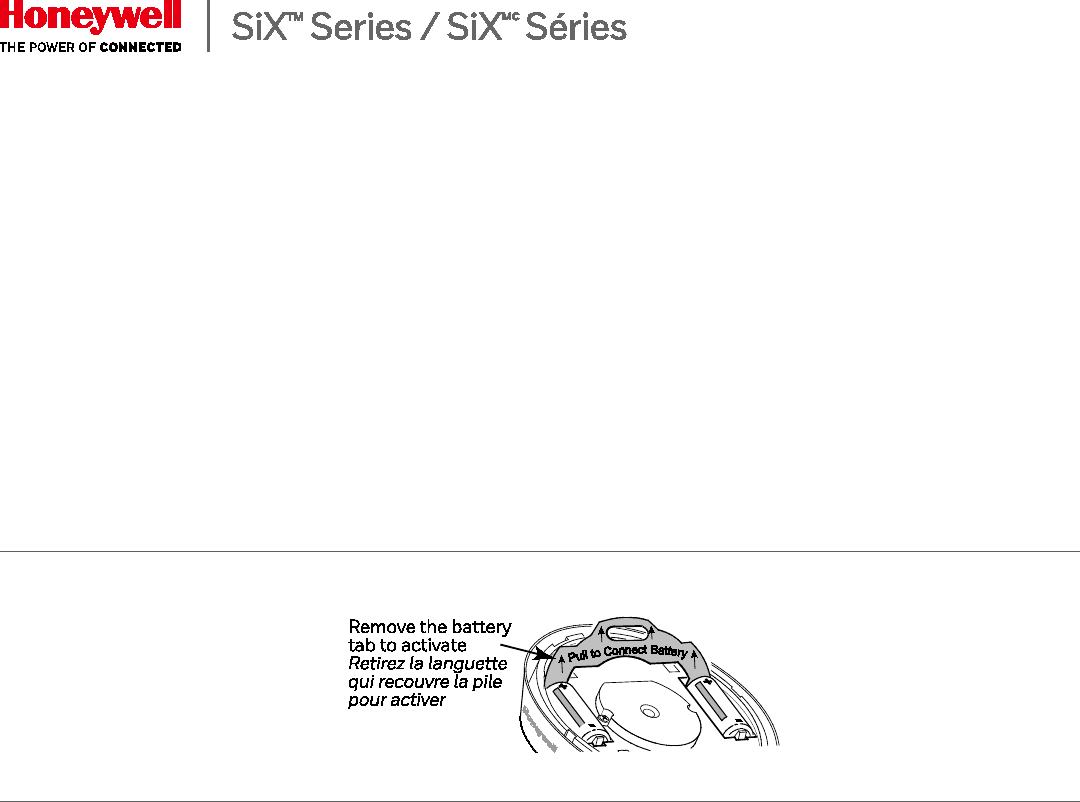
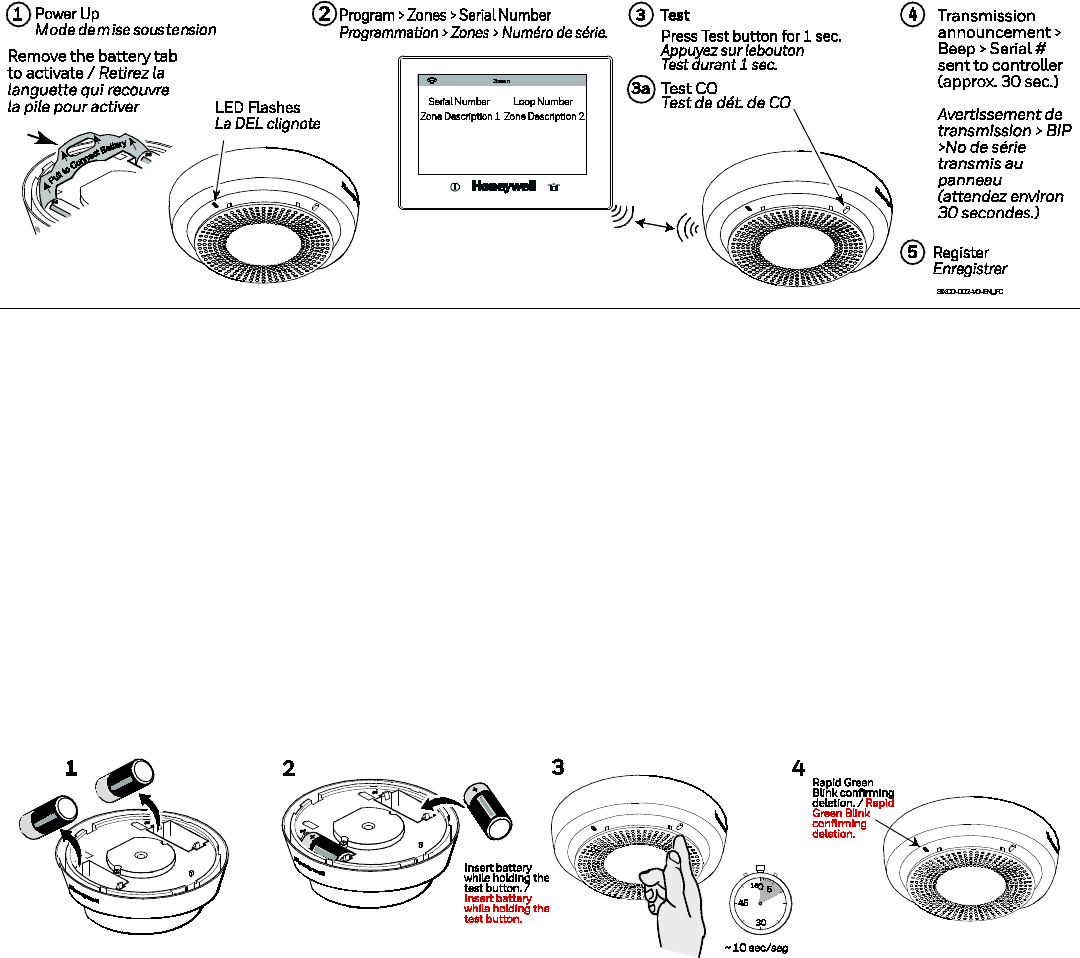
POWER UP
• Remove battery pull tab. Be sure
batteries are seated properly to
avoid a low battery condition
after 15 seconds.
• Upon power up, Green LED
Blinks every 2 secs / Sounder is
Silent.
POWER UP
• Remove battery pull tab. Be
sure batteries are seated
properly to avoid a low
battery condition after 15
seconds.
• Upon power up, Green LED
Blinks every 2 secs /
Sounder is Silent.
ENROLLMENT ENRÔLEMENT
This device can be enrolled and programmed either
before or after installation.
1. Set the Lyric Controller in Programming Mode and go to
Zone Programming. Select Add New and then Serial
Number.
2. Remove the battery tabs to activate the device and begin
the enrollment process.
3. The Green LED flashes rapidly during enrollment (up to
about 20 seconds).
*NOTE: Enrollment time varies depending on the signal
strength between the device and the controller.
• The detector sends its unique MAC ID (Serial Number)
and Services information to the controller.
• The controller registers the device and displays the
transmitter data on screen.
4. Enrollment is confirmed when the Green LED is ON for 3
seconds and the detector chirps.
5. Press SAVE.
Le dispositif peut être enrôlé et programmé avant
ou après l'installation.
1. Réglez le contrôleur Lyric en mode de
programmation et accédez à la programmation
des zones. Sélectionnez Add New (ajouter
nouveau) et ensuite Serial Number (numéro de
série).
2. Retirez la languette qui recouvre la pile pour
activer le dispositif et commencer la procédure
d'enrôlement.
3. La DEL verte clignote durant l'enrôlement
(pendant jusqu'à environ 20 secondes*).
NOTE: La durée de l'enrôlement varie selon la
puissance du signal entre le dispositif et
le contrôleur.
• Le dispositif transmet au contrôleur son ID
MAC (numéro de série) et l'information pour les
services.
• Le contrôleur enregistre le dispositif et affiche
les données du transmetteur sur l'écran.
2
6.
If the detector is not successfully enrolled during the
enrollment period, the LED turns off and the device
powers down. Pressing and holding the test button, while
powering the detector, will arm the detector to perform a
reset to factory defaults.
The device can also be manually enrolled. See the
Controller’s Programming Guide for details.
4. L'enrôlement est confirmé lorsque la DEL verte est
allumée durant 3 secondes et que le dispositif émet
un pépiement .
5. Appuyez sur GARDER (Enregistrer).
6. Si le dispositif n'est pas enrôlé avec succès durant la
période d'enrôlement, la DEL s'éteint et le dispositif
se met hors tension. Pressing and holding the test
button, while powering the detector, will arm the
detector to perform a reset to factory defaults.
Le dispositif peut également être enrôlé manuellement.
Pour les détails, reportez-vous au Guide de
programmation du contrôleur.
24-Hour Enrollment Deletion and Default
If the device is enrolled in a panel different than the
intended panel, and you are unable to delete it from the
unintended panel, reset default the device to factory
default setting:
If the device is enrolled in a panel different than the
intended panel, and you are unable to delete it from the
unintended panel, reset default the device to factory
default setting:
This procedure is available for 24 hours after enrollment
with a panel and the device remains powered (battery
installed).
Remove power from the detector. Press the CO Test
Button. While holding the test button, insert the
batteries. Continue holding the test button for 10
seconds and release. The status LED should start
blinking green rapidly to confirm its deleted enrollment.
3
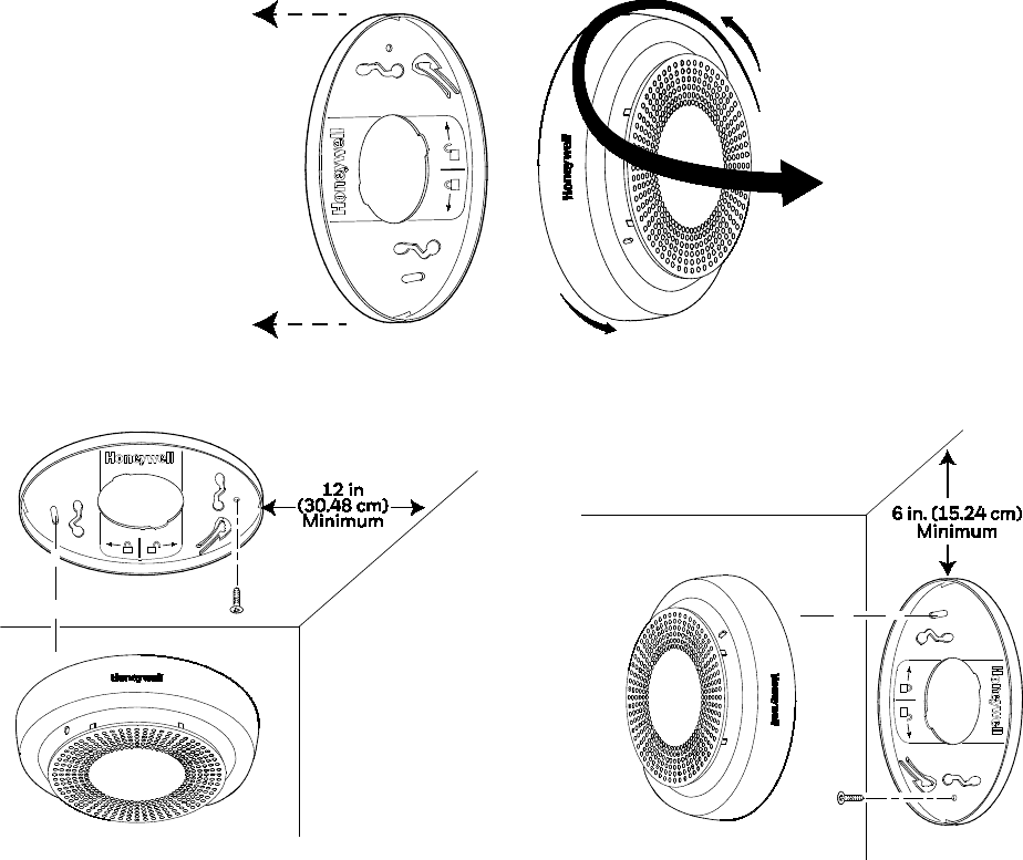
MOUNTING
MONTAGE
After enrolling and before mounting permanently,
conduct Go/No Go test (see controller’s instructions) to
verify adequate signal strength. Adjust the device
location as necessary.
1. Remove the CO with a counter-clockwise motion.
2. Using two supplied screws and anchors, mount the
base.
3. Attach the CO detector to the mounting base with a
clockwise motion.
4. Test each detector as described in the Testing section.
5. Confirm all desired signals have been received by the
Central Station.
NOTE:
NFPA 72 recommends the installation of detectors only
after completing construction or any other dust
producing activity.
Ceiling Mount / Ceiling Mount
Wall Mount / Wall Mount
4
TESTING
Test communications between the detector and the
control panel. The detector has one test button (for
testing CO).
The detector may also be functionally tested using
canned CO. If the detector fails the test method, the
detector should be replaced.
NOTE: Testing the detector will activate the alarm and
send a signal to the panel.
Before testing, notify the proper authorities to avoid any
false alarms.
CO Test (Alarm Test)
Press and hold the CO Test button for 1 to 2 seconds.
The control panel should display and sound a CO alarm
(all programmed CO detector loops are sent).
TESTING
Test communications between the detector and the
control panel. The detector mode has one test button
(for testing CO)
The detector may also be functionally tested using
canned CO. If the detector fails the test method, the
detector should be replaced.
NOTE: Testing the detector will activate the alarm and
send a signal to the panel.
Before testing, notify the proper authorities to avoid any
false alarms.
CO Test (Alarm Test)
Press and hold the CO Test button for 1 to 2 seconds.
The control panel should display and sound a CO
alarm (all programmed CO detector loops are sent).
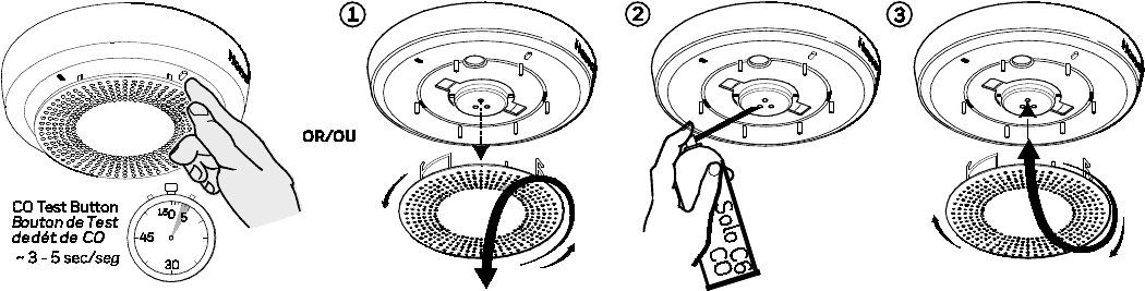
CO System Test (Functional CO Test)
Press and hold the CO Test button for 3-5 seconds to
enter the functional gas test mode. See Functional Gas
Test section below.
Functional Gas Test
Solo C6 brand canned CO may be used to verify the
detector’s ability to sense CO by utilizing the RealTest®
feature as follows:
1. Remove cover by rotating counter clockwise.
2. Press and hold the CO test button for 3 to 5 seconds.
The green LED will start blinking once per second
indicating the detector is in RealTest® mode. (If the
detector will not go into RealTest® mode, the CO
sensor may be in fault or at end-of- life.)
3.
While the green LED is blinking once per second, spray
a small amount of canned CO directly into the CO gas
entry port.
4. Upon successful gas entry and if functioning properly,
the detector will go into CO alarm and send an alarm
to the control panel.
5.
The CO test will automatically clear when the CO clears
from the sensor or in 30 seconds if no CO was
introduced.
6. Reattach the cover to the detector.
CO System Test (Functional CO Test)
Press and hold the CO Test button for 3-5 seconds to
enter the functional gas test mode. See Functional Gas
Test section below.
Functional Gas Test
Solo C6 brand canned CO may be used to verify the
detector’s ability to sense CO by utilizing the RealTest®
feature as follows:
1. Remove cover by rotating counter clockwise.
2. Press and hold the CO test button for 3 to 5 seconds.
The green LED will start blinking once per second
indicating the detector is in RealTest® mode. (If the
detector will not go into RealTest® mode, the CO
sensor may be in fault or at end-of- life.)
3. While the green LED is blinking once per second,
spray a small amount of canned CO directly into the
CO gas entry port.
4. Upon successful gas entry and if functioning
properly, the detector will go into CO alarm and send
an alarm to the control panel.
5. The CO test will automatically clear when the CO
clears from the sensor or in 30 seconds if no CO was
introduced.
6. Reattach the cover to the detector.
5
HUSH FEATURE / ALARM SILENCE
If required, the audible alarm for CO conditions can be
silenced for 5 minutes by pushing the “Test/Hush”
button. In addition, low chirping can be silenced for 12
hours when the Test/Hush button is pressed.
During a CO alarm, if carbon monoxide is still present
after the 5-minute hush period, the alarm will sound.
CO SENSOR END-of-LIFE FEATURE
When the CO sensor has passed end-of-life, a trouble
signal is sent to the controller (if programmed). This
indica
tes that the CO sensor inside the detector must be
replaced. If unresolved for 30 days, the detector will chirp
every 45 seconds. The typical life of the CO sensor is ten
years from the date of manufacture. It is recommended
to periodically check the “Replace by” date located on
the label on the back of the detector head.
CO SENSOR END-of-LIFE FEATURE
When the CO sensor has passed end-of-life, a trouble
signal is sent to the controller (if programmed). This
indicates that the CO sensor inside the detector must be
replaced. If unresolved for 30 days, the detector will chirp
every 45 seconds. The typical life of the CO sensor is ten
years from the date of manufacture. It is recommended to
periodically check the “Replace by” date located on the
label on the back of the detector head.
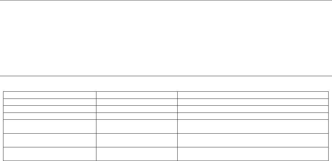
Carbon Monoxide Detector: Events and Their ID Codes
Event
Alpha Keypad
CS Report
CO Alarm / CO Alarm
CO Alarm
CO Alarm (CID 162) / CO Alarm (CID 162)
CO Test / CO Test
CO Alarm
CO alarm (CID 162) / CO Alarm (CID 162)
Low Battery / Low Battery
Lo Bat
RF low-battery (CID 384) / RF Low-Battery (CID 384)
Detector Supervision /
Detector Supervision
CO Trouble
RF sensor supervision (CID 381) / RF sensor
supervision (CID 381)
Detector End-of-Life/Trouble /
Detector End-of-Life/Trouble
CO Trouble
Sensor Trouble - End-of Life (CID 380) / Sensor Trouble
- End-of Life (CID 380)
Tamper / Tamper
Disarmed .......... CO Trouble
Armed ................. CO Alarm
RF Sensor Tamper
(CID 383) / RF Sensor Tamper
TESTING SIGNAL STRENGTH
Perform this test in accordance with NFPA 72
inspection, testing and maintenance requirements to
determine a strong communication path with the control
panel.
1. Activate the wireless system’s GO/NO GO TEST mode.
2. Press the detector’s TEST button (•) for 1-2 seconds.
The detector should immediately transmit an alarm
signal to the control panel. The built-in horn will start
to sound about 2.5 seconds after pressing the button.
3. The wireless system’s keypad should emit at least
three beeps when the alarm transmission is received
and display the transmitting detector’s zone number.
4. When the console has received the test signal, the
horn will stop and a few seconds later the detector’s
zone number will clear from the console display.
5. If the console does not respond as noted, and if this is
an initial installation, try moving the detector to
another location that provides proper reception. Also,
be sure that the detector has been “enrolled” by the
controller (see Enrollment section). Then, repeat the
test.
6. Turn off the system’s TEST mode (typically security
code + OFF).
TESTING SIGNAL STRENGTH
Perform this test in accordance with NFPA 72 inspection,
testing and maintenance requirements to determine a
strong communication path with the control panel.
1. Activate the wireless system’s GO/NO GO TEST mode.
2. Press the detector’s TEST button (•) for 1-2 seconds.
The detector should immediately transmit an alarm
signal to the control panel. The built-in horn will start
to sound about 2.5 seconds after pressing the button.
3. The wireless
system’s keypad should emit at least three
beeps when the alarm transmission is received and
display the transmitting detector’s zone number.
4. When the console has received the test signal, the horn
will stop and a few seconds later the detector’s zone
number will clear from the console display.
5. If the console does not respond as noted, and if this is
an initial installation, try moving the detector to
another location that provides proper reception. Also,
be sure that the detector has been “enrolled” by the
controller (see Enrollment section). Then, repeat the
test.
6. Turn off the system’s TEST mode (typically security
code + OFF).
6
REPLACING THE BATTERIES
Remove old batteries. Wait 10 seconds and then
replace with two new batteries. To avoid a low battery
indication when installing new batteries, both batteries
must be installed within 15 seconds of installing the
first one. Any low battery condition that may have
occurred should clear when the base plate is installed.
REPLACING THE BATTERIES
Re
move old batteries. Wait 10 seconds and then replace
with two new batteries. To avoid a low battery indication
when installing new batteries, both batteries must be
installed within 15 seconds of installing the first one. Any
low battery condition that may have occurred should
clear when the base plate is installed.
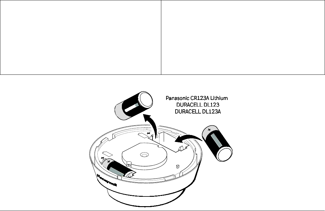
CAUTION!
The batteries used in this device may present a fire or
chemical burn hazard if mistreated. Do not recharge,
disassemble, heat above 100°C (212°F) or dispose
of in fire. Use only Panasonic CR123A OR
DURACELL DL123, DL123A Lithium batteries. Use
of other batteries may present a risk of fire or
explosion. Keep used batteries away from children.
Dispose of used batteries properly.
CAUTION!
The batteries used in this device may present a fire
or chemical burn hazard if mistreated. Do not
recharge, disassemble, heat above 100°C (212°F)
or dispose of in fire. Use only Panasonic CR123A
OR DURACELL DL123, DL123A Lithium batteries.
Use of other batteries may present a risk of fire or
explosion. Keep used batteries away from children.
Dispose of used batteries properly.
BATTERY REPLACEMENT / BATTERY REPLACEMENT
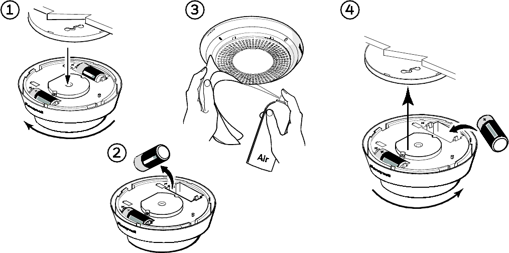
CLEANING
NOTE: Notify the proper authorities when the system
will be temporarily out of service.
IMPORTANT:
This detector must be tested and maintained regularly
following NFPA-72 requirements. The detector
should be cleaned at least once a year.
1.
Remove the detector from the base plate by
turning counterclockwise.
2.
Clean the outside casing with a cloth. Ensure that
the holes on the front of the detector are not
blocked with dirt and dust. Canned air can be used
to remove any dust or debris.
3.
Reattach the detector to the base plate by rotating
clockwise.
4.
Test the detector to insure it is fully functional.
(See Testing section).
Notify the proper authorities and Central Station
when the system is back in service.
CLEANING
NOTE: Notify the proper authorities when the
system will be temporarily out of service.
IMPORTANT:
This detector must be tested and maintained regularly
following NFPA-72 requirements. The detector should
be cleaned at least once a year.
1.
Remove the detector from the base plate by turning
counterclockwise.
Clean the outside casing with a cloth. Ensure that
the holes on the front of the detector are not blocked
with dirt and dust. Canned air can be used to remove
any dust or debris.
2.
Reattach the detector to the base plate by rotating
clockwise.
3.
Test the detector to insure it is fully functional. (See
Testing section).
Notify the proper authorities and Central Station
when the system is back in service.
7
MAINTENANCE
Do not paint, and do not use cleaning agents, bleach
or polish the detector.
NOTE: Before performing any maintenance on the
detector, notify the proper authorities and
Central Station that maintenance is being
performed and the system will be temporarily
out of service. Disable the zone or system
undergoing maintenance to prevent any
unwanted alarms. Power must be removed from
the detector before performing maintenance of
any kind.
The SiXCO detector reports maintenance
issues to the control panel and communicates
them visually and audibly per the table below.
TROUBLE FEATURE
When the sensor (supervision) is in a trouble condition
(such as CO sensor end-of-life), the detector will send
a trouble signal to the control panel. Depending on the
issue, the detector must then be serviced or replaced.
NOTE: CO detectors are not to be used with detector
guards unless the combination is evaluated and
found suitable for that purpose.
MAINTENANCE
Do not paint, and do not use cleaning agents, bleach
or polish the detector.
NOTE: Before performing any maintenance on the
detector, notify the proper authorities and
Central Station that maintenance is being
performed and the system will be temporarily
out of service. Disable the zone or system
undergoing maintenance to prevent any
unwanted alarms. Power must be removed from
the detector before performing maintenance of
any kind.
The SiXCO detector reports maintenance issues
to the control panel and communicates them
visually and audibly per the table below.
TROUBLE FEATURE
When the sensor (supervision) is in a trouble condition
(such as CO sensor end-of-life), the detector will send
a trouble signal to the control panel. Depending on the
issue, the detector must then be serviced or replaced.
NOTE: CO detectors are not to be used with detector
guards unless the combination is evaluated and
found suitable for that purpose.

8
LED INDICATORS / LED INDICATORS
The SiXCO has a multi-color top LED:
Green/Green ...................... Supervisory indication; blinks during power on, reset, and during normal operation /
Supervisory indication; blinks during power on, reset, and during normal operation
Amber / Amber ................. Signal maintenance and trouble events / Signal maintenance and trouble events
Red ......................................... CO Alarm condition / CO alarm condition
MODE
Status LED (Top)
Sounder
RealTest™
Functional CO gas entry test – Waiting for gas
entry / RealTest™
Functional CO gas entry test – Waiting for gas
entry
Blink Green once per second /
Blink Green once per second
Silent / Silent
RealTest™
Functional CO gas entry test -Upon successful
gas entry / RealTest™
Functional CO gas entry test -Upon successful
gas entry
Blink Red once every
10 secs / Blink Red once every
10 secs
Modified Temp-4 / Modified
Temp-4
Low Battery / Low Battery Blink Amber every
45 secs / Blink Amber every
45 secs
Chirp every 45 secs after
7 days / Chirp every 45 secs
after
7 days
CO Trouble / CO Trouble Double Blink Amber every 5
secs / Double Blink Amber
every 5 secs
Silent / Silent
CO End of Life – First 29 days / CO End of Life –
First 29 days
Double Blink Amber every 3
secs / Double Blink Amber
every 3 secs
Silent / Silent
CO End of Life – after 30 days / CO End of Life –
after 30 days
Double Blink Amber every 3
secs / Double Blink Amber
every 3 secs
Chirp every 45 secs / Chirp
every 45 secs
Normal (Standby) / Normal (Standby) Single Blink Green every 10
secs / Single Blink Green every
10 secs
Silent / Silent
Many cases of reported carbon monoxide poisoning
indicate that while victims are aware that they do not
feel well, they become so disoriented that they are
unable to save themselves by either exiting the building
or calling for assistance. Also, young children, elderly
and pets may be the first to be affected.
SYMPTOMS OF CARBON MONOXIDE
POISONING
Carbon monoxide bonds to the hemoglobin in the
blood and reduces the amount of oxygen being
circulated in the body. The following symptoms are
examples taken from NFPA 720; they represent
approximate values for healthy adults.
SYMPTOMS OF CARBON MONOXIDE
POISONING
Carbon monoxide bonds to the hemoglobin in the
blood and reduces the amount of oxygen being
circulated in the body. The following symptoms are
examples taken from NFPA 720; they represent
approximate values for healthy adults.

9
LIMITED LIFE OF CO SENSOR
This detector is manufactured with a long-life
electrochemical carbon monoxide sensor. Over time the
sensor will lose sensitivity and will need to be replaced.
The life span of the CO sensor is approximately ten years
from the date of manufacture.
Periodically check the detector’s replacement date.
Remove the detector head and refer to the ‘replace by’
sticker placed on the underneath side of the detector.
The sticker will indicate the date the detector should be
replaced.
Reminder: This detector is also equipped with a feature
that will signal the panel once the CO sensor has passed
the end of its’ useful life. If this occurs, it is time to
replace the detector.
What to do if the detector goes into CO alarm:
If the detector goes into CO alarm (4 beeps),
immediately move to a spot where fresh air is available,
preferably outdoors, where the air is safe and call your
security service provider. Tell your provider the detector
alarm status, and that you require professional
assistance in ridding your home of the carbon
monoxide.
This detector is NOT:
• A substitute for the proper servicing of fuel-burning
appliances or the sweeping of chimneys.
• To be used on an intermittent basis or as a portable
alarm for the spillage of combustion products from
fuel-burning appliances or chimneys.
Carbon monoxide gas is a highly poisonous gas which
is released when fuels are burnt. It is invisible, has no
smell and is therefore is impossible to detect with the
human senses. Under normal conditions in a room
where fuel burning appliances are well maintained and
correctly ventilated, the amount of carbon monoxide
released into the room by appliances should not be
dangerous.
LIMITED LIFE OF CO SENSOR
This detector is manufactured with a long-life
electrochemical carbon monoxide sensor. Over time the
sensor will lose sensitivity and will need to be replaced.
The life span of the CO sensor is approximately ten years
from the date of manufacture.
Periodically check the detector’s replacement date.
Remove the detector head and refer to the ‘replace by’
sticker placed on the underneath side of the detector. The
sticker will indicate the date the detector should be
replaced.
Reminder: This detector is also equipped with a feature
that will signal the panel once the CO sensor has passed
the end of its’ useful life. If this occurs, it is time to replace
the detector.
What to do if the detector goes into CO alarm:
If the detector goes into CO alarm (4 beeps),
immediately move to a spot where fresh air is available,
preferably outdoors, where the air is safe and call your
security service provider. Tell your provider the detector
alarm status, and that you require professional
assistance in ridding your home of the carbon
monoxide.
This detector is NOT:
• A substitute for the proper servicing of fuel-burning
appliances or the sweeping of chimneys.
• To be used on an intermittent basis or as a portable
alarm for the spillage of combustion products from
fuel-burning appliances or chimneys.
Carbon monoxide gas is a highly poisonous gas which is
released when fuels are burnt. It is invisible, has no smell
and is therefore is impossible to detect with the human
senses. Under normal conditions in a room where fuel
burning appliances are well maintained and correctly
ventilated, the amount of carbon monoxide released into
the room by appliances should not be dangerous.
Concentration (ppm CO) /
Concentration (ppm CO) Symptoms / Symptoms
200 Mild Headache after 2-3 hours of exposure / Mild Headache after 2-3 hours of
exposure
400 Headache and nausea after 1-2 hours of exposure / Headache and nausea after 1-2
hours of exposure
800 Headache, nausea, and dizziness after 45 minutes of expo- sure; collapse and
unconsciousness after 2 hours of exposure / Headache, nausea, and dizziness after
45 minutes of expo- sure; collapse and unconsciousness after2 hours of exposure

10
CO ALARM ACTIVATION
Per UL standard 2075, the SiXCO detector has been
tested to the sensitivity limits defined in UL standard
2034.
CO ALARM ACTIVATION
Per UL standard 2075, the SiXCO detector has been
tested to the sensitivity limits defined in UL standard
2034.
CO Alarm Thresholds / CO Alarm Thresholds
Parts per Million / Parts per Million
Detector Response Time (Minutes) / Detector Response Time (Minutes)
30 +/- 3ppm
No alarm within 30 days / No alarm within 30 days
70 +/- 5ppm
60 - 240
150 +/- 5ppm
10 - 50
400 +/- 10ppm
4 - 15
SPECIFICATIONS / SPÈCIFICATIONS
Electrical Specifications
Voltage / Voltage .......................................................................................................... 3 volts DC
Battery Type / Pile Type ............................................................................................ CR123A OR DURACELL DL123, DL123A lithium
Battery Manufacturer / Pile Manufacturer ..................................................... Panasonic, DURACELL
Number of Batteries / Number of Batteries ................................................... 2
Sensitivity / Sensitivity .............................................................................................. Meets UL2034/UL2075 CO sensitivity requirements
Audible Signal / Audible Signal ............................................................................. 85dBA
Physical Specifications
Diameter / Diameter .................................................................................................. 5.3 inches (13.46cm) Diameter; 1.65 inches (4.19cm) Thick
Weight / Weight ............................................................................................................ 7.7oz. (21g)
Operating Temperature / Température de Fonctionnement ........... 32° – 122° F / 0° – 50° C
Storage Temperature / Storage Temperature .............................................. -10 - 70° C (14 - 158° F)
Operating Humidity / Operating Humidity ..................................................... 20-95% RH
Tamper/Tamper ........................................................................................................... Wall Tamper/Wall Tamper
REFER TO THE INSTALLATION INSTRUCTIONS FOR THE CONTROL WITH WHICH THIS DEVICE IS USED, FOR
DETAILS REGARDING LIMITATIONS OF THE ENTIRE ALARM SYSTEM.
POUR LES LIMITES DU SYSTÈME D’ALARME AU COMPLET, REPORTEZ-VOUS AU GUIDE D’INSTALLATION DU
PANNEAU DE COMMANDE.

11
RF EXPOSURE
Warning – The antenna(s) used for this device must be installed to provide a separation distance of at least 7.8 inches (20 cm)
from all persons and must not be co-located or operating in conjunction with any other antenna or transmitter except in
accordance with FCC multi-transmitter product procedures.
Mise en Garde
Exposition aux Fréquences Radio: La/les antenne(s) utilisée(s) pour cet émetteur doit/doivent être installée(s) à une distance
de séparation d'au moins 20 cm (7,8 pouces) de toute personne et ne pas être située(s) ni fonctionner parallèlement à tout
autre transmetteur ou antenne, excepté en conformité avec les procédures de produit multi transmetteur FCC et ISED.
FEDERAL COMMUNICATIONS COMMISSION (FCC) & INDUSTRY CANADA (IC) STATEMENTS
The user shall not make any changes or modifications to the equipment unless authorized by the Installation Instructions or
User's Manual. Unauthorized changes or modifications could void the user's authority to operate the equipment.
FCC / IC STATEMENT
This device complies with Part 15 of the FCC Rules, and Industry Canada’s license-exempt RSSs. Operation is subject to the
following two conditions: (1) This device may not cause harmful interference, and (2) This device must accept any interference
received, including interference that may cause undesired operation.
Cet appareil est conforme à la partie 15 des règles de la FCC et exempt de licence RSS d’Industrie Canada. Son
fonctionnement est soumis aux conditions suivantes: (1) Cet appareil ne doit pas causer d’interférences nuisibles. (2) Cet
appareil doit accepter toute interférence reçue y compris les interférences causant une réception indésirable.
Approval Listings / Approbations homologations
FCC/ICC
ETL Listed to UL2075 and CSA 6.19 MAR2001 (R2016)
Other Standards
RoHS

SUPPORT, WARRANTY, & PATENT INFORMATION
For online support information, please go to:
https://mywebtech.honeywell.com/
Pour de l’assistance en ligne, visitez :
https://mywebtech.honeywell.com/
For the latest warranty information, go to:
www.honeywell.com/security/hsc/resources/wa
Pour les dernières informations de garantie, s'il vous plaît aller à :
www.honeywell.com/security/hsc/resources/wa
For patent information, see www.honeywell.com/patents
Pour des informations sur les brevets,
voir www.honeywell.com/patents
MyWebTech
Warranty
Patents
Ê800-23974lŠ
800-23974 1/18 Rev A
2017 Honeywell International Inc. Honeywell and is a registered trademark of Honeywell International
Inc. All other trademarks are the properties of their respective owners. All rights reserved.
Honeywell est une marque déposée de Honeywell International Inc. Toutes les autres marques de
commerce appartiennent à leurs propriétaires respectifs. Tous droits réservés.