Ademco 8DLCOMSR COMBO 5800 User Manual Installation Instructions
Honeywell International Inc. COMBO 5800 Installation Instructions
Ademco >
Contents
- 1. Installation Instructions
- 2. Quick Install Guide USA
Installation Instructions
This is intended for use with Honeywell control
panels that support 5800 series devices.
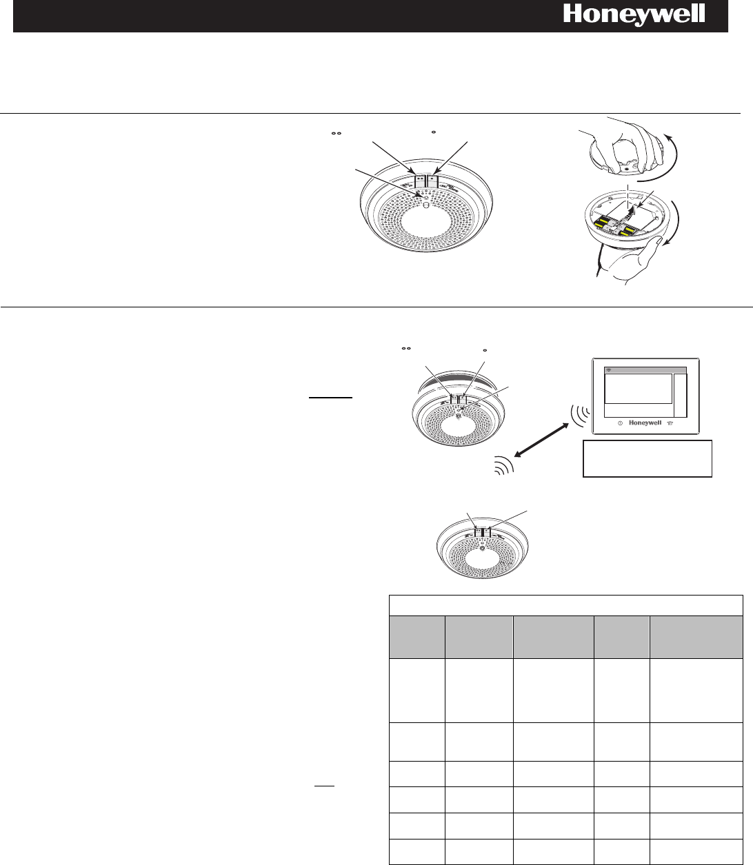
Install
•
Remove Battery Pull tabs to activate device and
begin enrollment.
• The detector will run through its Power-Up
mode: Green LED Blinks every 2 secs /
Sounder is Silent. The detector will prompt for
language selection.
Important Note: CO and SMOKE each have
unique serial numbers and must to be enrolled
separately.
CO Test
LED
Smoke Test
5800combo-ii 001
( ) ( )
5800COMBO
5800combo-ii 002
Pull Battery Tab
Open
Top
Open
Enroll
1.
Press the Smoke (•) test button to select English or the CO
(••) test button to select Spanish language settings.
2.
On the Honeywell compatible control panel, log in
Programming Mode > Zones > New > Serial Number.
3.
Enter the zone number to be programmed for Smoke.
4.
Enter zone type when prompted. Program:
• Loop 1 (Heat/Smoke) as a Fire zone (type 9 or 16),
• Loop 2 (High/Low Maintenance) as a 24-Hr. Trouble zone
(type 19),
• Loop 3 (Freeze Warning Sensor) as a 24-Hr. Aux. zone
(type 8).
NOTE: Loop 2 High/Low Maintenance is supported only on
commercial control panels such as the Vista-128FBP.
5.
When prompted, enter Input Type 03 (3 on some controls) –
Supervised RF Transmitter.
6.
When prompted for the serial number, activate the sensor
(press for 1 sec.) or enter the serial number found on the
label located on the unit. The unit will speak, then beep and
the serial number will be transmitted to the panel. (This will
take approx. 40 secs.) Repeat this step to complete
enrollment.
7.
The current loop number (4) will begin to flash.
8.
Manually change the loop number to the desired loop
number for the zone, loop (1) is for Heat/Smoke.
9.
When programming for the Heat/Smoke Loop 1 zone type is
complete, program other zones for the types as necessary in
additional zones (except for Tamper Loop 4, which does not
require programming).
WARNING: The fire protection zone enrolled must always be Loop
1. Otherwise, fire annunciations will not be reported by the control.
10.
Enter the zone number to be programmed for CO.
11.
Enter the applicable zone type. Use zone type 14 for
Honeywell residential controls.
12.
Enter Input Type 03 (3 on some controls)–Supervised RF
Transmitter.
13.
When prompted for the serial number, activate the sensor
(press for 1 sec.) or enter the serial number found on the
label located on the unit. The unit will speak, then beep and
the serial number will be transmitted to the panel. (This will
take approx. 40 secs.) Repeat this step to complete
enrollment.
14.
Check that the CO detector is enrolled as loop 1.
15.
Exit Programming mode and test the detector. Refer
to the Testing Section.
2
Serial Number Loop Number
Zone Description 1 Zone Description 2
Zone n
Save
5
Programming Mode
Zones > New > Serial Numbers.
LED Flashes
3a) Test CO 3b) Test Smoke
5800 combo-ii-003
1
Power -Up mode
( ) English
( ) Spanish
French
Transmission announcment >
Beep > Serial # sent to panel
(approx. 40 secs)
● Repeat Step 3.
4
Press Test button for < 1.5 secs
3
Test
or
2 Times
Enter the unique Serial number(s)
found on the label located on the
unit. See Important Note above.
Visible Annunciation
The 5800COMBO Smoke/CO series detector has a multi-color
top LED; Green, Red, Blue and Amber. The LED is green for
supervisory indication; it blinks during power on, reset, and
during normal operation. The LED is amber to signal
maintenance and trouble events. The detector utilizes the side
LED windows to indicate alarm events; red for smoke and blue
for CO.
Table 1: Operation Modes
MODE Status LED
(Top)
LED Windows
(Side)
Sounder Speaker
Power Up
Blink Green,
every 2 secs
Dark Silent
Voice welcome,
instructions follow
POR for language
selection, enrollment,
testing
Normal
(Standby)
Single Blink
Green every
10 secs
Dark Silent Silent
Smoke
Alarm
Blink Red
every 10 secs Blink red Temp-3
Voice smoke
warning
Thermal
Alarm Dark Blink red Temp-3
Voice smoke
warning
CO Alarm
Blink Red
every 10 secs Blink blue Temp-4
Voice CO
warning
Powered
Down Dark Dark Silent Silent
Model: 5800COMBO with voice and 360 degree viewable LED ring
Combination Smoke/Carbon Monoxide (CO) Detector with Built-in Wireless Transmitter
INSTALLATION AND SETUP GUIDE
2
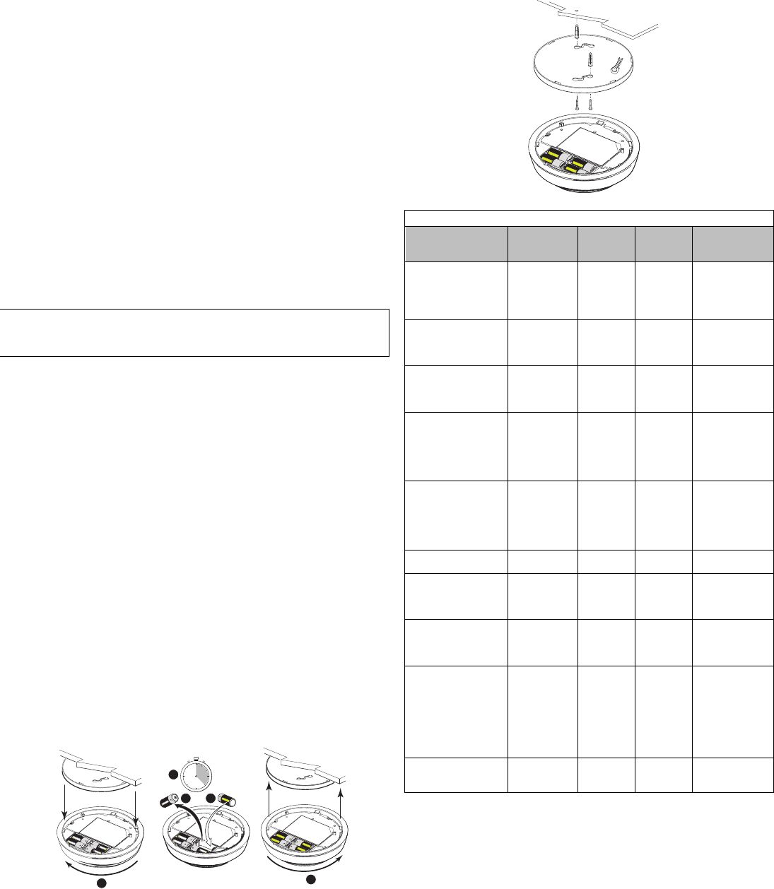
Mounting
After enrolling and before mounting permanently, conduct Go/No Go
test (see controller’s instructions) to verify adequate signal strength.
Adjust the device location as necessary.
Physically mount the smoke detector in the desired location;
1. Using two supplied screws and anchors, mount the base.
2. Attach the smoke detector to the mounting base with a clockwise
motion.
3. Test each detector as described in the Testing section.
4. Confirm all desired signals have been received by the Central
Station.
NOTE: NFPA 72 recommends the installation of detectors only after
completing construction or any other dust producing activity
.
5800 combo-QG-004
Testing
Test communications between the detector and the control panel.
The detector mode has two test buttons; one for smoke testing and
one for CO testing.
The detector may also be functionally tested using canned smoke
and canned CO. If the detector fails any of the test methods, the
detector should be replaced.
NOTE: Testing the detector will activate the alarm and send a signal
to the panel. Before testing, notify the proper authorities to avoid
any false alarms.
Smoke Test
Press and hold the Smoke Test button for 3 to 5 seconds. The
detector will sound and illuminate per Table 2 and send a smoke
alarm signal to the control panel.
Verify that the smoke alarm signal was received at the control
panel.
To functionally test the smoke sensor see Smoke Entry Test section.
CO Test
Press and hold the CO Test button for 3 to 5 seconds to enter a
functional gas test mode. See Functional Gas Test section.
The control panel alarm and all auxiliary functions should be
verified for a complete test of the system.
Smoke Entry Test
1. With the detector in standby mode, spray canned smoke into the
detector. The canned smoke that can be used and is approved
for test include: Home Safeguard Industries 25S, SDi CHEK02
and CHEK06, SDi SOLOA4, and SDi SMOKESABRE.
2. The detector will sound and illuminate per Table 2 and a smoke
alarm signal will be sent to the panel.
3. Verify the smoke alarm signal was received by the control panel.
Smoke Sensitivity Reading
When the Smoke Test button is pressed for 3 to 5 seconds, the
detector will vocally annunciate its smoke sensitivity along with
diagnostic information.
Replace Battery
5800combo QG-006
23
11 5
4
30
0
45
20
10
Panasonic CR123A
~ 10
sec / seg
Caution: The batteries used in this device may present a fire or
chemical burn hazard if mistreated. Do not recharge, disassemble,
heat above 100°C (212°F) or dispose of in fire. Use only
Panasonic CR123A Lithium batteries. Remove old batteries. Wait
10 seconds and then replace with four new batteries. Use of other
batteries may present a risk of fire or explosion. Keep used
batteries away from children. Dispose of used batteries properly.
Restore Factory Settings
Press and hold both the Smoke and CO test switch
simultaneously for 10 seconds, then release. The green light
will flash rapidly. Press and hold both buttons again for one
second and release. The sensor will begin speaking.
Table 2: LED Indication & Sounder during Test and Maintenance
MODE
Status LED
(Top)
Side LED
Windows
Sounder Speaker
Smoke Alarm
System Test Dark Dark Temp-3
Warning of
alarm signal
transmission.
Voice smoke
warning
RealTest™
Functional CO gas
entry test - Waiting
for gas entry
Blink Red
once a
second
Dark Silent
Voice
instructions for
testing; warning
of alarm signal
RealTest™
Functional CO gas
entry test -Upon
successful gas entry
Blink Red
every
10 secs
Blink blue
every
10 secs
Modified
Temp-4
Voice carbon
monoxide
warning
Low Battery
Blink Amber
every
10 secs
Dark
Chirp every
45 seconds
after 7 days
Voice
instructions
when chirp is
hushed by
pressing either
test button
Smoke
Maintenance
Blink Amber
every 5 secs Dark Silent
Voice smoke
maintenance
instructions if
either test
button is
pressed
CO Trouble Blink Amber
every 5 secs Dark Silent
CO End of Life -
First 29 days
Blink Amber
every 3 secs Dark Silent
Voice end of life
instructions;
press
either test
button
CO End of Life -
after 30 days
Blink Amber
every 3 secs Dark
Chirp
every 45
Seconds
Voice end of life
instructions;
press either
test
button
Power Up Blink Green,
every 2 secs
Dark Silent
Voice
welcome,
instructions
follow POR for
language
selection,
enrollment,
testing
Normal (Standby)
Single Blink
Green every
10 sec
Dark Silent Silent
3
Functional Gas Test
Solo C6 brand canned CO may be used to verify the detector’s ability
to sense CO by utilizing the RealTest® feature as follows:
1.
Press and hold the CO test button for 3 to 5 seconds. The green
LED will start blinking rapidly indicating the detector is in
RealTest® mode. (If the detector will not go into RealTest® mode,
the CO sensor may be in fault or at end-of-life.)
2.
While the green LED is blinking rapidly, spray a small amount of
canned CO directly into the CO gas entry port.
3.
Upon successful gas entry and if functioning properly, the detector
will go into CO alarm and send an alarm to the control panel.
4.
The CO test will automatically clear when the CO clears from the
sensor or in 30 seconds if no CO was introduced.
Hush feature / Alarm Silence: If required, the audible alarm can be
silenced for 5 minutes by pushing the button marked “Test/Hush”.
During a Smoke alarm, if an alarm condition still exists after the 5
minute hush period, the alarm will sound. The hush facility will not
operate at levels above 4%/ft smoke concentration.
During a CO alarm, if carbon monoxide is still present after the 5
minute hush period, the audible alarm will sound. The hush facility will
not operate at levels above 350 ppm (parts per million) carbon
monoxide.
CO sensor end-of-life timer feature: When the CO sensor has
passed end-of-life, a trouble signal will be sent to the control panel.
This indicates that the CO sensor inside the detector must be
replaced. If unresolved for 30 days, the detector will chirp
intermittently. The typical life of the CO sensor is ten years from the
date of manufacture; it is recommended to periodically check the
“Replace by” date located on the label on the back of the detector
head.
Testing Signal Strength
Perform this test in accordance with NFPA 72 inspection, testing and
maintenance requirements to determine a strong communication path
with the control panel.
1. Activate the wireless system’s GO/NO GO TEST mode from the
keypad.
2. Press and hold the detector’s Smoke TEST button (•). The detector
should immediately transmit an alarm signal to the control panel.
The built-
in horn will start to sound about 2.5 seconds after pressing
the button.
3. The wireless system’s keypad should emit at least three audible
sounds when the alarm transmission is received
and will display the
transmitting detector’s zone number.
4. When the console has received the test signal, release the TEST
button. The horn will immediately stop and a few seconds later the
detector’s zone number will clear from the console display.
5. If the console does not respond as noted, check the polarity of the
battery and be sure it is fresh. If this is an initial installation, try
moving the detector to another location that provides proper
reception. Also be sure that the detector has been “enrolled” by the
control panel (see Enroll section). Then, repeat the test.
6. Turn off the system’s TEST mode from the keypad (security code +
OFF).
Do not paint, and do not use cleaning agents, bleach or polish the detector.
*
SMOKE
CO Test
Button
Smoke Test
Button
Solo C6
CO
5800 combo ii -005
1
2
3
4
or
HEAT
≥ 12”
(30.48 cm)
Follow instructions
on the Can
Test
Cleaning
Note: Notify the proper authorities when the system will
be temporarily out of service.
1.
Remove the detector head by turning
counterclockwise.
2.
Clean the outside casing with a cloth. Ensure that the
holes on the front of the alarm are not blocked with dirt
and dust. Canned air can be used to remove any dust
or debris.
3.
Reattach the detector head to the mounting base by
rotating clockwise.
4.
Test the detector to insure it is fully functional. (See
Testing section).
5.
Notify the proper authorities and Central Station when
the system is back in service.
Table 3: Carbon Monoxide Detector: Events and Their ID Codes
Event Alpha Keypad
CS Report
CO alarms CO Alarm
CO alarm (CID 162)
CO test CO Alarm
CO alarm (CID 162)
Low battery Lo Bat RF low-battery (CID 384)
detector
supervision
CO Trouble RF sensor supervision
(CID 381)
detector end-of-
life/trouble CO Trouble sensor trouble - end-of life
(CID 380)
tamper disarmed = CO Trouble
armed = CO Alarm
RF sensor tamper
(CID 383)
Maintenance
The 5800COMBO detector reports maintenance issues to the control panel and communicates them visually and audibly per Table 2.
Trouble feature: When the sensor (supervision) is in a trouble condition (such as a detector that is dirty or CO sensor non-functioning), the
detector will send a trouble signal to the control panel. Depending on the issue, the detector must then be serviced or replaced.
NOTE: Before performing any maintenance on the detector, notify the proper authorities and Central Station that maintenance is being performed and the system
will be temporarily out of service. Disable the zone or system undergoing maintenance to prevent any unwanted alarms. Power must be removed from the
detector before performing maintenance of any kind.
NOTE: Smoke detectors are not to be used with detector guards unless the combination is evaluated and found suitable for that purpose.
4
LIMITED LIFE OF CO SENSOR
This detector is manufactured with a long-life electrochemical carbon monoxide
sensor. Over time the sensor will lose sensitivity and will need to be replaced.
The life span of the CO sensor is approximately ten years from the date of
manufacture.
Periodically check the detector’s replacement date. Remove the detector head
and refer to the ‘replace by’ sticker placed on the underneath side of the
detector. The sticker will indicate the date the detector should be replaced.
Reminder: This detector is also equipped with a feature that will signal the
panel once the CO sensor has passed the end of its’ useful life. If this occurs,
it is time to replace the detector.
What to do if the detector goes into CO alarm:
If the detector goes into CO alarm (4 beeps), immediately move to a spot where
fresh air is available, preferably outdoors, where the air is safe and call your
security service provider. Tell your provider the detector alarm status, and that
you require professional assistance in ridding your home of the carbon
monoxide.
This detector is NOT:
•
A substitute for the proper servicing of fuel-burning appliances or the
sweeping of chimneys.
•
To be used on an intermittent basis or as a portable alarm for the spillage
of combustion products from fuel-burning appliances or chimneys.
Carbon monoxide gas is a highly poisonous gas which is released when fuels
are burnt. It is invisible, has no smell and is therefore is impossible to detect
with the human senses. Under normal conditions in a room where fuel burning
appliances are well maintained and correctly ventilated, the amount of carbon
monoxide released into the room by appliances should not be dangerous.
FEDERAL COMMUNICATIONS COMMISSION & INDUSTRY CANADA
STATEMENTS
The user shall not make any changes or modifications to the equipment unless
authorized by the Installation Instructions or User's Manual. Unauthorized changes or
modifications could void the user's authority to operate the equipment.
FCC / IC STATEMENT
This device complies with Part 15 of the FCC Rules, and RSS-210 of Industry
Canada. Operation is subject to the following two conditions: (1) This device may not
cause harmful interference, and (2) This device must accept any interference
received, including interference that may cause undesired operation.
Cet appareil est conforme à la partie 15 des règles de la FCC & de RSS-210 des
Industries Canada. Son fonctionnement est soumis aux conditions suivantes: (1) Cet
appareil ne doit pas causer d’interférences nuisibles. (2) Cet appareil doit accepter
toute interférence reçue y compris les interférences causant une réception
indésirable.
RF EXPOSURE WARNING – The antenna(s) used for this device must be installed
to provide a separation distance of at least 7.8 inches (20 cm) from all persons and
must not be co-located or operating in conjunction with any other antenna or
transmitter except in accordance with FCC multi-transmitter product procedures.
MISE EN GARDE EXPOSITION AUX FREQUENCES RADIO: L'antenne (s)
utilisée pour cet émetteur doit être installée à une distance de séparation d'au
moins 7,8 pouces (20 cm) de toutes les personnes.
This product is intended for use with Honeywell controls that support 5800 series devices.
SUPPORT & WARRANTY
For the latest documentation and online support information, please go to:
https://mywebtech.honeywell.com/
For the latest warranty information, please go to:
www.honeywell.com/security/hsc/resources/wa.
For patent information, see www.honeywell.com/patents
MyWebTech
Warranty
Patents
REFER TO THE INSTALLATION INSTRUCTIONS FOR THE CONTROL WITH WHICH THIS DEVICE IS USED FOR DETAILS REGARDING THE LIMITATIONS OF THE
ENTIRE ALARM SYSTEM.
Symptoms of Carbon Monoxide Poisoning
Carbon monoxide bonds to the hemoglobin in the blood and reduces
the amount of oxygen being circulated in the body. The following
symptoms are examples taken from NFPA 720; they represent
approximate values for healthy adults.
Concentration
(ppm CO) Symptoms
200 Mild Headache after 2-3 hours of exposure
400 Headache and nausea after 1-2 hours of exposure
800 Headache, nausea, and dizziness after 45 minutes of expo-
sure; collapse and unconsciousness after 2 hours of exposure
Many cases of reported carbon monoxide poisoning indicate that while
victims are aware that they do not feel well, they become so disoriented
that they are unable to save themselves by either exiting the building or
calling for assistance. Also young children, elderly and pets may be the
first to be affected.
CO Alarm Activation
Per UL standard 2075, the 5800COMBO
detector has been tested to the
sensitivity limits defined in UL standard 2034.
CO Alarm Thresholds
Parts per Million
Detector Response Time (Min.)
30+-3ppm No alarm within 30 days
70+-5ppm 60-240
150+-5ppm 10-50
400+-10ppm 4-15
Specifications Voice
Electrical Specifications
Voltage: 3 volts DC
Battery Type: CR123A lithium
Battery Manufacturer: Panasonic CR123A only
Number of Batteries: 4
Sensitivity : UL limits .9 to 2.84%/ft / ULC limits .9 to 2.64 %/ft
Thermal alarm: 135° F (57° C)
Freeze trouble: 41° F typical (5° C)
Audible Signal: 85dBA
Physical Specifications
Diameter: 16.002 cm x 4.19 cm Thick / 6.3 in. Diameter x 1.65 in. Thick
Weight: : 14.3 oz; 406 g
Operating Temperature Range: 32° – 122° F / 0° – 50° C
Storage Temperature Range: -10 - 70° C (14 - 158° F)
Operating Humidity Range: 20-95% RH
Approval Listings:
FCC / IC
Listed to UL 268, UL 521 & UL 2075.
Listed to ULC-S530, ULC-S531 & CSA 6.19.
Other Standards: RoHS
Agile ref. #800
-22142 9/16 Rev A
I56-6250-001
2 Corporate Center Drive, Suite 100
P.O. Box 9040, Melville, NY 11747
© Honeywell International Inc., 2016
www.honeywell.com/security