Ademco 8DLGW Harmony Gateway User Manual Lynx R24 Lynx R
Honeywell International Inc. Harmony Gateway Lynx R24 Lynx R
UserManual.wiki
>
Ademco
>
8DLGW User Manual
>
Installation Manual
Contents
1.
Installation Manual
2.
Quick User Guide
Installation Manual
Navigation menu
Upload a User Manual
Namespaces
Wiki Guide
HTML
PDF
Info
Views
User Manual
Discussion / Help
Navigation

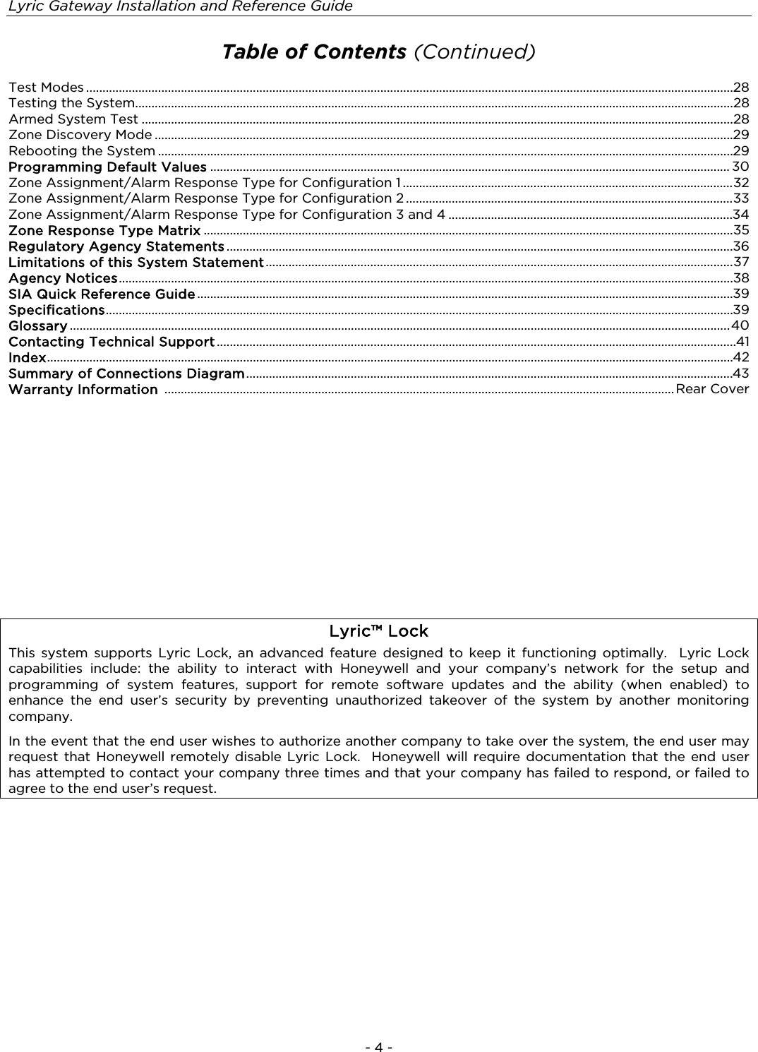
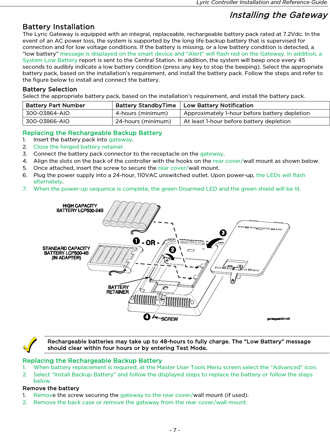
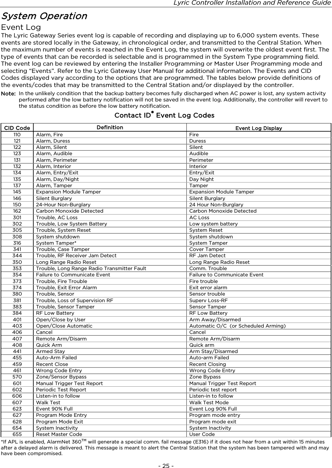
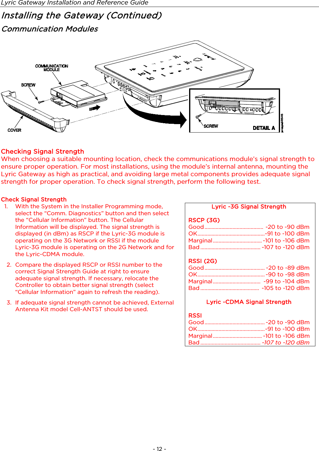
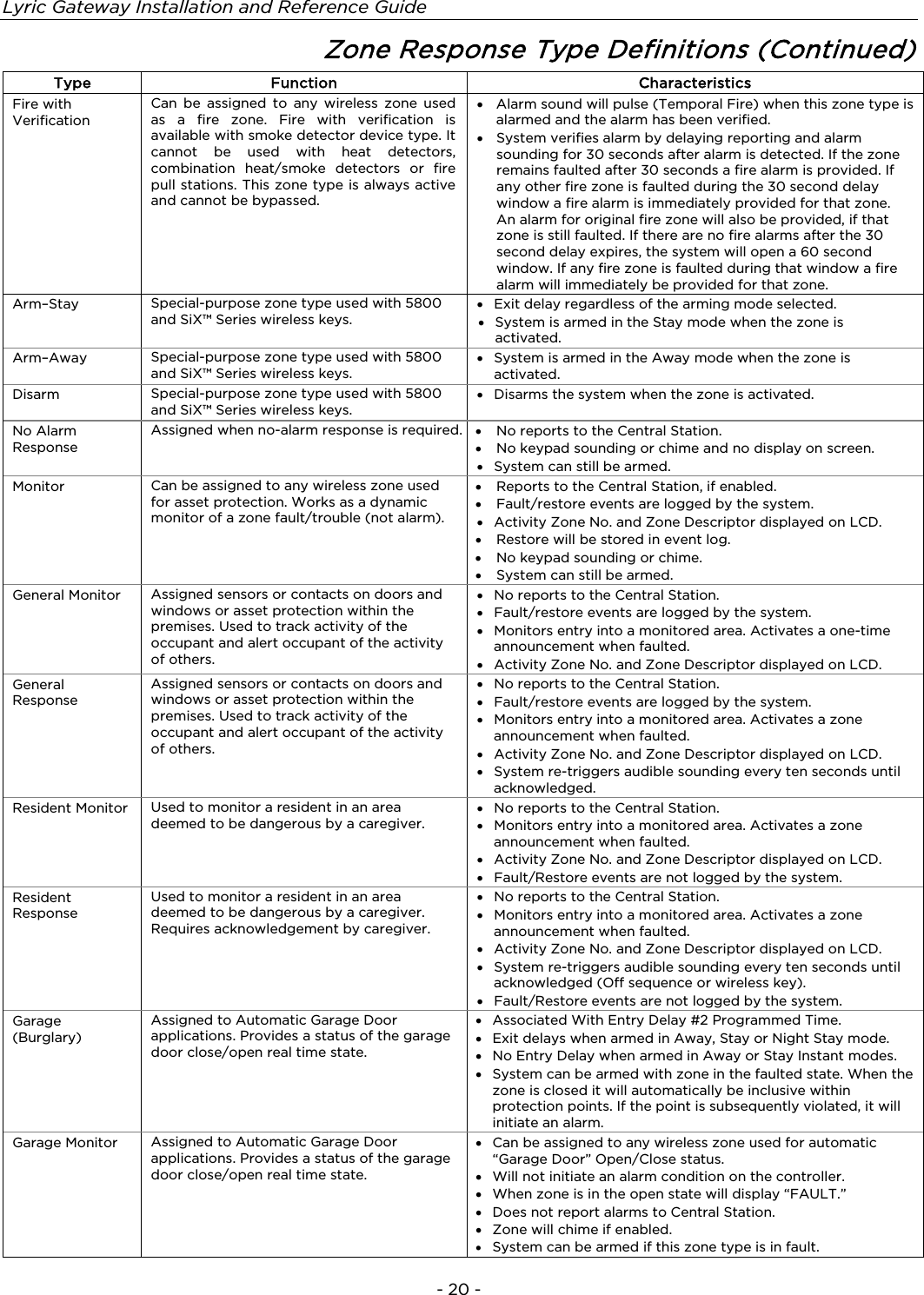
![Lyric Gateway Installation and Reference Guide - 8 - Installing the Gateway (Continued) 3. Disconnect the battery pack connector from the receptacle on the back of the gateway. 4. Open the hinged battery retainer. 5. Remove the battery pack from the Gateway. Install the replacement battery 1. Install a replacement battery pack (LCP500-4B [p/n 300-03864-AIO] OR LCP500-24B [p/n 300-03866-AIO]) into the gateway. 2. Close the hinged battery retainer. 3. Connect the battery pack connector to the receptacle on the gateway. 4. Align the slots on the back of the controller with the hooks on the rear cover/wall mount as shown below. 5. Once attached, insert the screw to secure the rear cover/wall mount. 6. Plug the power supply into a 24-hour, 110VAC unswitched outlet. Upon power-up, the LEDs will flash alternately. 7. When the power-up sequence is complete, the green Disarmed LED and the green shield will be lit. NOTE: If a Cellular Communication Module is being installed, verify the module’s signal strength before selecting a final mounting location. Refer to Checking the Signal Strength in the Communications Module section. Wall Mounting NOTE: When selecting a location for the Lyric Controller, be sure to provide a separation of at least 10 feet between 2.4GHz devices such as Wi-Fi Routers/Access Points. For wall mounting follow the steps and refer to the figure below. 1. Feed the field wiring through the appropriate openings in the wall mount. 2. Attach the wall mount to a sturdy wall using the four provided screws. 3. If required, install an additional mounting screw in the case tamper. 4. Align the slots on the back of the controller with the hooks on the wall mount as shown below. 5. Once attached, insert the screw to secure the Lyric to the wall mount.](https://usermanual.wiki/Ademco/8DLGW.Installation-Manual/User-Guide-3152410-Page-8.png)
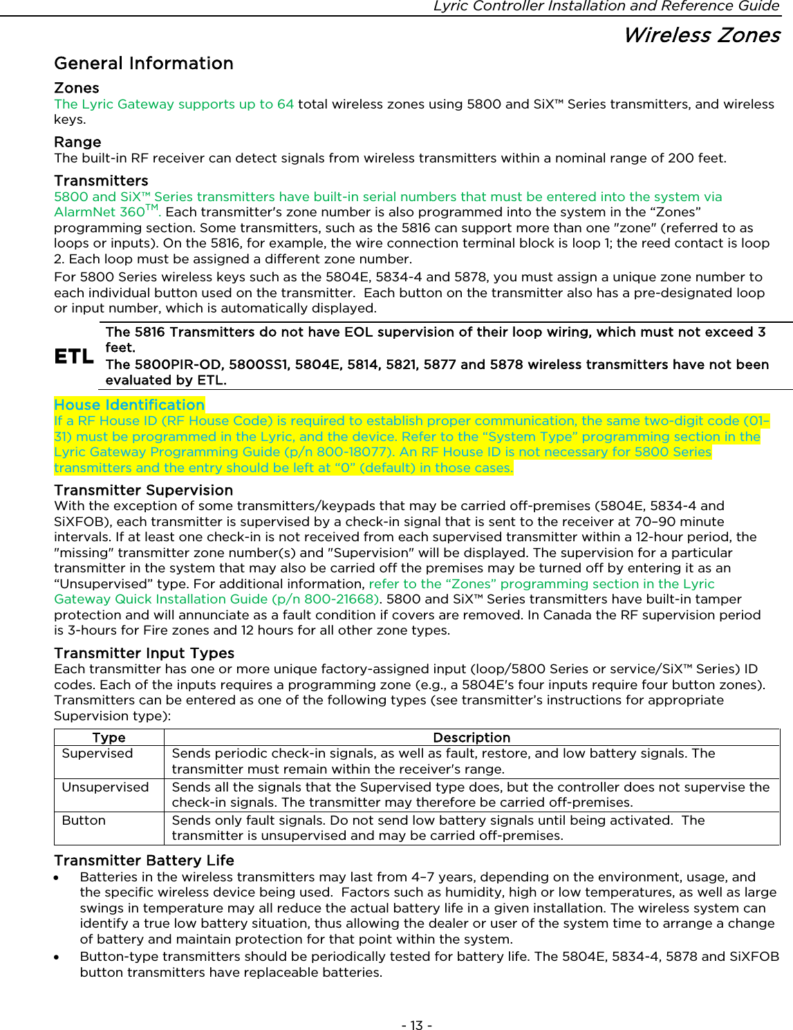
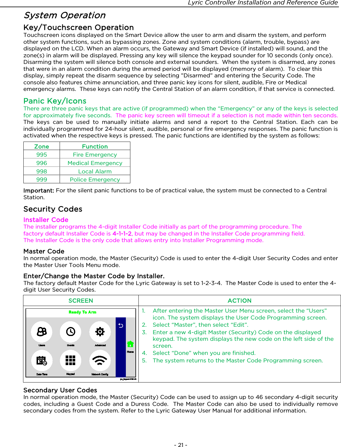
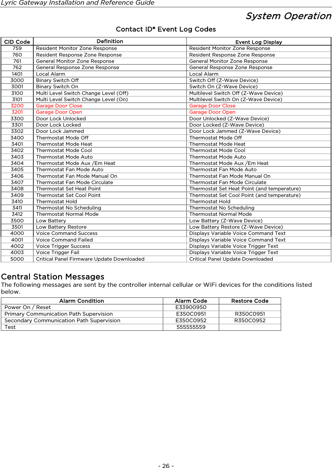
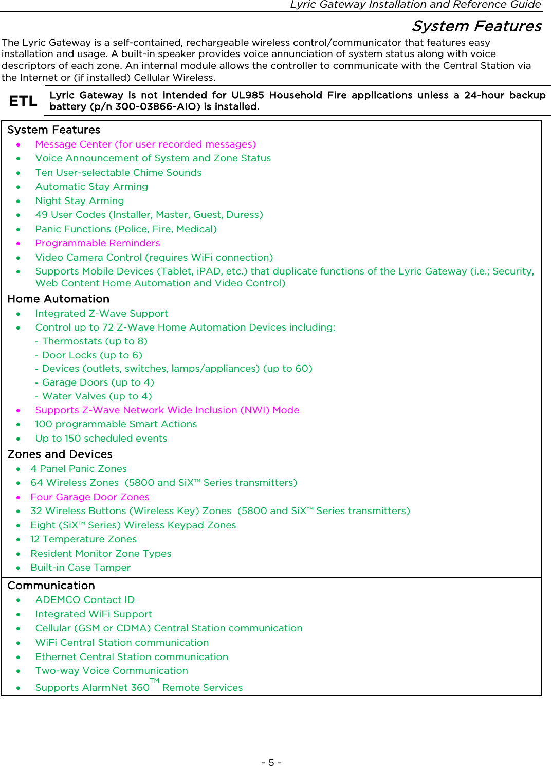
![Lyric Gateway Installation and Reference Guide - 24 - System Operation (Continued) ETL Audio alarm verification has not been evaluated by ETL. Audio Alarm Verification (Two-Way Voice Feature) This feature allows the Central Station operator to listen, talk to or conduct a two-way conversation with an individual(s) at the premises. It also assists the operator in gathering information about the nature and location of the alarm that may be helpful in responding to police and fire departments. All Lyric Controllers are capable of supporting the Two-Way Voice feature. The Lyric Gateway does not make system announcements when the Two-Way Voice feature is active. If a WiFi connection is being used for Two-Way Voice (AAV), sufficient bandwidth must be available. • AAV requires a continuous WiFi upload/download bandwidth of 90kbps for proper operation. • WiFi bandwidth less than 90kbps may result in degraded performance. Activation Fire and CO alarms will prevent the Lyric Gateway from starting an AAV session. A new Fire or CO alarm will end an AAV session that is in progress. The controller sends the “alarm message” followed by a “Listen-in-to-Follow message” (Contact ID® code 606) to the Central Station. The Listen-in-to-Follow message causes the Central Station’s digital receiver to temporarily hold the phone line for approximately 1 minute. When the controller receives the “kissoff” from the Central Station, indicating that the alarm message has been received, the Two-Way Voice (AAV) feature is activated in the (default) “Listen Mode” and sirens and keypad sounds are discontinued. The controller transmits a beep acknowledgment to the Central Station, once per second. The beep alternates between two tones and indicates that the controller is waiting for a session command from the Central Station operator. Once a command is issued the beep acknowledgement is discontinued, however, if a command is not issued within two minutes the system will “time out” and the call will be terminated. Operator Commands The Central Station operator begins the session, which last 5 minutes, by entering one of the valid AAV commands shown in the table below. The session may be extended 5 minutes, without changing the operating mode, by pressing the [7] key on the touch-tone phone. Selecting another operating mode also resets the session an additional 5 minutes. During the last minute of the 5 minute, session, the controller generates two beeps every 30 seconds to alert the Central Station operator that the session is about to time out. The Central Station operator may then extend the session by pressing the [7] key on the touch-tone phone. If the session is not extended, the phone line is disconnected and the session is ended. Sessions may be ended at any time by pressing the [9] key on the touch-tone phone. The AAV modes are described as follows: Note: When entering AAV commands make sure the Central Station receiver has been disconnected from the phone line, otherwise AAV commands may not go through. Key Function 1 Talk Mode: Pressing the [1] key on the touch tone phone, enables one-way voice communication from the Central Sation to the violated premises, and allows the operator to communicate through the controller’s built-in speaker. In this mode the controller’s Panic and Home buttons blink alternately. 2 VOX (Voice) Mode: Pressing the [2] key on the touch-tone phone, enables two-way voice communications between the Central Station and the violated premises via the controller’s built-in speaker and microphone. In this mode the controller’s Panic button is lit Red and the Home button is alternately lit Red and Green. 3 Listen Mode: Pressing the [3] key on the touch-tone phone, Enables one-way audio from the violated premises to the Central Station. The Listen Mode is the start up default mode of the voice feature and allows the operator to listen through the controller microphone. This mode does not affect the existing LED pattern. 7 Extends the session 5 minutes without changing its operating mode. 9 Ends the session and disconnects the phone line.](https://usermanual.wiki/Ademco/8DLGW.Installation-Manual/User-Guide-3152410-Page-24.png)