Ademco 8DLGW Harmony Gateway User Manual Lyric Smart Controller User Guide
Honeywell International Inc. Harmony Gateway Lyric Smart Controller User Guide
UserManual.wiki
>
Ademco
>
8DLGW User Manual
>
Quick User Guide
Contents
1.
Installation Manual
2.
Quick User Guide
Quick User Guide
Navigation menu
Upload a User Manual
Namespaces
Wiki Guide
HTML
PDF
Info
Views
User Manual
Discussion / Help
Navigation
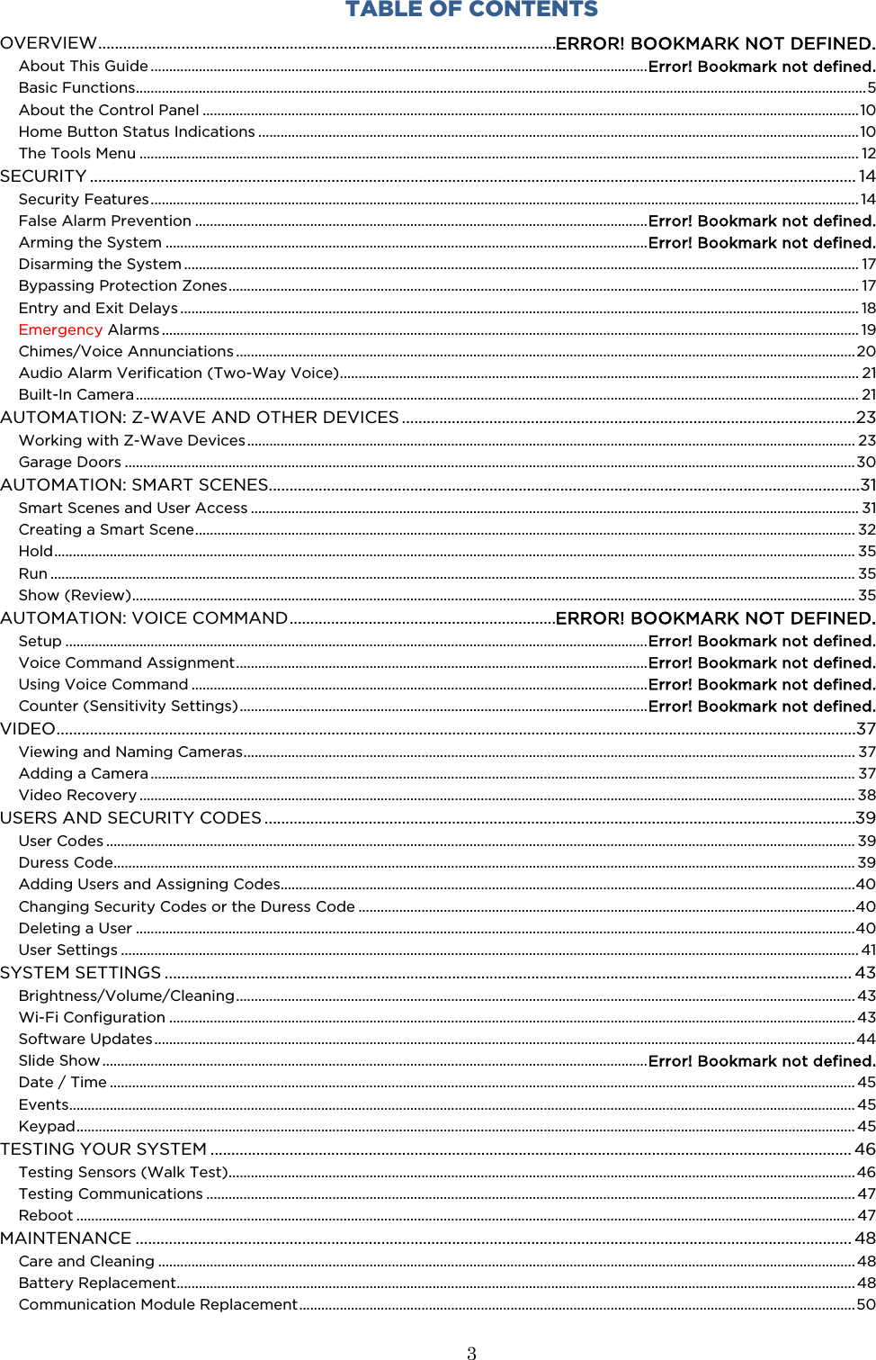
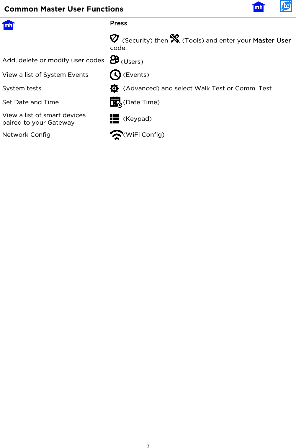
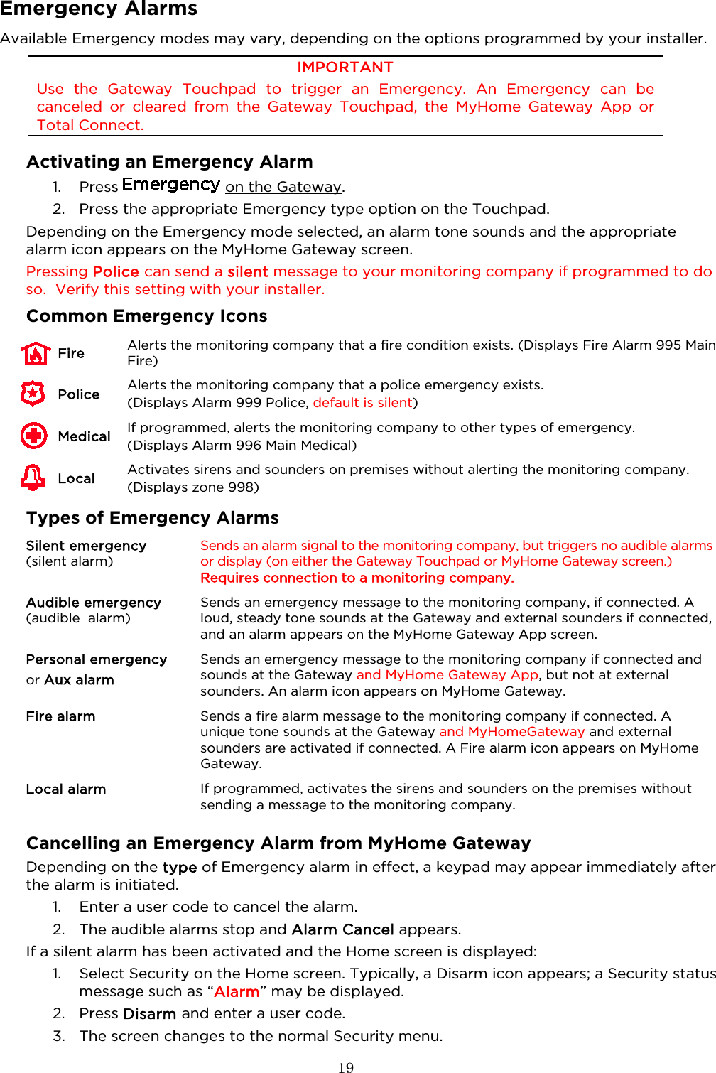
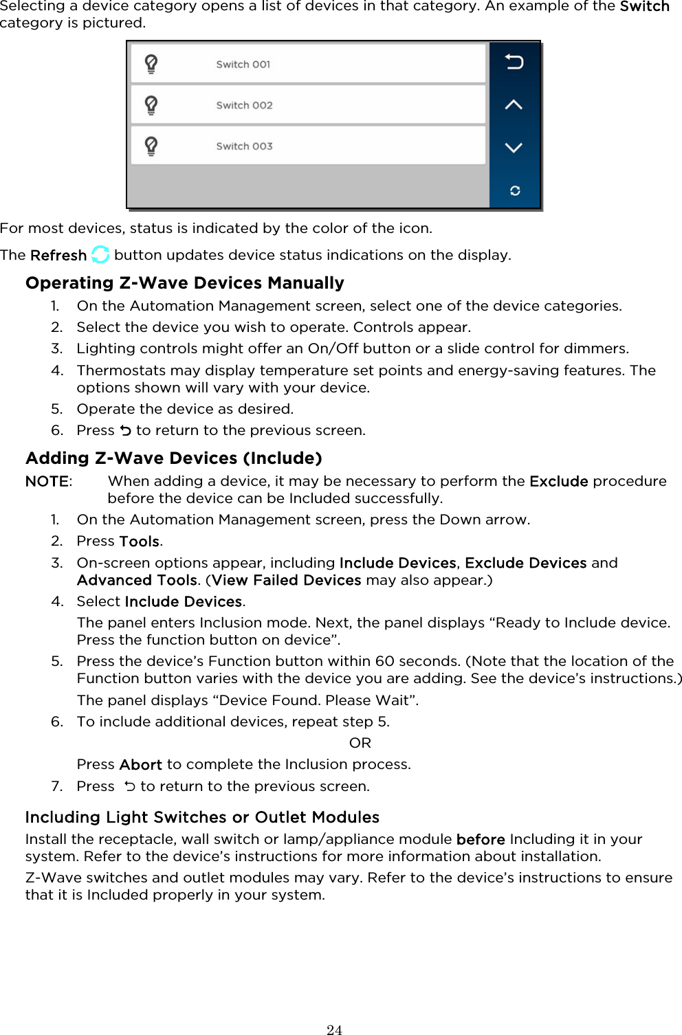
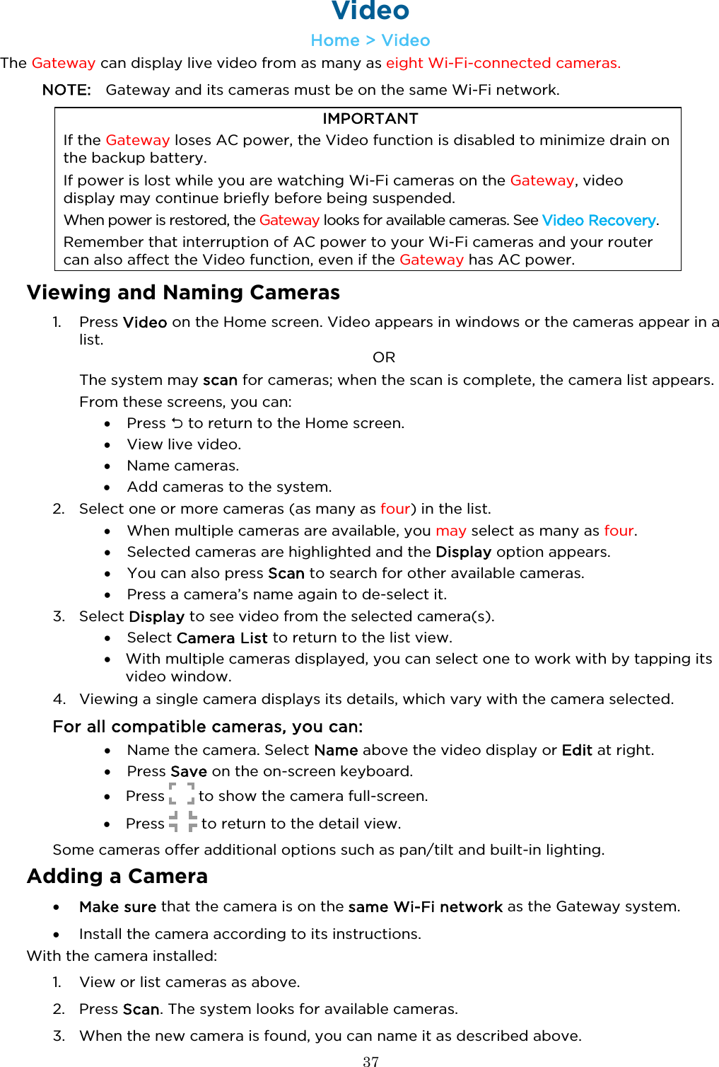
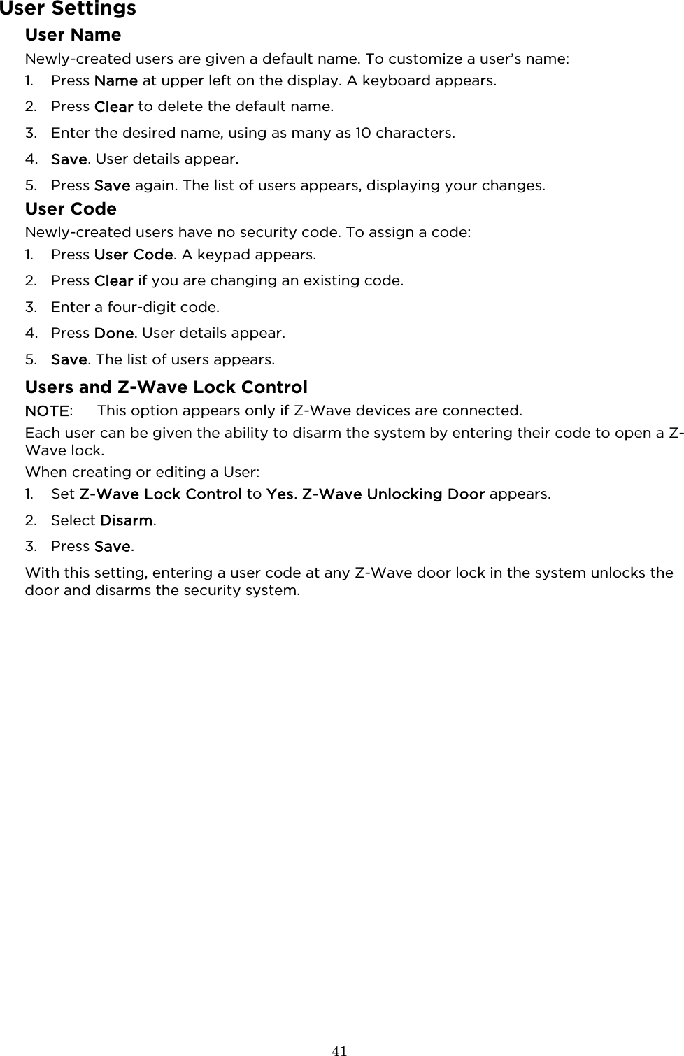
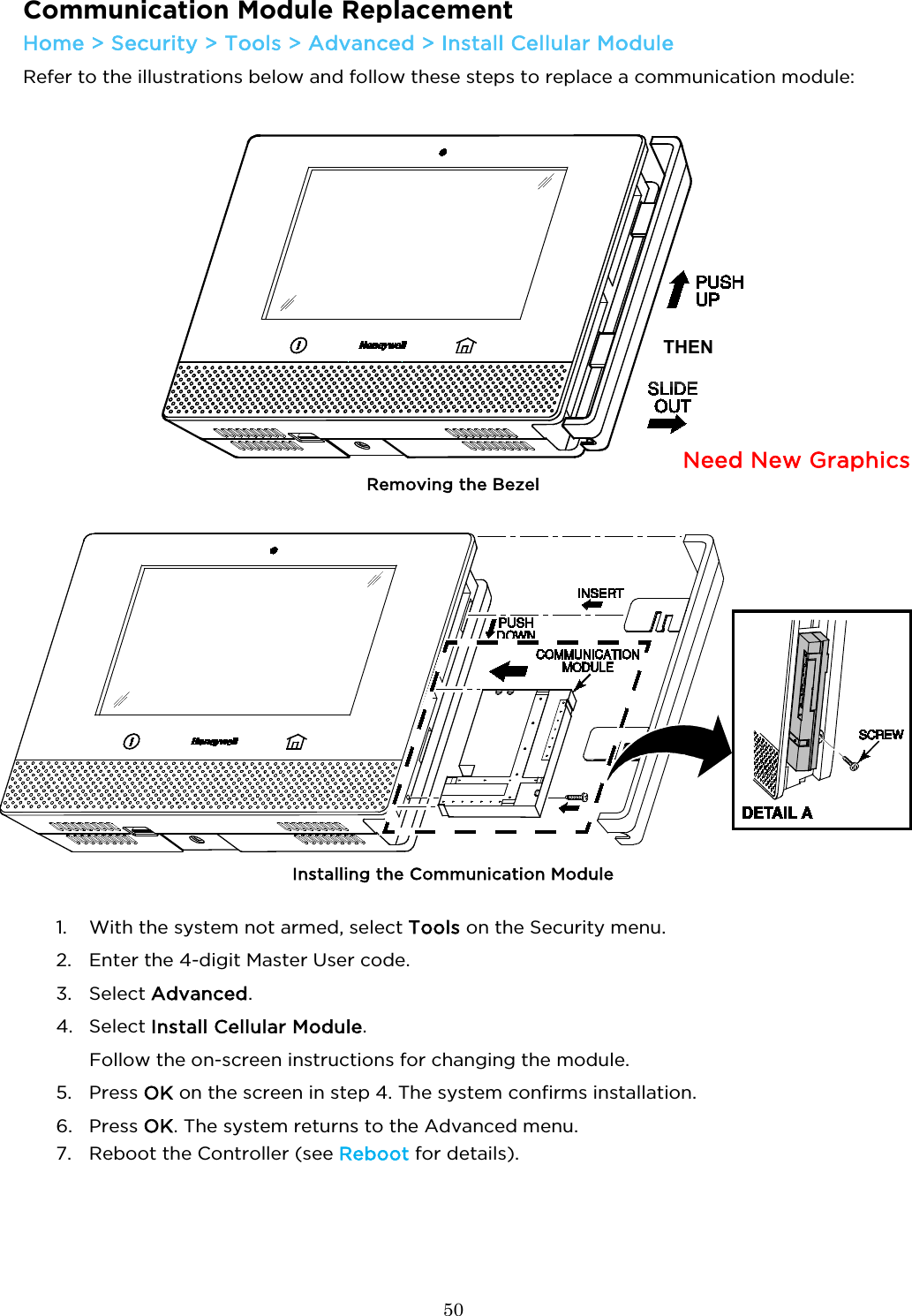
![8 Security Features NOTES: • For the Lyric Gateway to report alarms over the internet, your Wi-Fi network MUST have power at all times. • You must arm your security system in order for it to sound alarms. Sensors and Zones Your system’s sensors are assigned to numbered zones that correspond to areas of your home. For example, the sensor on an entry/exit door might be assigned to Zone 03, a device in a bedroom to Zone 06, and so on. When alarms or trouble conditions occur, you can find information about the zone number and a description of the sensor involved using the MyHome Gateway App. [Home > Security > Tools . Master User Code > Events] Fire Protection Fire protection is always active when the system is operating normally. An alarm sounds if a fire condition is detected. See Fire/CO Alarm System for important information about fire protection, smoke detectors and planning emergency exit routes. Carbon Monoxide Carbon monoxide (CO) detectors, if installed, are always active and sound an alarm if a carbon monoxide condition is detected. See Fire/CO Alarm System for more information. Burglary Protection Gateway provides HOME and AWAY burglary protection. HOME mode protects windows and exterior doors, allowing you to move around inside your home without setting off an alarm. (This mode may be referred to As STAY mode in Total Connect.) AWAY mode protects the entire premises, including interior motion detectors, if present. Both modes offer an entry delay period that allows you to reenter the home without setting off an alarm. For long periods such as vacations, the entry delay can be turned off while arming the system. Gateway also allows you to Bypass selected sensors before arming the system. The system also features Chime mode, which can alert you to the opening of protected doors and windows while the system is disarmed. Security (User) Codes At the time of installation, the installer asks the homeowner to choose a personal 4-digit security code, known as the “Master User code”. Other users can be added, typically with less control over the system than the Master User. See Users and Security Codes. A user code is required when arming or disarming and for some other functions. User Code Error (Keypad Lockout) If “X” invalid user codes are entered, the system locks out additional code entry attempts for a period of time. Additional user code entry attempts will not be accepted until the lock out period ends. NOTE: The system can be Quick Armed while in Lockout mode, but cannot be disarmed. Alarms Alarms are signaled by the internal sounder’s on the Gateway Touchpad and on the smart devices running MyHome Gateway App. (Alarms will also sound on external sirens if used). The Gateway Touchpad’s status shield and Alert blink red; the MyHome Gateway App screen indicates Alarm and shows the zone(s) where the alarm has occurred. After 15 seconds, the sounder stops temporarily and the system begins voice announcements of relevant zone information. After the zones are announced, the panel’s sounder resumes sounding. Alarm sounds and voice announcements alternate until the system is disarmed or until alarm bell timeout occurs. If the system is connected to central monitoring, an alarm message is sent. To silence the sounder, disarm the system. The zone(s) causing the alarm remain displayed on the MyHome Gateway App screen, indicating Memory Of Alarm an Alarm is held in memory. See Clearing an Emergency Alarm for more about clearing memory of alarm. Audio Alarm Verification Allows your central monitoring station to listen to or talk with individual(s) on the premises (if programmed to do so).](https://usermanual.wiki/Ademco/8DLGW.Quick-User-Guide/User-Guide-3152411-Page-8.png)
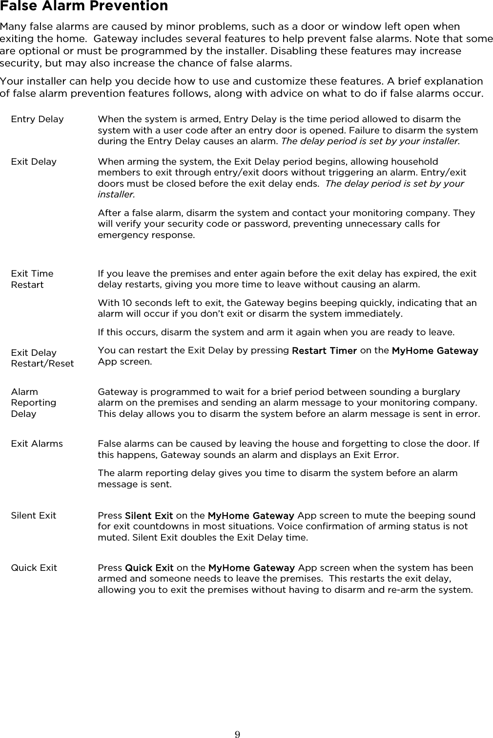
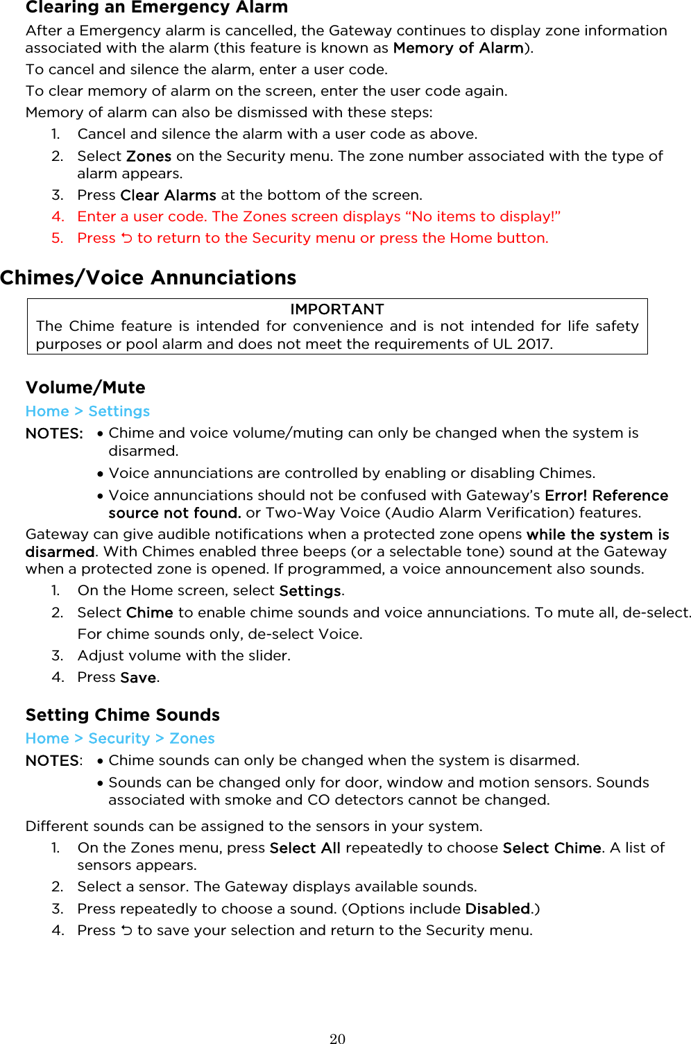
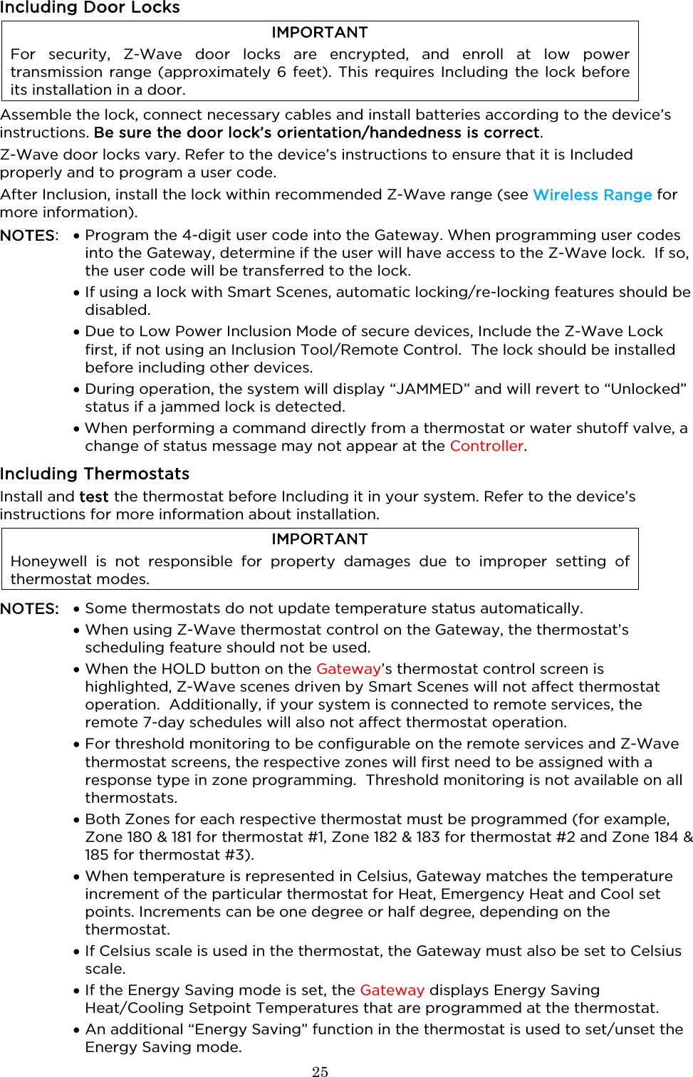
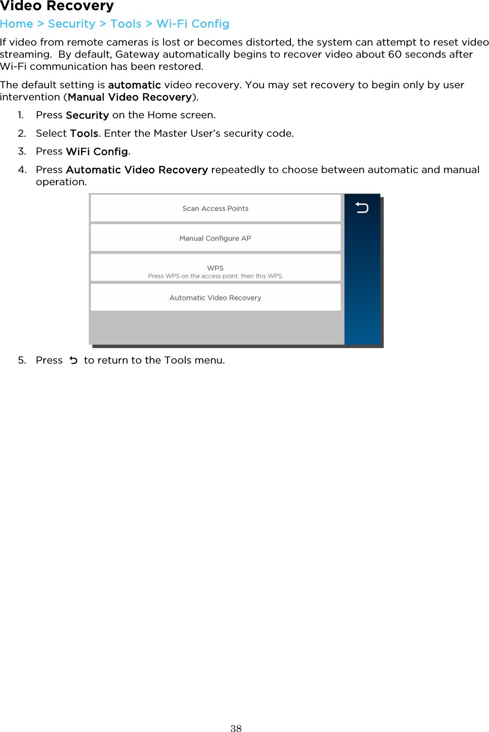
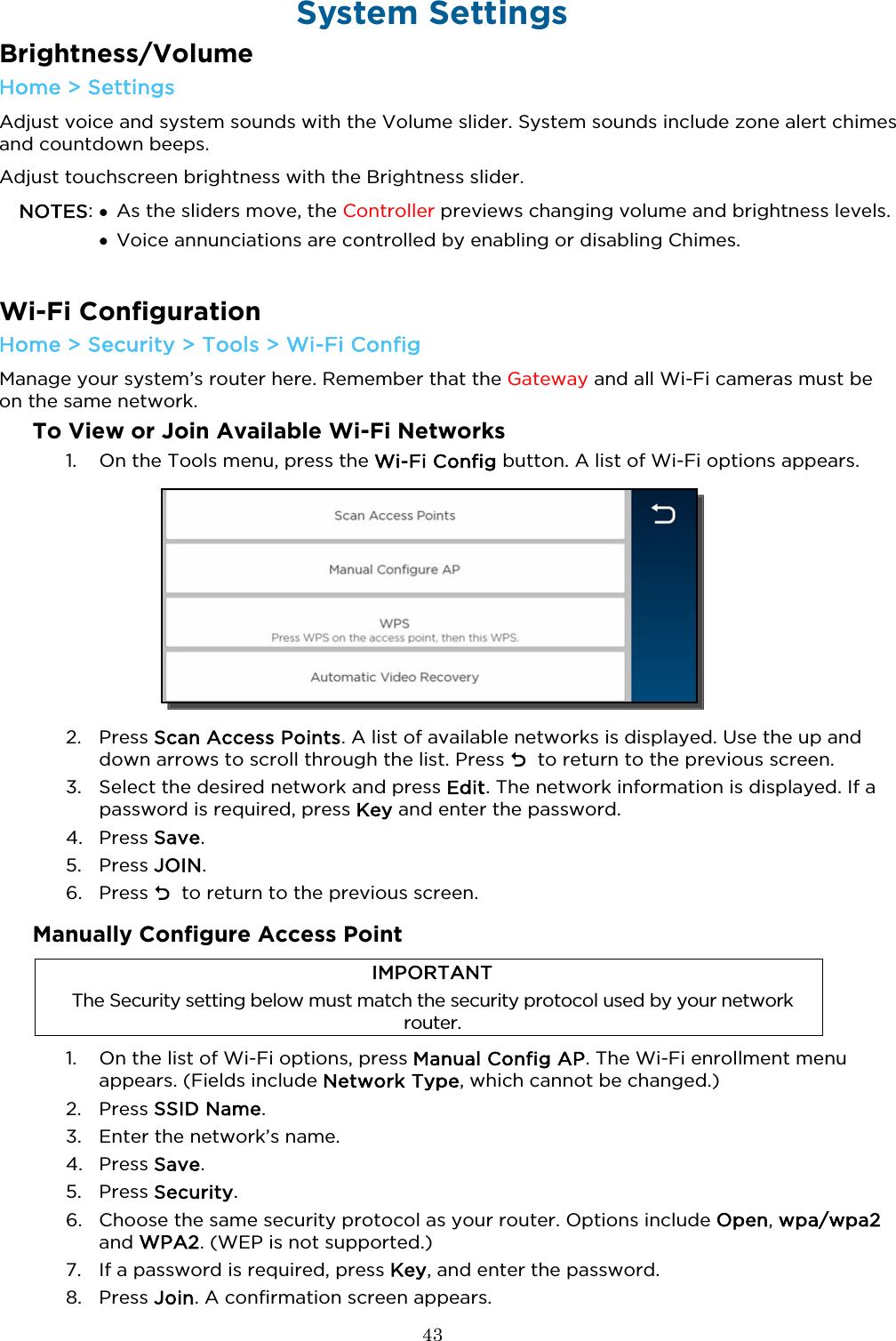
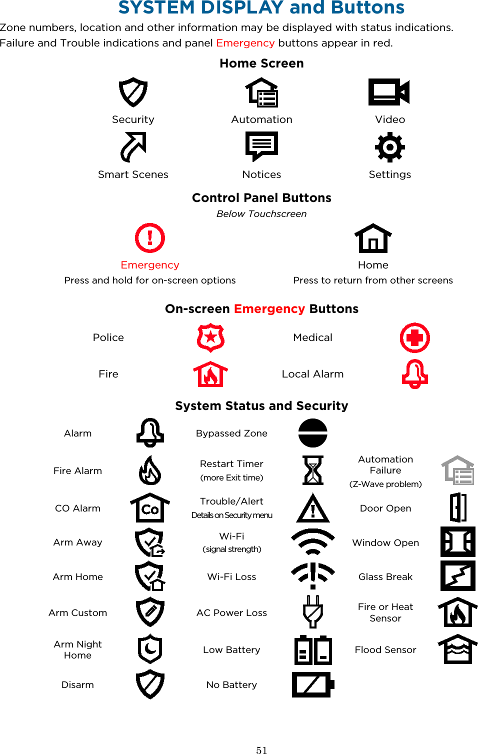
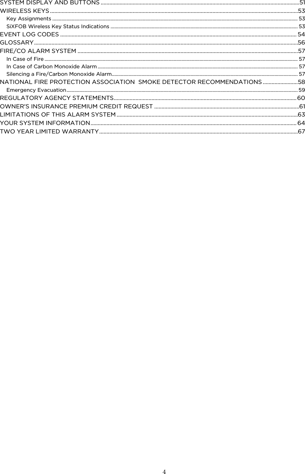
![10 About the Gateway Touchpad The Lyric Gateway Touchpad is designed to operate your basic security features. Also, you can quickly see your system status by which items on the Touchpad are lit. The System Status Shield and arming options are always lit to show system status at a glance. Emergency is also always lit, so it is easy to find, when needed. The other options on the touchpad light only when needed. NOTE: If the Gateway loses AC power, Alert begins to blink slowly after 15 minutes on battery backup and all other lights on the Gateway are off. In this situation, although the Emergency light is off, Emergency functions remain available. System Status Shield Indications The System Status Shield indicates system status with these behaviors: Green, steady System is ready to be armed Green, blinking slowly System is not ready to be armed. Red, steady System is armed Red, blinking slowly Entry delay countdown started; enter your user code to disarm the system Red, blinking rapidly System is in Alarm If programmed to do so, two-way Voice Communication may be active when the system is in Alarm. [See your installer to program this feature.] White, steady System is in user code entry mode See the Emergency section for information on silent alarms.](https://usermanual.wiki/Ademco/8DLGW.Quick-User-Guide/User-Guide-3152411-Page-10.png)
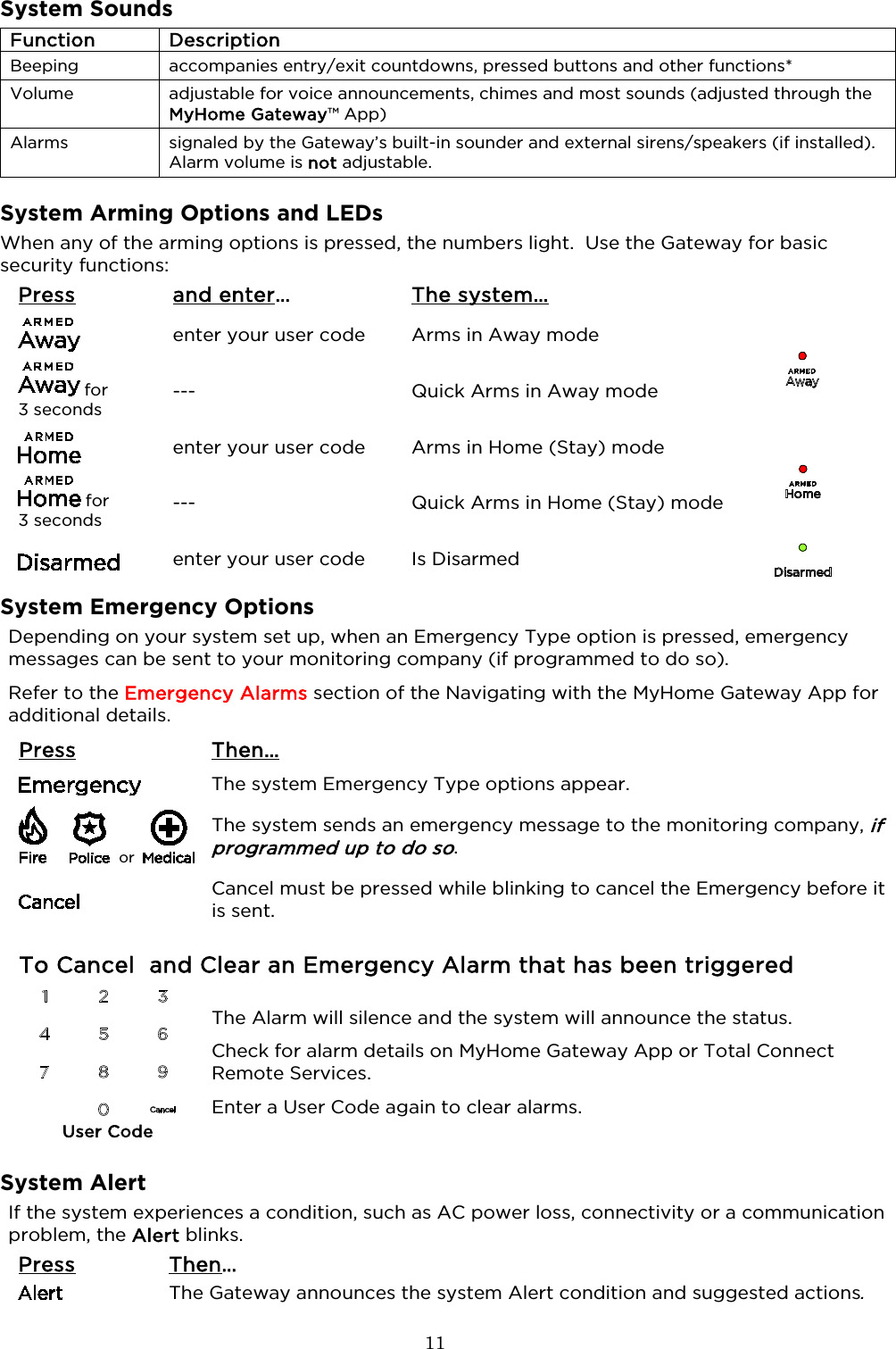
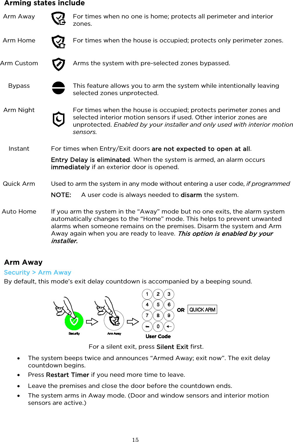
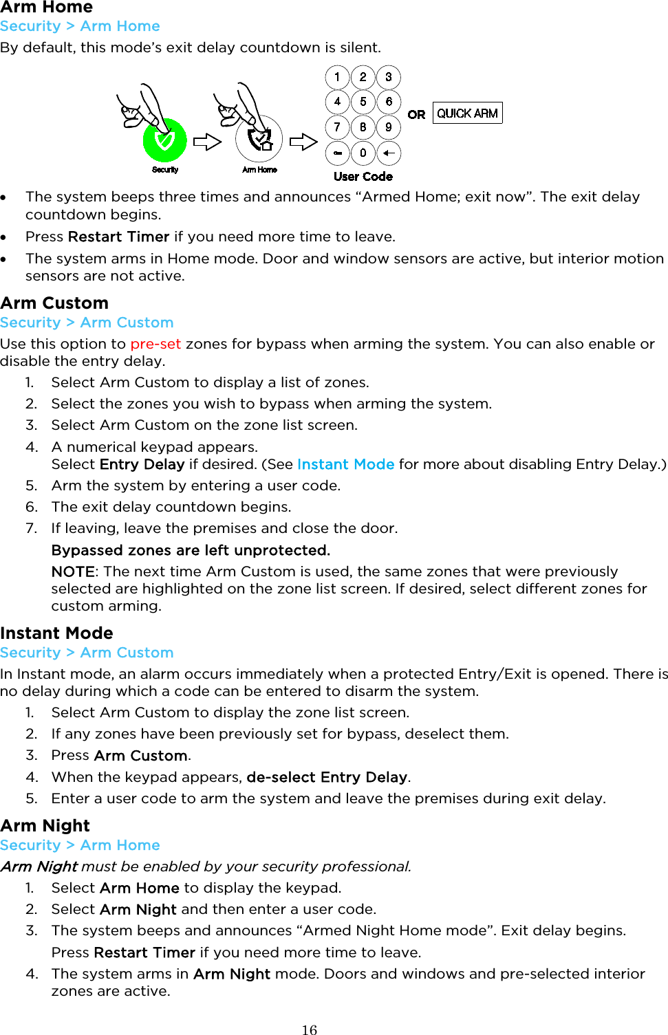
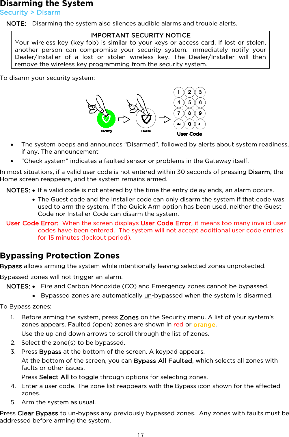
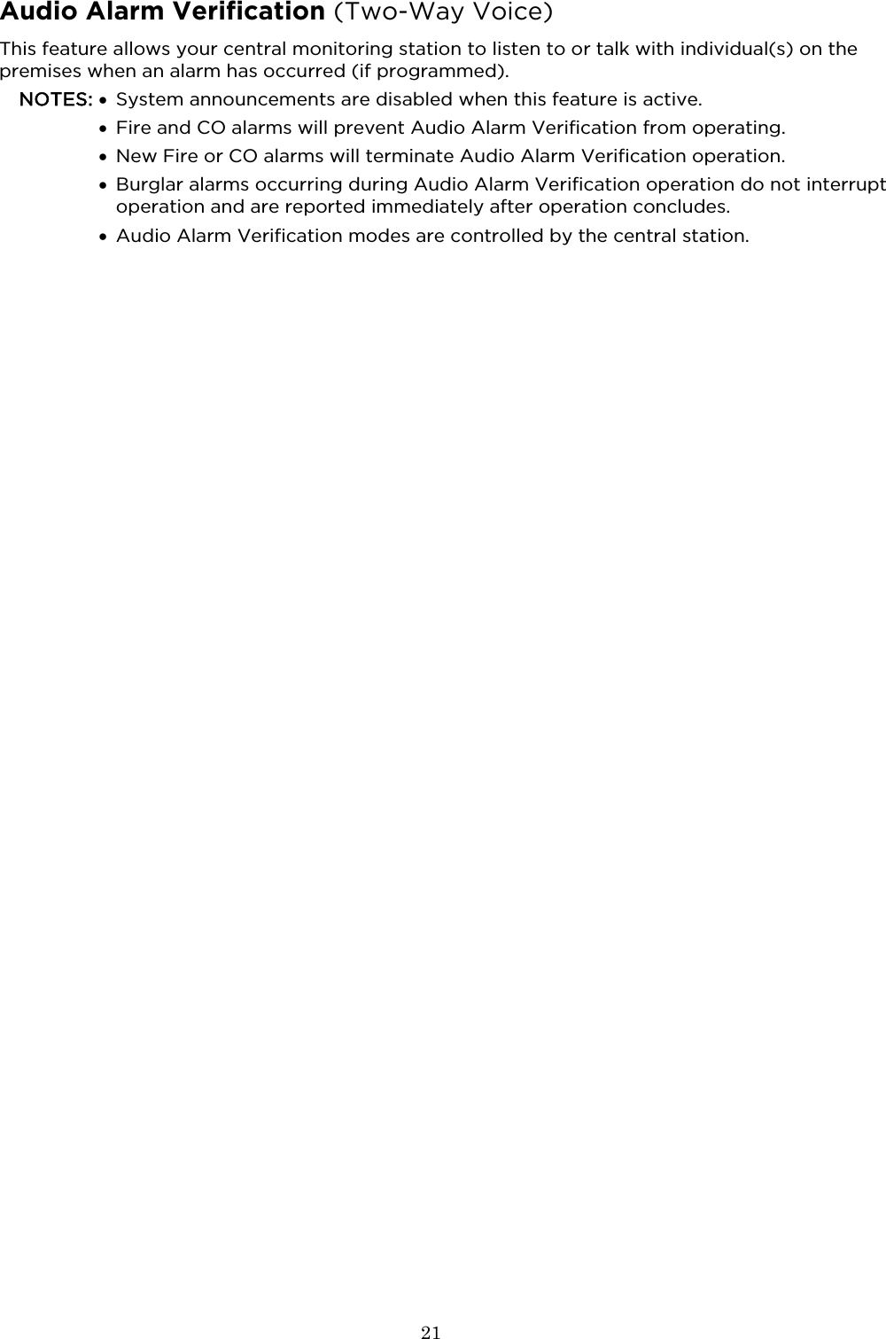
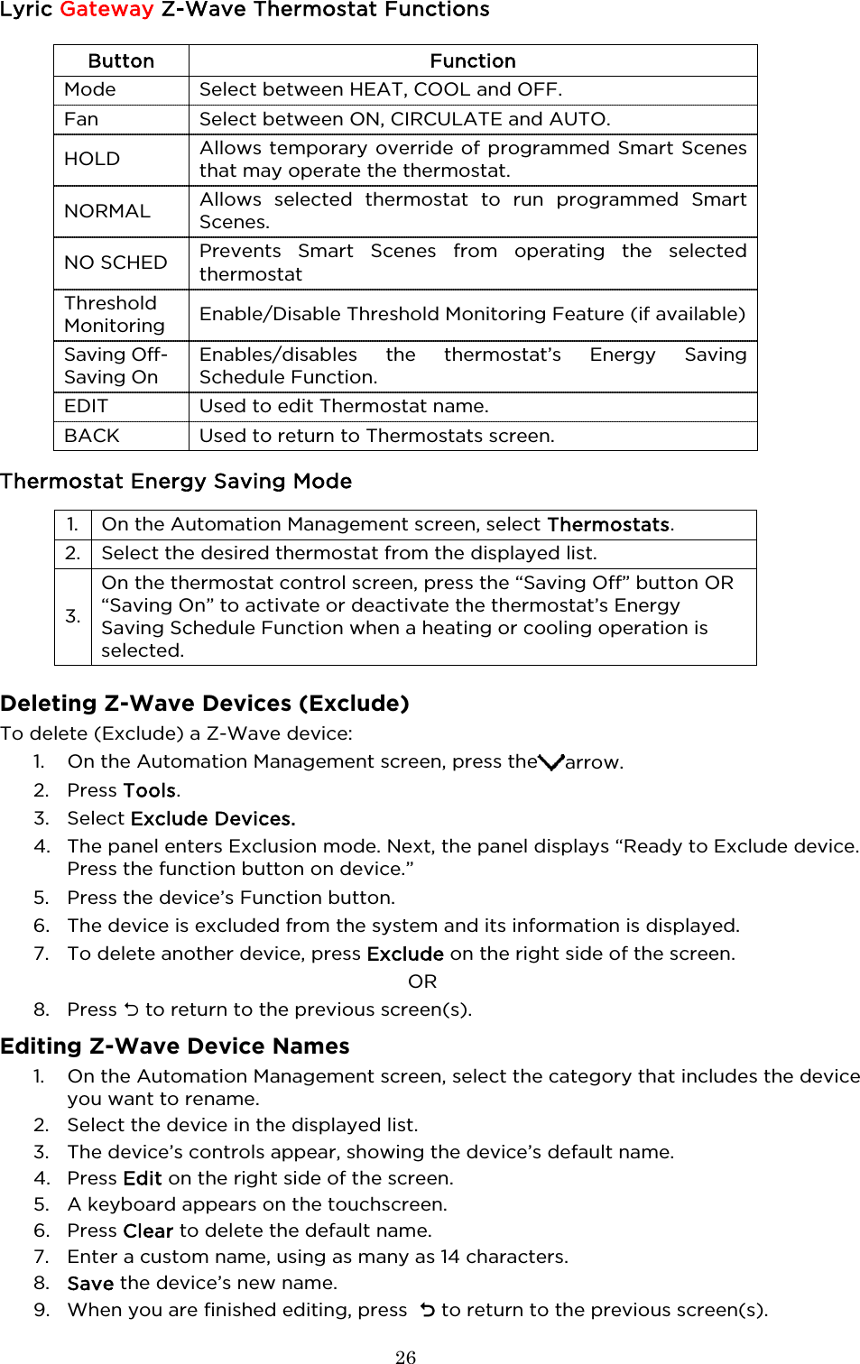
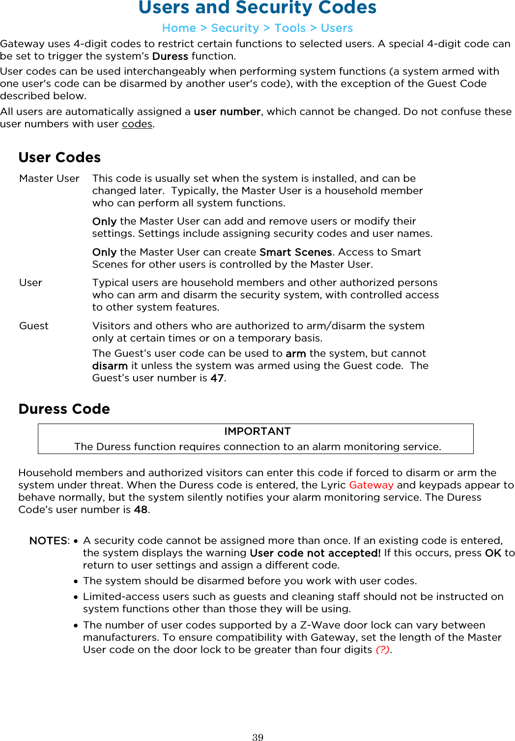
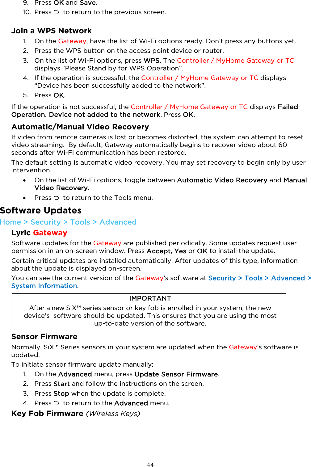
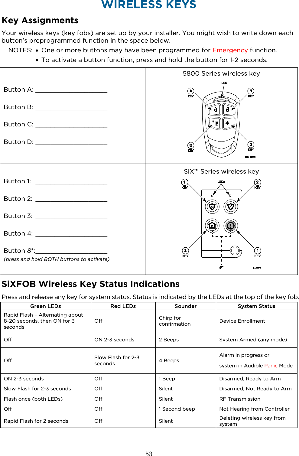
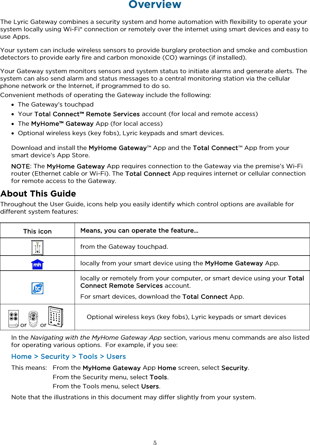
![14 Security Home > Security IMPORTANT If the Gateway is beeping rapidly when you enter the premises, an alarm has occurred and an intruder may still be nearby. LEAVE IMMEDIATELY and CONTACT THE POLICE from a safe location. Security Features NOTES: • For the Lyric Gateway to report alarms over the internet, your Wi-Fi network MUST have power at all times. • You must arm your security system in order for it to sound alarms. Arming the System The MyHome Gateway App displays the system arming status, top and center of the screen: Ready to Arm = the system is ready to be armed. Not Ready To Arm-Fault = one or more zones are faulted. The system cannot be armed until all zone faults are fixed or bypassed. Armed [Home, Away, Custom, etc.] = the system is armed, and arming mode description. Before arming your system, all protected doors, windows, and other protection zones should be closed or bypassed (see Bypassing Protection Zones). To change the volume of countdown sounds and security status voice announcements, see System Settings.](https://usermanual.wiki/Ademco/8DLGW.Quick-User-Guide/User-Guide-3152411-Page-14.png)