Ademco 8DLGW Harmony Gateway User Manual Lyric Smart Controller User Guide
Honeywell International Inc. Harmony Gateway Lyric Smart Controller User Guide
Ademco >
Contents
- 1. Installation Manual
- 2. Quick User Guide
Quick User Guide
User
Reference Guide
Ref: LCP300-L/LCP300-LC
800-21670 10/16 Rev A

Your Honeywell security system is designed for use with devices manufactured or approved by
Honeywell for use with your security system. Your Honeywell security system is not designed for use
with any device that may be attached to your security system's control or other communicating bus
if Honeywell has not approved such device for use with your security system. Use of any such
unauthorized device may cause damage or compromise the performance of your security system
and affect the validity of your Honeywell limited warranty. When you purchase devices that have
been manufactured or approved by Honeywell, you acquire the assurance that these devices have
been thoroughly tested to ensure optimum performance when used with your Honeywell security
system.
Lyric™ Lock
Your system supports advanced features designed to keep it functioning optimally. These
capabilities include: the ability to interact with Honeywell and your dealer’s network for the setup
and programming of its features, support for remote software updates and the ability (when enabled
by your monitoring dealer) to enhance your security by preventing an unauthorized takeover of the
system by another monitoring company. In the event that your dealer has enabled the feature to
prevent an unauthorized takeover and you wish to authorize a new company to take over your
system, you may request that Honeywell remotely disable this feature. Honeywell will require
documentation that you have attempted to contact your existing security dealer and that they have
failed to respond, or failed to agree to your request.
3
TABLE OF CONTENTS
OVERVIEW ..............................................................................................................ERROR! BOOKMARK NOT DEFINED.
About This Guide ...................................................................................................................................... Error! Bookmark not defined.
Basic Functions ..................................................................................................................................................................................................... 5
About the Control Panel ................................................................................................................................................................................. 10
Home Button Status Indications .................................................................................................................................................................. 10
The Tools Menu .................................................................................................................................................................................................. 12
SECURITY ........................................................................................................................................................................................ 14
Security Features ............................................................................................................................................................................................... 14
False Alarm Prevention .......................................................................................................................... Error! Bookmark not defined.
Arming the System .................................................................................................................................. Error! Bookmark not defined.
Disarming the System ...................................................................................................................................................................................... 17
Bypassing Protection Zones .......................................................................................................................................................................... 17
Entry and Exit Delays ....................................................................................................................................................................................... 18
Emergency Alarms ............................................................................................................................................................................................ 19
Chimes/Voice Annunciations ....................................................................................................................................................................... 20
Audio Alarm Verification (Two-Way Voice) ............................................................................................................................................ 21
Built-In Camera ................................................................................................................................................................................................... 21
AUTOMATION: Z-WAVE AND OTHER DEVICES ............................................................................................................. 23
Working with Z-Wave Devices .................................................................................................................................................................... 23
Garage Doors ..................................................................................................................................................................................................... 30
AUTOMATION: SMART SCENES.............................................................................................................................................. 31
Smart Scenes and User Access .................................................................................................................................................................... 31
Creating a Smart Scene .................................................................................................................................................................................. 32
Hold ........................................................................................................................................................................................................................ 35
Run ......................................................................................................................................................................................................................... 35
Show (Review) ................................................................................................................................................................................................... 35
AUTOMATION: VOICE COMMAND ................................................................ERROR! BOOKMARK NOT DEFINED.
Setup ............................................................................................................................................................. Error! Bookmark not defined.
Voice Command Assignment ............................................................................................................... Error! Bookmark not defined.
Using Voice Command ........................................................................................................................... Error! Bookmark not defined.
Counter (Sensitivity Settings) .............................................................................................................. Error! Bookmark not defined.
VIDEO ................................................................................................................................................................................................ 37
Viewing and Naming Cameras ..................................................................................................................................................................... 37
Adding a Camera .............................................................................................................................................................................................. 37
Video Recovery ................................................................................................................................................................................................. 38
USERS AND SECURITY CODES .............................................................................................................................................. 39
User Codes .......................................................................................................................................................................................................... 39
Duress Code ........................................................................................................................................................................................................ 39
Adding Users and Assigning Codes........................................................................................................................................................... 40
Changing Security Codes or the Duress Code ...................................................................................................................................... 40
Deleting a User .................................................................................................................................................................................................. 40
User Settings ....................................................................................................................................................................................................... 41
SYSTEM SETTINGS ..................................................................................................................................................................... 43
Brightness/Volume/Cleaning ....................................................................................................................................................................... 43
Wi-Fi Configuration ......................................................................................................................................................................................... 43
Software Updates ............................................................................................................................................................................................. 44
Slide Show ................................................................................................................................................... Error! Bookmark not defined.
Date / Time ......................................................................................................................................................................................................... 45
Events .................................................................................................................................................................................................................... 45
Keypad .................................................................................................................................................................................................................. 45
TESTING YOUR SYSTEM .......................................................................................................................................................... 46
Testing Sensors (Walk Test) ......................................................................................................................................................................... 46
Testing Communications ............................................................................................................................................................................... 47
Reboot .................................................................................................................................................................................................................. 47
MAINTENANCE ............................................................................................................................................................................ 48
Care and Cleaning ............................................................................................................................................................................................ 48
Battery Replacement ....................................................................................................................................................................................... 48
Communication Module Replacement ...................................................................................................................................................... 50
4
SYSTEM DISPLAY AND BUTTONS ......................................................................................................................................... 51
WIRELESS KEYS ........................................................................................................................................................................... 53
Key Assignments .............................................................................................................................................................................................. 53
SiXFOB Wireless Key Status Indications ................................................................................................................................................. 53
EVENT LOG CODES ................................................................................................................................................................... 54
GLOSSARY ...................................................................................................................................................................................... 56
FIRE/CO ALARM SYSTEM ........................................................................................................................................................ 57
In Case of Fire .................................................................................................................................................................................................... 57
In Case of Carbon Monoxide Alarm ........................................................................................................................................................... 57
Silencing a Fire/Carbon Monoxide Alarm ................................................................................................................................................ 57
NATIONAL FIRE PROTECTION ASSOCIATION SMOKE DETECTOR RECOMMENDATIONS ........................ 58
Emergency Evacuation ................................................................................................................................................................................... 59
REGULATORY AGENCY STATEMENTS .............................................................................................................................. 60
OWNER'S INSURANCE PREMIUM CREDIT REQUEST .................................................................................................... 61
LIMITATIONS OF THIS ALARM SYSTEM ............................................................................................................................. 63
YOUR SYSTEM INFORMATION .............................................................................................................................................. 64
TWO YEAR LIMITED WARRANTY ......................................................................................................................................... 67
5
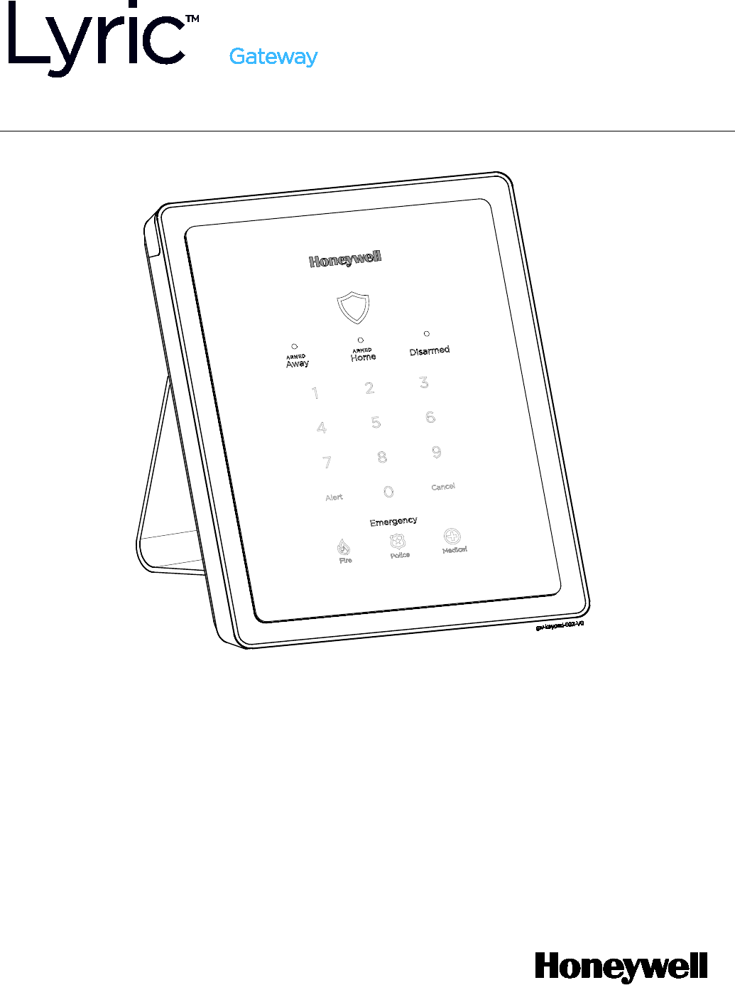
Overview
The Lyric Gateway combines a security system and home automation with flexibility to operate your
system locally using Wi-Fi® connection or remotely over the internet using smart devices and easy to
use Apps.
Your system can include wireless sensors to provide burglary protection and smoke and combustion
detectors to provide early fire and carbon monoxide (CO) warnings (if installed).
Your Gateway system monitors sensors and system status to initiate alarms and generate alerts. The
system can also send alarm and status messages to a central monitoring station via the cellular
phone network or the Internet, if programmed to do so.
Convenient methods of operating the Gateway include the following:
• The Gateway’s touchpad
• Your Total Connect™ Remote Services account (for local and remote access)
• The MyHome™ Gateway App (for local access)
• Optional wireless keys (key fobs), Lyric keypads and smart devices.
Download and install the MyHome Gateway™ App and the Total Connect™ App from your
smart device’s App Store.
NOTE: The MyHome Gateway App requires connection to the Gateway via the premise’s Wi-Fi
router (Ethernet cable or Wi-Fi). The Total Connect App requires internet or cellular connection
for remote access to the Gateway.
About This Guide
Throughout the User Guide, icons help you easily identify which control options are available for
different system features:
This icon
Means, you can operate the feature…
from the Gateway touchpad.
locally from your smart device using the
MyHome Gateway
App.
locally or remotely from your computer, or smart device using your
Total
Connect
Remote Services
account.
For smart devices, download the
Total Connect
App.
or or
Optional wireless keys (key fobs), Lyric keypads or smart devices
In the Navigating with the MyHome Gateway App section, various menu commands are also listed
for operating various options. For example, if you see:
Home > Security > Tools > Users
This means: From the MyHome Gateway App Home screen, select Security.
From the Security menu, select Tools.
From the Tools menu, select Users.
Note that the illustrations in this document may differ slightly from your system.
6
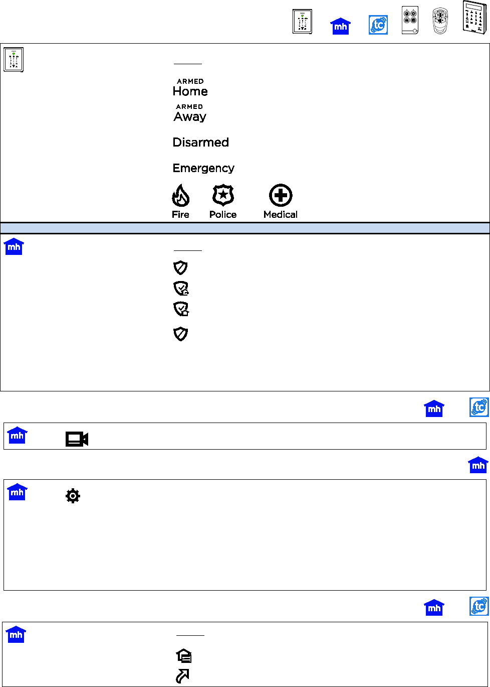
Basic System Functions
Security
Press
Arm
in Home mode
and enter
your user code
Arm
in Away mode
and enter
your user code
Disarm
system &
silence
alarms
and enter your user code. Repeat to silence
alarms/alerts
Emergency
Then press:
or
notifies the monitoring company
of the emergency type (if
programmed to do so)
Press
Access Security features
on the Home screen
Arm
in Away mode
and enter your user code
Arm
in Home mode
and enter your user code
Disarm
system &
silence
alarms
and enter yo
ur user code. Repeat to silence
alarms/alerts
Emergency (Panic)
Use the Gateway Touchpad Emergency
options or, if
programmed to do so, use your wireless key (key fob) to
signal an emergency.
Video
Press on the Home screen to view and configure Wi-Fi cameras
Control Panel Settings
Press (Settings) on the Home screen
Gateway key brightness
Select Brightness
and use the slider
Gateway volume
Select Volume
and use the slider
Voice announcements volume
Select
or deselect
VOICE
Chime volume (count-down beeps,
other sounds)
Select
or deselect
CHIME
Automation Features
Press
Operate & manage Z-Wave® devices
on the Home screen
Create & manage Smart Scenes
on the Home screen
7
Common Master User Functions
Press
(Security) then , (Tools) and enter your
Master User
code.
Add, delete or modify user codes (Users)
View a list of System Events
(Events)
System tests
(Advanced) and select Walk Test or Comm. Test
Set Date and Time
(Date Time)
View a list of smart devices
paired to your Gateway
(Keypad)
Network Config
(WiFi Config)

8
Security Features
NOTES: • For the Lyric Gateway to report alarms over the internet, your Wi-Fi network MUST
have power at all times.
• You must arm your security system in order for it to sound alarms.
Sensors and
Zones
Your system’s sensors are assigned to numbered
zones
that correspond to areas of
your home. For example, the sensor on an entry/exit door might be assigned to Zone
03, a device in a bedroom to Zone 06, and so on.
When alarms or trouble conditions occur, you can find information about the zone
number and a description of the sensor involved using the MyHome Gateway App.
[
Home > Security > Tools . Master User Code > Events
]
Fire
Protection
Fire protection is always active when the system is operating normally. An alarm
sounds if a fire condition is detected. See
Fire/CO Alarm System
for important
information about fire protection, smoke detectors and planning emergency exit
routes.
Carbon
Monoxide
Carbon monoxide (CO) detectors, if installed, are always active and sound an alarm if a
carbon monoxide condition is detected. See
Fire/CO Alarm System
for more information.
Burglary
Protection
Gateway provides HOME and AWAY burglary protection.
HOME mode protects windows and exterior doors, allowing you to move around inside
your home without setting off an alarm. (This mode may be referred to As STAY mode
in Total Connect.)
AWAY mode protects the entire premises, including interior motion detectors, if
present.
Both modes offer an entry delay period that allows you to reenter the home without
setting off an alarm. For long periods such as vacations, the entry delay can be turned
off while arming the system.
Gateway also allows you to
Bypass
selected sensors before arming the system.
The system also features
Chime
mode, which can alert you to the opening of protected
doors and windows while the system is disarmed.
Security
(User)
Codes
At the time of installation, the installer asks the homeowner to choose a personal
4-digit security code, known as the “Master User code”.
Other users can be added, typically with less control over the system than the Master
User. See
Users and Security Codes
.
A user code is required when arming or disarming and for some other functions.
User Code
Error
(Keypad
Lockout)
If “X” invalid user codes are entered, the system locks out additional code entry
attempts for a period of time. Additional user code entry attempts will not be
accepted until the lock out period ends.
NOTE
: The system can be Quick Armed while in Lockout mode, but cannot be
disarmed.
Alarms Alarms are signaled by the internal sounder’s on the
Gateway Touchpad
and on the smart
devices running
MyHome Gateway
App. (Alarms will also sound on external sirens if used).
The Gateway Touchpad’s status shield and
Alert
blink red; the MyHome Gateway App
screen indicates
Alarm
and shows the zone(s) where the alarm has occurred. After 15
seconds, the sounder stops temporarily and the system begins voice announcements of
relevant zone information.
After the zones are announced, the panel’s sounder resumes sounding. Alarm sounds
and voice announcements alternate until the system is disarmed or until alarm bell
timeout occurs. If the system is connected to central monitoring, an alarm message is
sent.
To silence the sounder, disarm the system
. The zone(s) causing the alarm remain
displayed on the MyHome Gateway App screen, indicating Memory Of Alarm an Alarm is
held in memory. See
Clearing an Emergency Alarm
for more about clearing memory
of alarm.
Audio Alarm
Verification
Allows your central monitoring station to listen to or talk with individual(s) on the
premises (if programmed to do so).
9
False Alarm Prevention
Many false alarms are caused by minor problems, such as a door or window left open when
exiting the home. Gateway includes several features to help prevent false alarms. Note that some
are optional or must be programmed by the installer. Disabling these features may increase
security, but may also increase the chance of false alarms.
Your installer can help you decide how to use and customize these features. A brief explanation
of false alarm prevention features follows, along with advice on what to do if false alarms occur.
Entry Delay
When the system is armed, Entry Delay is the time period allowed to disarm the
system with a user code after an entry door is opened. Failure to disarm the system
during the Entry Delay causes an alarm. The delay period is set by your installer.
Exit Delay When arming the system, the Exit Delay period begins, allowing household
members to exit through entry/exit doors without triggering an alarm. Entry/exit
doors must be closed before the exit delay ends. The delay period is set by your
installer.
After a false alarm, disarm the system and contact your monitoring company. They
will verify your security code or password, preventing unnecessary calls for
emergency response.
Exit Time
Restart
Exit Delay
Restart/Reset
If you leave the premises and enter again before the exit delay has expired, the exit
delay restarts, giving you more time to leave without causing an alarm.
With 10 seconds left to exit, the Gateway begins beeping quickly, indicating that an
alarm will occur if you don’t exit or disarm the system immediately.
If this occurs, disarm the system and arm it again when you are ready to leave.
You can restart the Exit Delay by pressing
Restart Timer
on the
MyHome Gateway
App screen.
Alarm
Reporting
Delay
Gateway is programmed to wait for a brief period between sounding a burglary
alarm on the premises and sending an alarm message to your monitoring company.
This delay allows you to disarm the system before an alarm message is sent in error.
Exit Alarms False alarms can be caused by leaving the house and forgetting to close the door. If
this happens, Gateway sounds an alarm and displays an Exit Error.
The alarm reporting delay gives you time to disarm the system before an alarm
message is sent.
Silent Exit Press
Silent Exit
on the
MyHome Gateway
App screen to mute the beeping sound
for exit countdowns in most situations. Voice confirmation of arming status is not
muted. Silent Exit doubles the Exit Delay time.
Quick Exit Press
Quick Exit
on the
MyHome Gateway
App screen when the system has been
armed and someone needs to leave the premises. This restarts the exit delay,
allowing you to exit the premises without having to disarm and re-arm the system.
10
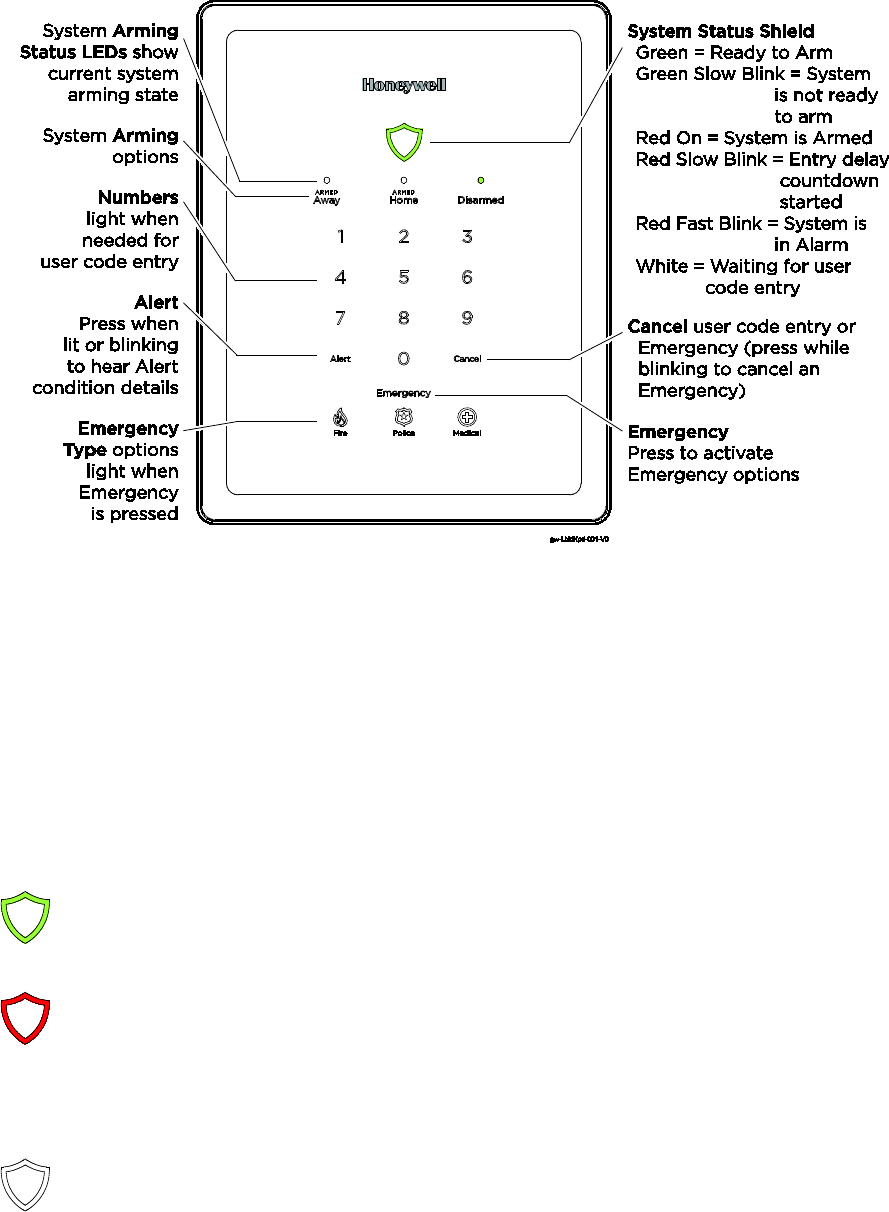
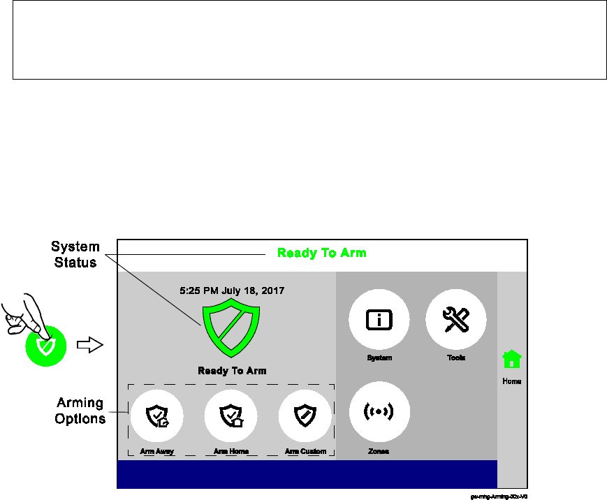
About the Gateway Touchpad
The Lyric Gateway Touchpad is designed to operate your basic security features. Also, you can
quickly see your system status by which items on the Touchpad are lit.
The System Status Shield and arming options are always lit to show system status at a glance.
Emergency is also always lit, so it is easy to find, when needed. The other options on the
touchpad light only when needed.
NOTE: If the Gateway loses AC power, Alert begins to blink slowly after 15 minutes on
battery backup and all other lights on the Gateway are off. In this situation, although
the Emergency light is off, Emergency functions remain available.
System Status Shield Indications
The System Status Shield indicates system status with these behaviors:
Green, steady
System is ready to be armed
Green, blinking
slowly
System is not ready to be armed.
Red, steady
System is armed
Red, blinking slowly
Entry delay countdown started; enter your user code to
disarm the system
Red, blinking rapidly
System is in Alarm
If programmed to do so, two-way Voice Communication
may be active when the system is in Alarm. [See your
installer to program this feature.]
White, steady
System is in user code entry mode
See the Emergency section for information on silent alarms.
11
System Sounds
Function
Description
Beeping accompanies entry/exit countdowns, pressed buttons and other functions*
Volume adjustable for voice announcements, chimes and most sounds (adjusted through the
MyHome Gateway
™ App)
Alarms signaled by the Gateway’s built-in sounder and external sirens/speakers (if installed).
Alarm volume is
not
adjustable.
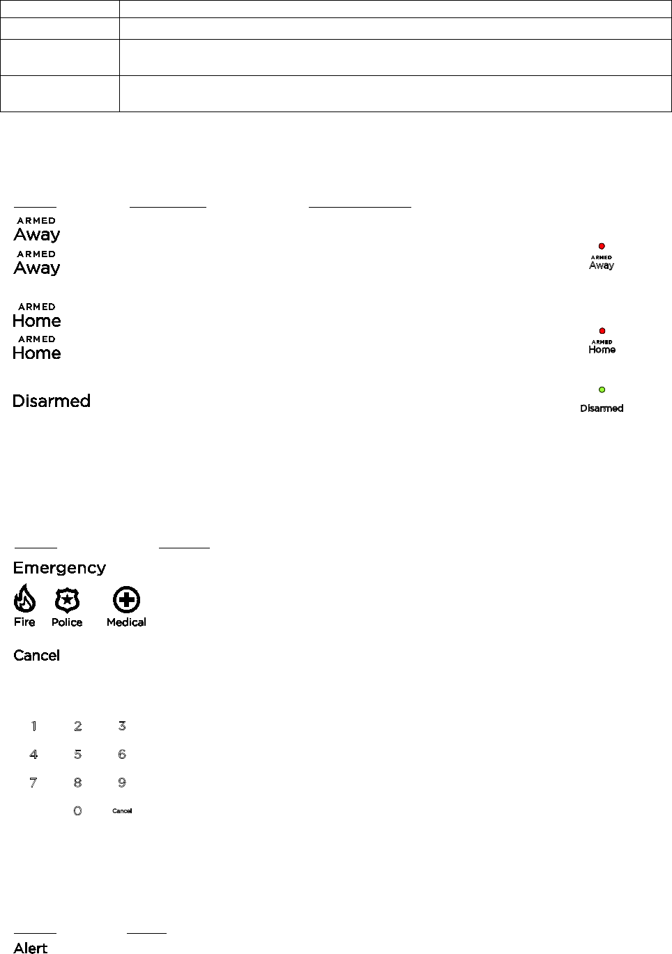
System Arming Options and LEDs
When any of the arming options is pressed, the numbers light. Use the Gateway for basic
security functions:
Press
and enter…
The system…
enter your user code Arms in Away mode
for
3 seconds
--- Quick Arms in Away mode
enter your user code Arms in Home (Stay) mode
for
3 seconds
--- Quick Arms in Home (Stay) mode
enter your user code Is Disarmed
System Emergency Options
Depending on your system set up, when an Emergency Type option is pressed, emergency
messages can be sent to your monitoring company (if programmed to do so).
Refer to the Emergency Alarms section of the Navigating with the MyHome Gateway App for
additional details.
Press
Then…
The system Emergency Type options appear.
or
The system sends an emergency message to the monitoring company,
if
programmed up to do so
.
Cancel must be pressed while blinking to cancel the Emergency before it
is sent.
To Cancel and Clear an Emergency Alarm that has been triggered
User Code
The Alarm will silence and the system will announce the status.
Check for alarm details on MyHome Gateway App or Total Connect
Remote Services.
Enter a User Code again to clear alarms.
System Alert
If the system experiences a condition, such as AC power loss, connectivity or a communication
problem, the Alert blinks.
Press
Then…
The Gateway announces the system Alert condition and suggested actions.
12
Software Update Notifications
Software updates for the Gateway are published periodically. Certain critical updates are
installed automatically. After updates of this type, information about the update are found by
using the Messages option on the MyHome Gateway App Home screen ???.
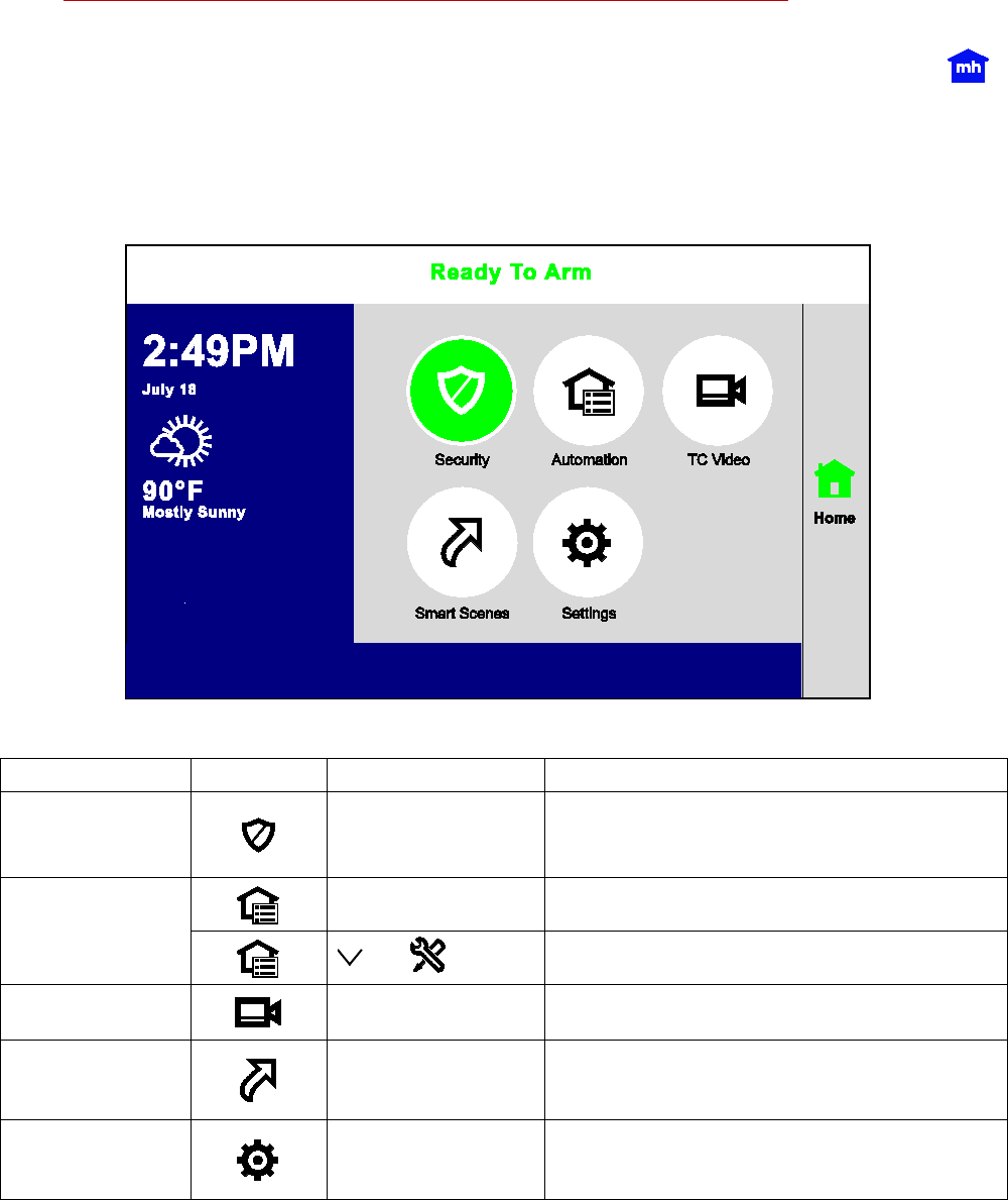
Navigating with the MyHome Gateway App
Use the MyHome Gateway™ App to manage your System Security, Automation, Smart Scenes,
Video and Settings:
The Home Menu
Function
Press…
Then…
Allows you to...
Security
Select from the
options on the next
screen.
Operate and manage the security features
and access other features of your Gateway
system.
Automation
--- Manually operate your Z-Wave devices
and Add or delete Z-Wave Devices
Video
---
View and configure system cameras;
manage video recovery functions
Smart Scenes
Master User Code
View and run automation scenes to operate
your system for convenience, comfort,
energy savings and security*
Settings
---
Adjust the Gateway touchpad and LED
brightness and the announcements and
chime volume
* Smart Scenes are created and deleted using Total Connect Remote Services.
NOTE: Pressing Home from any screen returns you to this Home screen.
13
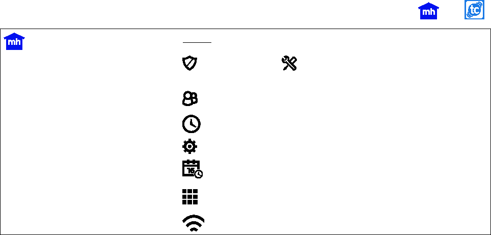
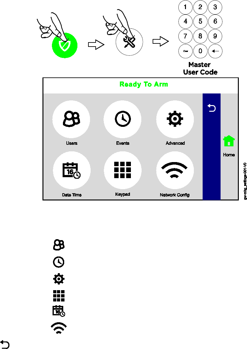
The Tools Menu
Home > Security > Tools
NOTE: The Master User code is required to access Tools.
This menu offers access to most of Gateway’s important settings and maintenance functions.:
Users
The Master User can add/remove other users and control users’
access to features. See
Users and Security Codes
.
Events View and export (?) system event logs. See
Events
.
Advanced
Access to software upgrades, tests and user maintenance functions.
Includes features found in
Maintenance
and
System Settings
.
Keypad Manage smart devices paired to your Gateway. See
Keypad
.
Date/Time Set the system’s calendar and clock. See
Date and Time
.
Network
Config
Configure Wi-Fi connection to the Gateway. See
Network
Configuration
.
(Back
Arrow) Return to the Security menu.
14
Security
Home > Security
IMPORTANT
If the Gateway is beeping rapidly when you enter the premises, an alarm has
occurred and an intruder may still be nearby.
LEAVE IMMEDIATELY and CONTACT THE POLICE from a safe location.
Security Features
NOTES: • For the Lyric Gateway to report alarms over the internet, your Wi-Fi network MUST
have power at all times.
• You must arm your security system in order for it to sound alarms.
Arming the System
The MyHome Gateway App displays the system arming status, top and center of the screen:
Ready to Arm = the system is ready to be armed.
Not Ready To Arm-Fault = one or more zones are faulted. The system cannot be armed until
all zone faults are fixed or bypassed.
Armed [Home, Away, Custom, etc.] = the system is armed, and arming mode description.
Before arming your system, all protected doors, windows, and other protection zones should be
closed or bypassed (see Bypassing Protection Zones).
To change the volume of countdown sounds and security status voice announcements, see
System Settings.
15
Arming states include
Arm Away
For times when no one is home; protects all perimeter and interior
zones.
Arm Home For times when the house is occupied; protects only perimeter zones.
Arm Custom Arms the system with pre-selected zones bypassed.
Bypass
This feature allows you to arm the system while intentionally leaving
selected zones unprotected.
Arm Night
For times when the house is occupied; protects perimeter zones and
selected interior motion sensors if used. Other interior zones are
unprotected. Enabled by your installer and only used with interior motion
sensors.
Instant For times when Entry/Exit doors
are not expected to open at all
.
Entry Delay is eliminated
. When the system is armed, an alarm occurs
immediately if an exterior door is opened.
Quick Arm
Used to arm the system in any mode without entering a user code, if programmed
NOTE: A user code is always needed to disarm the system.
Auto Home If you arm the system in the “Away” mode but no one exits, the alarm system
automatically changes to the “Home” mode. This helps to prevent unwanted
alarms when someone remains on the premises. Disarm the system and Arm
Away again when you are ready to leave.
This option is enabled by your
installer.
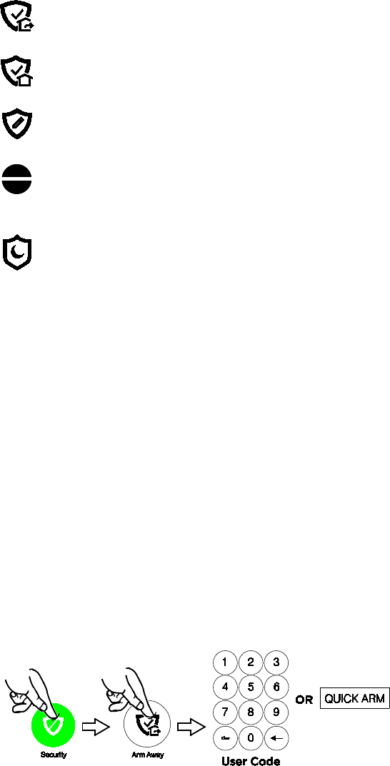
Arm Away
Security > Arm Away
By default, this mode’s exit delay countdown is accompanied by a beeping sound.
For a silent exit, press Silent Exit first.
• The system beeps twice and announces “Armed Away; exit now”. The exit delay
countdown begins.
• Press Restart Timer if you need more time to leave.
• Leave the premises and close the door before the countdown ends.
• The system arms in Away mode. (Door and window sensors and interior motion
sensors are active.)
16
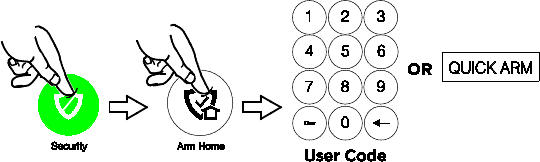
Arm Home
Security > Arm Home
By default, this mode’s exit delay countdown is silent.
• The system beeps three times and announces “Armed Home; exit now”. The exit delay
countdown begins.
• Press Restart Timer if you need more time to leave.
• The system arms in Home mode. Door and window sensors are active, but interior motion
sensors are not active.
Arm Custom
Security > Arm Custom
Use this option to pre-set zones for bypass when arming the system. You can also enable or
disable the entry delay.
1. Select Arm Custom to display a list of zones.
2. Select the zones you wish to bypass when arming the system.
3. Select Arm Custom on the zone list screen.
4. A numerical keypad appears.
Select Entry Delay if desired. (See Instant Mode for more about disabling Entry Delay.)
5. Arm the system by entering a user code.
6. The exit delay countdown begins.
7. If leaving, leave the premises and close the door.
Bypassed zones are left unprotected.
NOTE: The next time Arm Custom is used, the same zones that were previously
selected are highlighted on the zone list screen. If desired, select different zones for
custom arming.
Instant Mode
Security > Arm Custom
In Instant mode, an alarm occurs immediately when a protected Entry/Exit is opened. There is
no delay during which a code can be entered to disarm the system.
1. Select Arm Custom to display the zone list screen.
2. If any zones have been previously set for bypass, deselect them.
3. Press Arm Custom.
4. When the keypad appears, de-select Entry Delay.
5. Enter a user code to arm the system and leave the premises during exit delay.
Arm Night
Security > Arm Home
Arm Night
must be enabled by your security professional.
1. Select Arm Home to display the keypad.
2. Select Arm Night and then enter a user code.
3. The system beeps and announces “Armed Night Home mode”. Exit delay begins.
Press Restart Timer if you need more time to leave.
4. The system arms in Arm Night mode. Doors and windows and pre-selected interior
zones are active.
17
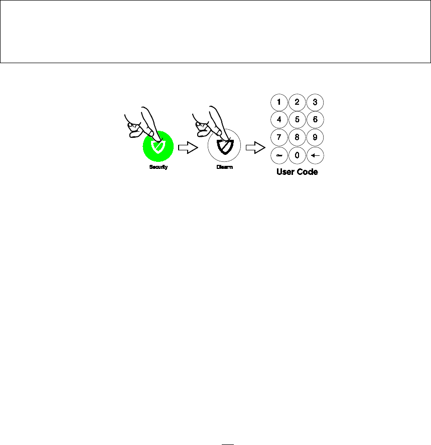
Disarming the System
Security > Disarm
NOTE: Disarming the system also silences audible alarms and trouble alerts.
IMPORTANT SECURITY NOTICE
Your wireless key (key fob) is similar to your keys or access card. If lost or stolen,
another person can compromise your security system. Immediately notify your
Dealer/Installer of a lost or stolen wireless key. The Dealer/Installer will then
remove the wireless key programming from the security system.
To disarm your security system:
• The system beeps and announces “Disarmed”, followed by alerts about system readiness,
if any. The announcement
• “Check system” indicates a faulted sensor or problems in the Gateway itself.
In most situations, if a valid user code is not entered within 30 seconds of pressing Disarm, the
Home screen reappears, and the system remains armed.
NOTES: • If a valid code is not entered by the time the entry delay ends, an alarm occurs.
• The Guest code and the Installer code can only disarm the system if that code was
used to arm the system. If the Quick Arm option has been used, neither the Guest
Code nor Installer Code can disarm the system.
User Code Error: When the screen displays User Code Error, it means too many invalid user
codes have been entered. The system will not accept additional user code entries
for 15 minutes (lockout period).
Bypassing Protection Zones
Bypass allows arming the system while intentionally leaving selected zones unprotected.
Bypassed zones will not trigger an alarm.
NOTES: • Fire and Carbon Monoxide (CO) and Emergency zones cannot be bypassed.
• Bypassed zones are automatically un-bypassed when the system is disarmed.
To Bypass zones:
1. Before arming the system, press Zones on the Security menu. A list of your system’s
zones appears. Faulted (open) zones are shown in red or orange.
Use the up and down arrows to scroll through the list of zones.
2. Select the zone(s) to be bypassed.
3. Press Bypass at the bottom of the screen. A keypad appears.
At the bottom of the screen, you can Bypass All Faulted, which selects all zones with
faults or other issues.
Press Select All to toggle through options for selecting zones.
4. Enter a user code. The zone list reappears with the Bypass icon shown for the affected
zones.
5. Arm the system as usual.
Press Clear Bypass to un-bypass any previously bypassed zones. Any zones with faults must be
addressed before arming the system.
18
Entry and Exit Delays
NOTE: Entry and exit delay times are programmed by your installer. There is room to jot
them down in Your System Information, near the end of this guide.
Entry Delay
Entry delay allows time to disarm the system when entering the premises. If the system is not
disarmed before the entry delay period ends, an alarm occurs. If programmed, the Gateway
beeps during the entry delay period as a reminder to disarm the system.
Two different entry delay periods can be programmed. The first is for the primary entrance,
typically, the front door. The second can be used for a secondary entrance, where more time
might be needed to walk to the Gateway to disarm the system.
Exit Delay
Exit delay begins immediately after the system is armed, providing time to leave through the
designated exit door without causing an alarm. In most situations, the MyHome Gateway App
screen displays a countdown of the remaining time. The exit door must be closed before the
end of the exit delay.
Typically, the system beeps slowly when counting down to Arm Away and the beeping
speeds up during the last 10 seconds of the delay period. The exit beeps cannot be silenced
unless Silent Exit is selected.
Restart Exit Delay
The Restart Timer option appears only if the option has been programmed by the installer.
Exit delay can be restarted once.
Exit Alarm
This option helps minimize false alarms sent to the monitoring company. Exit Alarm must be
enabled by your installer.
Exit delay begins whenever the system is armed.
• If an exterior door or protected interior zone is faulted during the exit delay (and remains
faulted when the exit delay ends), an exit alarm occurs and an entry delay countdown
begins.
• If the system is disarmed before the entry delay ends, the alarm sound stops and the
message Alarm Cancelled and any faulted zones appear.
• No message is sent to the monitoring company. Any open zones must be secured
before the exit alarm condition can be cleared.
To clear the display, press Disarm and enter a security code.
• If the system is not disarmed before the entry delay ends, and an entry/exit door or
interior zone is still open, the alarm sound continues and an Exit Alarm message is sent to
the alarm monitoring company, along with a “Recent Close” message (if the Recent Close
option is enabled).
• The message Alarm Exit Error appears. Faulted zones are also displayed. The alarm will
continue to sound until the system is disarmed or timeout occurs.
To stop the alarm, disarm the system. The message Alarm Cancelled will be displayed.
“Alarm” and faulted zones continue to be displayed.
To clear the display, press Disarm and re-enter the security code.
An exit alarm (“Alarm – Entry Exit”) also occurs if an entry/exit door or interior zone is faulted
within two minutes after the end of the exit delay.
19
Emergency Alarms
Available Emergency modes may vary, depending on the options programmed by your installer.
IMPORTANT
Use the Gateway Touchpad to trigger an Emergency. An Emergency can be
canceled or cleared from the Gateway Touchpad, the MyHome Gateway App or
Total Connect.
Activating an Emergency Alarm
1. Press on the Gateway.
2. Press the appropriate Emergency type option on the Touchpad.
Depending on the Emergency mode selected, an alarm tone sounds and the appropriate
alarm icon appears on the MyHome Gateway screen.
Pressing Police can send a silent message to your monitoring company if programmed to do
so. Verify this setting with your installer.
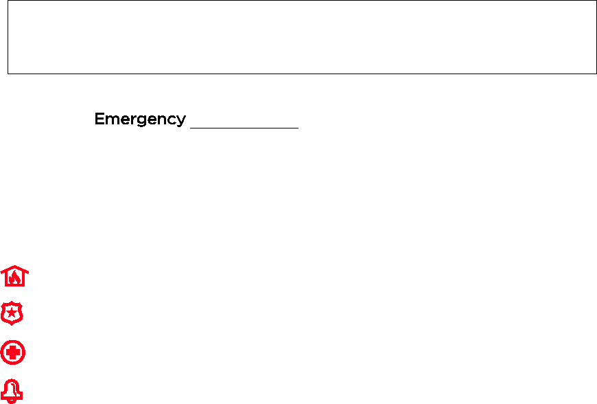
Common Emergency Icons
Fire
Alerts the monitoring company that a fire condition exists. (Displays Fire Alarm 995 Main
Fire)
Police
Alerts the monitoring company that a police emergency exists.
(Displays Alarm 999 Police, default is silent)
Medical
If programmed, alerts the monitoring company to other types of emergency.
(Displays Alarm 996 Main Medical)
Local
Activates sirens and sounders on premises without alerting the monitoring company.
(Displays zone 998)
Types of Emergency Alarms
Silent emergency
(silent alarm)
Sends an alarm signal to the monitoring company, but triggers no audible alarms
or display (on either the Gateway Touchpad or MyHome Gateway screen.)
Requires connection to a monitoring company.
Audible emergency
(audible alarm)
Sends an emergency message to the monitoring company, if connected. A
loud, steady tone sounds at the Gateway and external sounders if connected,
and an alarm appears on the MyHome Gateway App screen.
Personal emergency
or
Aux alarm
Sends an emergency message to the monitoring company if connected and
sounds at the Gateway and MyHome Gateway App, but not at external
sounders. An alarm icon appears on MyHome Gateway.
Fire alarm
Sends a fire alarm message to the monitoring company if connected. A
unique tone sounds at the Gateway and MyHomeGateway and external
sounders are activated if connected. A Fire alarm icon appears on MyHome
Gateway.
Local alarm
If programmed, activates the sirens and sounders on the premises without
sending a message to the monitoring company.
Cancelling an Emergency Alarm from MyHome Gateway
Depending on the type of Emergency alarm in effect, a keypad may appear immediately after
the alarm is initiated.
1. Enter a user code to cancel the alarm.
2. The audible alarms stop and Alarm Cancel appears.
If a silent alarm has been activated and the Home screen is displayed:
1. Select Security on the Home screen. Typically, a Disarm icon appears; a Security status
message such as “Alarm” may be displayed.
2. Press Disarm and enter a user code.
3. The screen changes to the normal Security menu.

20
Clearing an Emergency Alarm
After a Emergency alarm is cancelled, the Gateway continues to display zone information
associated with the alarm (this feature is known as Memory of Alarm).
To cancel and silence the alarm, enter a user code.
To clear memory of alarm on the screen, enter the user code again.
Memory of alarm can also be dismissed with these steps:
1. Cancel and silence the alarm with a user code as above.
2. Select Zones on the Security menu. The zone number associated with the type of
alarm appears.
3. Press Clear Alarms at the bottom of the screen.
4. Enter a user code. The Zones screen displays “No items to display!”
5. Press to return to the Security menu or press the Home button.
Chimes/Voice Annunciations
IMPORTANT
The Chime feature is intended for convenience and is not intended for life safety
purposes or pool alarm and does not meet the requirements of UL 2017.
Volume/Mute
Home > Settings
NOTES: • Chime and voice volume/muting can only be changed when the system is
disarmed.
• Voice annunciations are controlled by enabling or disabling Chimes.
• Voice annunciations should not be confused with Gateway’s Error! Reference
source not found. or Two-Way Voice (Audio Alarm Verification) features.
Gateway can give audible notifications when a protected zone opens while the system is
disarmed. With Chimes enabled three beeps (or a selectable tone) sound at the Gateway
when a protected zone is opened. If programmed, a voice announcement also sounds.
1. On the Home screen, select Settings.
2. Select Chime to enable chime sounds and voice annunciations. To mute all, de-select.
For chime sounds only, de-select Voice.
3. Adjust volume with the slider.
4. Press Save.
Setting Chime Sounds
Home > Security > Zones
NOTES: • Chime sounds can only be changed when the system is disarmed.
• Sounds can be changed only for door, window and motion sensors. Sounds
associated with smoke and CO detectors cannot be changed.
Different sounds can be assigned to the sensors in your system.
1. On the Zones menu, press Select All repeatedly to choose Select Chime. A list of
sensors appears.
2. Select a sensor. The Gateway displays available sounds.
3. Press repeatedly to choose a sound. (Options include Disabled.)
4. Press to save your selection and return to the Security menu.
21
Audio Alarm Verification (Two-Way Voice)
This feature allows your central monitoring station to listen to or talk with individual(s) on the
premises when an alarm has occurred (if programmed).
NOTES: • System announcements are disabled when this feature is active.
• Fire and CO alarms will prevent Audio Alarm Verification from operating.
• New Fire or CO alarms will terminate Audio Alarm Verification operation.
• Burglar alarms occurring during Audio Alarm Verification operation do not interrupt
operation and are reported immediately after operation concludes.
• Audio Alarm Verification modes are controlled by the central station.
22
23
Automation: Z-Wave and Other Devices
Home > Automation
IMPORTANT
Automation can ONLY be used for lifestyle enhancement. It must not be used for
personal safety or property protection.
Working with Z-Wave Devices
NOTE
Z-Wave automation functionality is supplementary only and has not been
evaluated by compliance agency.
Z-Wave technology is designed to automate devices in a home control network. The Lyric
Gateway is a security enabled Z-Wave device that supports Z-Wave Network Wide Inclusion
(NWI) Mode.
The Gateway and Z-Wave devices added to your system are linked together in a wireless
network. Each device in the network is assigned a unique address and cannot be activated by a
neighbor's Z-Wave controller. The Z-Wave network supports multiple controllers, allowing Z-
Wave remote controls to be used throughout the home.
NOTE: In some cases, a Z-Wave device might not report its status to the Lyric Gateway when
an action is initiated at the device itself. This varies with the manufacturer.
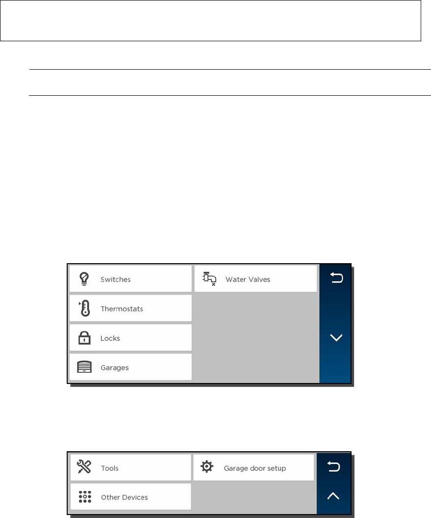
Press Automation on the Home screen. The Automation Management screen appears, initially
displaying categories of Z-Wave devices. (Your MyHome Gateway App’s display may differ from
these illustrations.)
This screen may also display “Press to see Failed Devices”. See Failed Devices (Failed Nodes)
for more information.
Press the Down arrow for more options:
Consult your installer about the options available in your system.
24
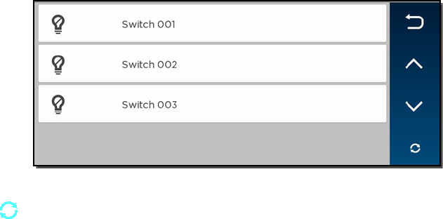
Selecting a device category opens a list of devices in that category. An example of the Switch
category is pictured.
For most devices, status is indicated by the color of the icon.
The Refresh button updates device status indications on the display.
Operating Z-Wave Devices Manually
1. On the Automation Management screen, select one of the device categories.
2. Select the device you wish to operate. Controls appear.
3. Lighting controls might offer an On/Off button or a slide control for dimmers.
4. Thermostats may display temperature set points and energy-saving features. The
options shown will vary with your device.
5. Operate the device as desired.
6. Press to return to the previous screen.
Adding Z-Wave Devices (Include)
NOTE: When adding a device, it may be necessary to perform the Exclude procedure
before the device can be Included successfully.
1. On the Automation Management screen, press the Down arrow.
2. Press Tools.
3. On-screen options appear, including Include Devices, Exclude Devices and
Advanced Tools. (View Failed Devices may also appear.)
4. Select Include Devices.
The panel enters Inclusion mode. Next, the panel displays “Ready to Include device.
Press the function button on device”.
5. Press the device’s Function button within 60 seconds. (Note that the location of the
Function button varies with the device you are adding. See the device’s instructions.)
The panel displays “Device Found. Please Wait”.
6. To include additional devices, repeat step 5.
OR
Press Abort to complete the Inclusion process.
7. Press to return to the previous screen.
Including Light Switches or Outlet Modules
Install the receptacle, wall switch or lamp/appliance module before Including it in your
system. Refer to the device’s instructions for more information about installation.
Z-Wave switches and outlet modules may vary. Refer to the device’s instructions to ensure
that it is Included properly in your system.

25
Including Door Locks
IMPORTANT
For security, Z-Wave door locks are encrypted, and enroll at low power
transmission range (approximately 6 feet). This requires Including the lock before
its installation in a door.
Assemble the lock, connect necessary cables and install batteries according to the device’s
instructions. Be sure the door lock’s orientation/handedness is correct.
Z-Wave door locks vary. Refer to the device’s instructions to ensure that it is Included
properly and to program a user code.
After Inclusion, install the lock within recommended Z-Wave range (see Wireless Range for
more information).
NOTES: • Program the 4-digit user code into the Gateway. When programming user codes
into the Gateway, determine if the user will have access to the Z-Wave lock. If so,
the user code will be transferred to the lock.
• If using a lock with Smart Scenes, automatic locking/re-locking features should be
disabled.
• Due to Low Power Inclusion Mode of secure devices, Include the Z-Wave Lock
first, if not using an Inclusion Tool/Remote Control. The lock should be installed
before including other devices.
• During operation, the system will display “JAMMED” and will revert to “Unlocked”
status if a jammed lock is detected.
• When performing a command directly from a thermostat or water shutoff valve, a
change of status message may not appear at the Controller.
Including Thermostats
Install and test the thermostat before Including it in your system. Refer to the device’s
instructions for more information about installation.
IMPORTANT
Honeywell is not responsible for property damages due to improper setting of
thermostat modes.
NOTES: • Some thermostats do not update temperature status automatically.
• When using Z-Wave thermostat control on the Gateway, the thermostat’s
scheduling feature should not be used.
• When the HOLD button on the Gateway’s thermostat control screen is
highlighted, Z-Wave scenes driven by Smart Scenes will not affect thermostat
operation. Additionally, if your system is connected to remote services, the
remote 7-day schedules will also not affect thermostat operation.
• For threshold monitoring to be configurable on the remote services and Z-Wave
thermostat screens, the respective zones will first need to be assigned with a
response type in zone programming. Threshold monitoring is not available on all
thermostats.
• Both Zones for each respective thermostat must be programmed (for example,
Zone 180 & 181 for thermostat #1, Zone 182 & 183 for thermostat #2 and Zone 184 &
185 for thermostat #3).
• When temperature is represented in Celsius, Gateway matches the temperature
increment of the particular thermostat for Heat, Emergency Heat and Cool set
points. Increments can be one degree or half degree, depending on the
thermostat.
• If Celsius scale is used in the thermostat, the Gateway must also be set to Celsius
scale.
• If the Energy Saving mode is set, the Gateway displays Energy Saving
Heat/Cooling Setpoint Temperatures that are programmed at the thermostat.
• An additional “Energy Saving” function in the thermostat is used to set/unset the
Energy Saving mode.

26
Lyric Gateway Z-Wave Thermostat Functions
Button
Function
Mode Select between HEAT, COOL and OFF.
Fan Select between ON, CIRCULATE and AUTO.
HOLD Allows temporary override of programmed Smart Scenes
that may operate the thermostat.
NORMAL Allows selected thermostat to run programmed Smart
Scenes.
NO SCHED Prevents Smart Scenes
from operating the selected
thermostat
Threshold
Monitoring Enable/Disable Threshold Monitoring Feature (if available)
Saving Off-
Saving On
Enables/disables the thermostat’s Energy Saving
Schedule Function.
EDIT Used to edit Thermostat name.
BACK Used to return to Thermostats screen.
Thermostat Energy Saving Mode
1. On the Automation Management screen, select
Thermostats
.
2.
Select the desired thermostat from the displayed list.
3.
On the thermostat control screen, press the “Saving Off” button OR
“Saving On” to activate or deactivate the thermostat’s Energy
Saving Schedule Function when a heating or cooling operation is
selected.
Deleting Z-Wave Devices (Exclude)
To delete (Exclude) a Z-Wave device:
1. On the Automation Management screen, press the arrow.
2. Press Tools.
3. Select Exclude Devices.
4. The panel enters Exclusion mode. Next, the panel displays “Ready to Exclude device.
Press the function button on device.”
5. Press the device’s Function button.
6. The device is excluded from the system and its information is displayed.
7. To delete another device, press Exclude on the right side of the screen.
OR
8. Press to return to the previous screen(s).
Editing Z-Wave Device Names
1. On the Automation Management screen, select the category that includes the device
you want to rename.
2. Select the device in the displayed list.
3. The device’s controls appear, showing the device’s default name.
4. Press Edit on the right side of the screen.
5. A keyboard appears on the touchscreen.
6. Press Clear to delete the default name.
7. Enter a custom name, using as many as 14 characters.
8. Save the device’s new name.
9. When you are finished editing, press to return to the previous screen(s).
27
Advanced Tools
1. From the Automation Management screen, open Tools.
2. Select Advanced Tools.
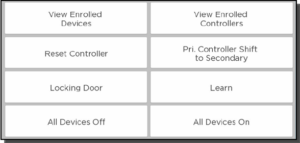
3. Enter the Master User code. The Advanced Tools screen appears:
View Enrolled Devices
Press to display Z-Wave device information: System Index/name, Secured or Non-Secured,
device type, device ID, manufacturer, node number.
View Enrolled Controllers
Press to display controller information: Primary or Secondary, Z-Wave Library Rev., Home ID,
device type, device ID, node number, manufacturer, Secured or Non-Secured.
Reset Controller
Press to delete all Z-Wave nodes in the Gateway, and reset the Gateway’s Home ID. When
prompted, press Yes to confirm.
Note that resetting the Gateway does not delete/Exclude individual Z-Wave devices.
Therefore, each device must be Excluded before being added/Included in the Gateway again.
Pri. Controller Shift to Secondary
Press to designate another controller (such as a Z-Wave remote control) as the Primary
Controller.
When the panel displays “Shifting”, start the “Learn” function on the secondary controller.
Refer to the secondary controller’s instructions for more information.
NOTE: Both controllers can operate the system’s Z-Wave devices, but only the Primary
can Include/Exclude devices.
Locking Door
Press to have your system arm automatically when a Z-Wave door lock is locked. Press
repeatedly to select Away mode, Home mode, Arm without Auto-Home mode or to Disable
this option.
Learn
This function is usually performed on a control panel or Z-Wave remote control being added
to the system as a secondary controller OR on a secondary controller being designated as
Primary.
Press after starting the Include or Shift Control function on the primary controller.
All Devices Off
Press to manually turn off all Z-Wave devices. Note that some thermostats will enter Setback
mode.
All Devices On
Press to manually turn on all Z-Wave devices. NOTE: Some thermostats will exit Setback
mode.

28
Failed Devices (Failed Nodes)
When the system tries to operate a Z-Wave device that has no AC power or other problems,
it is identified as a Failed Device. The system may take up to a minute after the operation to
detect the failure.
To view Failed Devices:
1. On the Automation Management screen, select View Failed Devices.
The panel displays “Failed Nodes Found!”
2. Press OK.
3. The device’s information is displayed. If multiple devices are listed, use the up and
down arrows at right to view the entire list.
NOTE: When troubleshooting, first make sure that power has been restored.
If a device is defective or otherwise unavailable, use the Fix All option.
1. Select Fix All on the right side of the screen. The system displays “This will delete all
failed nodes.”
2. Press Yes to confirm.
Devices deleted with Fix All must be added to the system again. See Adding Z-Wave
Devices (Include).
Failed Z-Wave devices are also indicated by a symbol on the Automation Management
screen or the symbol appearing in gray on the Home screen.
Important Notes About Z-Wave Devices
WARNING: NOT FOR USE WITH MEDICAL OR LIFE SUPPORT EQUIPMENT!
Z-Wave enabled devices should never be used to supply power to, or control the On/Off
status of medical and/or life support equipment.
Wireless Range
This device complies with the Z-Wave® standard of open-air, line of sight transmission
distances of 100 feet. Actual performance in a home depends on the number of walls
between the controller and the destination device, the type of construction and the number
of Z-Wave enabled devices installed in the control network.
Note that Z-Wave home control networks are designed to work properly alongside wireless
security sensors, Wi-Fi, Bluetooth and other wireless devices. Some 900MHz wireless devices
such as baby cams, wireless video devices and older cordless phones may cause interference
and limit Z-Wave functionality.
Things to consider regarding RF range:
• Each wall or obstacle (refrigerators, large TVs, etc.) between the remote and the destination
device can reduce the maximum range of 100 feet by approximately 25-30%.
• Brick, tile or concrete walls block more of the RF signal than walls made of wooden
studs and drywall.
• Wall mounted Z-Wave devices installed in metal junction boxes will suffer a significant loss
of range (approximately 20%) since the metal box blocks a large part of the RF signal.
Additional Z-Wave Information
• Gateway can control up to 72 Z-Wave devices.
• The system supports a maximum of 232 nodes (?). Note that a node is created every
time a device is Included, even if the device is being re-added to the system after
being Excluded. This can cause the number of nodes in the system to exceed the
number of actual devices.
• If the limit of 232 nodes is met and you need to add or re-Include more Z-Wave
devices, use the Reset Gateway function. Be aware that resetting the controller
deletes all of the system’s nodes, requiring all devices to be Included again. Node
numbers can be viewed by selecting Automation > Tools > Advanced Tools > View
Enrolled Devices. Remember that the system may require the Master User code for
access to Advanced Tools.
29
• The system is not aware of door locks being enabled with any temporary user
shutdown feature such as Vacation Mode. The system will continue to unlock a door if
programmed to do so via Smart Scenes.
• Z-Wave door locks with thumbturns: Certain models allow a brief period in which the
thumbturn can be operated manually before the device locks automatically. Locks of
this type are not recommended for use with Smart Scenes.
Z-Wave Compatibility
Z-Wave devices vary; follow the instructions provided with the specific device when including
and excluding devices into your Z-Wave network.
NOTE: Not all Z-Wave devices have been tested. Some functions may produce
unpredictable results.
Door Locks
Appliance
Yale® Real Living Push-Button Lever Lock HomeManageables Appliance Module
Yale Real Living Touchscreen Lever Lock Wayne Dalton Small Appliance Module
Yale Real Living Push-Button Deadbolt Lock GE® Wireless Lighting Control Plug-In
Appliance Module
Yale Real Living Touchscreen Deadbolt Lock Cooper In-Wall Duplex Receptacle Module
(Model RF9505-TDS)
Schlage® Link Deadbolt Lock
Lights
Schlage Link Lever Lock Leviton®/ViziaRF+® Switches
Kwikset® Smartcode Lever lock Leviton/ViziaRF+ Dimmers
Kwikset Smartcode Deadbolt Lock Leviton/ViziaRF+ Plug-In Appliance Modules
Thermostats
GE Wireless Lighting Control Dimmers
Honeywell Z-Wave Thermostat (ZWSTAT) GE Wireless Lighting Control Switches
Wayne Dalton Z-Wave Thermostat GE Wireless Lighting Control Plug-In Appliance
Modules
Trane® Z-Wave Thermostat Intermatic In-Wall Receptacle (Model HA01)
Residential Control Systems Thermostat
(Model TZ45)
Cooper Plug-in Lighting Switch Module (Model
RFAPM)
Intermatic InTouch Thermostat (Model
CA8900)
AEON Labs Lamp/Dimmer Module (Model
DSC06106-ZWUS)
Radio Thermostat Company of America
(Model CT30, CT32, CT100, CT101 and CT110)
Remotec Lamp Dimmer Module (Model ZDS-
100US)
Siren
Window Shades
FortrezZ SSA1/SSA2 Wireless Siren & Strobe Alarm Somfy® ILT Series
Water Valve
FortrezZ WV-01 Wireless Z-Wave Water Valve
EXISTING NETWORK NOTE:
Z-Wave products from other manufacturers can be included (added) into the
Gateway network. Z-Wave devices that are always powered can serve as repeaters regardless of
manufacturer.
USE OF THESE PRODUCTS IN COMBINATION WITH NON-HONEYWELL PRODUCTS IN A WIRELESS MESH
NETWORK, OR TO ACCESS, MONITOR OR CONTROL DEVICES IN A WIRELESS MESH NETWORK VIA THE
INTERNET OR ANOTHER EXTERNAL WIDE AREA NETWORK, MAY REQUIRE A SEPARATE LICENSE FROM
SIPCO, LLC. FOR MORE INFORMATION, CONTACT SIPCO, LLC OR IPCO, LLC AT 8215 ROSWELL RD.,
BUILDING 900, SUITE 950, ATLANTA, GA 303350, OR AT WWW.SIPCOLLC.COM OR WWW.INTUSIQ.COM
30
Garage Doors
Home > Automation > Garages
Garage door operation from the Gateway requires installation of a garage door control kit.
Consult your security professional for more information.
The Lyric Gateway can remotely operate and monitor as many as four garage doors. The system
can be armed when the garage door is opened. After it is closed, the zone will be monitored
without providing burglary protection.
The Gateway can automatically close garage doors if left open for more than a given time period
(Close in) or at a specified time (Close at). Garage doors can also be programmed for
monitoring only.
IMPORTANT
Do not use Gateway’s garage door automation with any garage door opener
that lacks the safety features required by U.S. federal safety standards (this
includes any garage door opener model manufactured before January 1, 1993).
A garage door opener that cannot detect an object and stop and reverse the
door does not meet current U.S. federal safety standards. Your garage door
opener also must signal before unattended door operation. For more
information please consult your garage door opener manual.
NOTE: Press Switches on the Automation Management menu to configure new Z-Wave
binary garage door openers. Ask your security professional for more information.
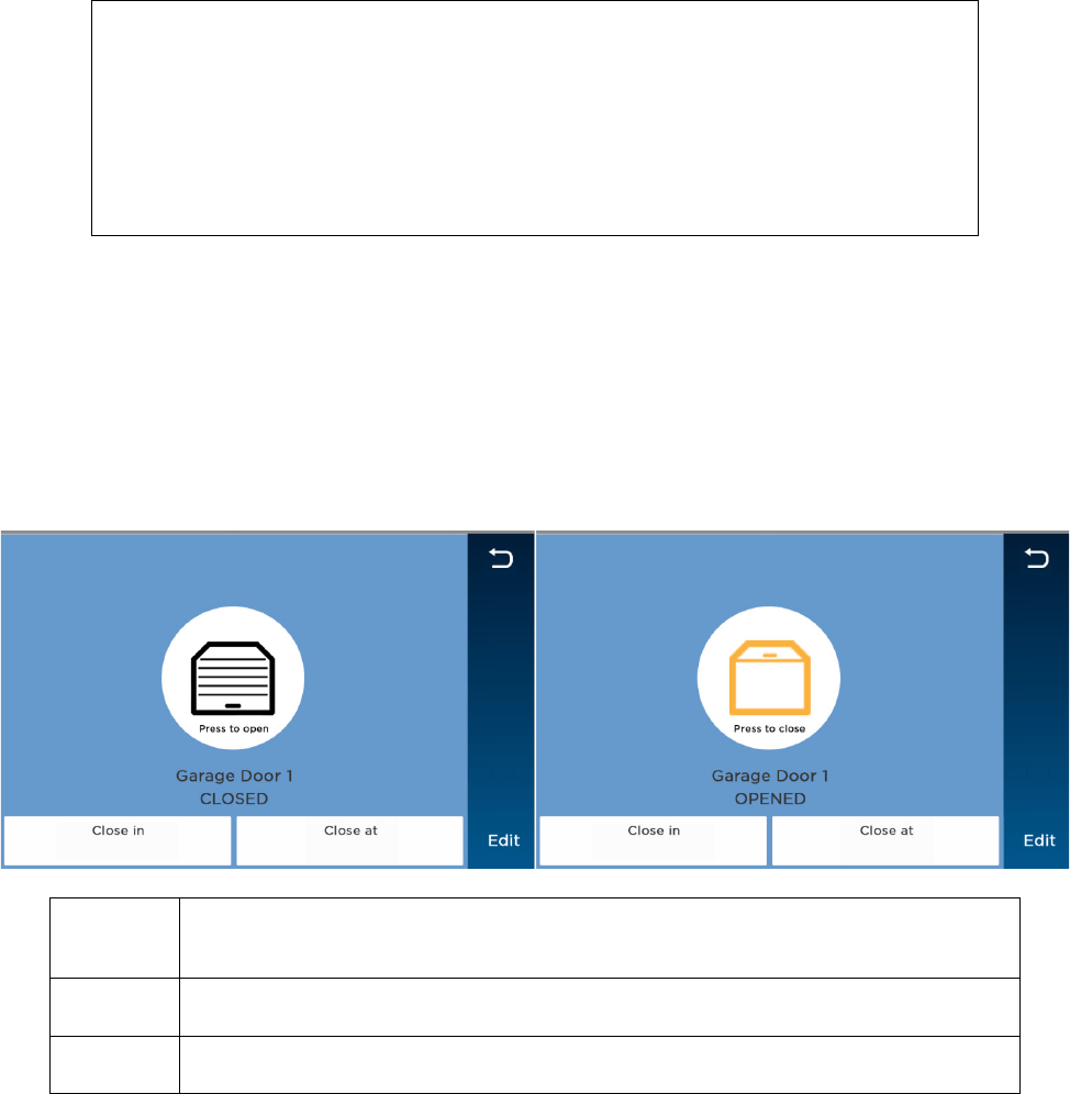
Garage Door Operation from the Lyric Gateway
1. On the Home screen, select Automation.
2. On the Automation Management menu, press Garages. The Controller /MyHome
Gateway App screen displays the Open/Closed status of your connected garage
doors.
3. Select the garage door you wish to operate.
4. Press the button in the middle of the screen to open or close the garage door.
Close in Use the keypad to set a specific time to wait before an open garage door closes
automatically (maximum 12 hours and 59 minutes). Use leading zeroes when
entering a number of hours less than
10
(“09:15” or “00:45”). Press
Done
to save.
Close at Use the keypad to set a specific time of day that an open garage door closes
automatically. Remember to specify AM or PM. Press
Done
to save.
Edit Press to rename the selected garage door. Use the on-screen keypad and press
Save.
NOTE: The Lyric Gateway does not support the status LED on the garage kit’s relay
module (Honeywell 5877).

31
Automation: Smart Scenes
Home > Smart Scenes
Smart Scenes are used to automate Gateway functions for comfort, energy savings and security.
Multiple settings can be put into effect with a single command. For example, selected lights can
respond to a door opening or movement in the middle of the night. Climate settings can be
controlled by your schedule and the security system can disarm automatically for expected visitors
or babysitters. Selected functions can be restricted to the homeowner, and limited access given to
children or guests.
IMPORTANT
When the Gateway is connected to a remote services account (e.g. Honeywell Total
Connect™), Smart Scenes can be created and modified ONLY via remote services.
Smart Scenes can be created, deleted or edited at the Gateway ONLY by the Master User. See Smart
Scenes and User Access for more about types of users and their access to different functions.
Three types of Smart Scene can automate combinations of security and lifestyle settings:
• Anytime: Initiated by users.
• Triggered: Initiated by the system in response to user-defined conditions.
• Scheduled: Initiated by the system’s calendar and clock.
Smart Scenes are frequently used in pairs. For example, a Smart Scene might be set to operate
multiple devices, turning on lights and opening blinds or shades. A second Smart Scene could be
used to return these devices to their Off or closed states.
NOTES: • As many as 100 Smart Scenes can be created at the Lyric Gateway or via Total
Connect remote services and the MyHome Gateway App.
• You can modify (Edit), manually start (Run) and review (Show) Smart Scenes prior
to operation.
• Scheduled and Triggered Smart Scenes can be paused with the Hold function.
• Setup details vary with each type of Smart Scene.
• Many buttons in Smart Scenes toggle through different options when pressed
repeatedly.
• The system treats security actions such as Arm Away, Arm Home or Disarm
separately from changes to lifestyle devices such as lights, locks and thermostats.
• Options that offer operations with both will display them in separate categories
called Security and Devices.
Smart Scenes and User Access
NOTES: • The Master User designates which types of user have access to each Smart Scene.
See Users and Security Codes for more information on different types of users.
• Smart Scenes can be created, deleted or edited ONLY by the Master User.
• The Add New button is available only to the Master User.
Regular users can Run and Show Smart Scenes created for Regular Users and Guests as well as
those designated “All Users”. Guests can Run and Show Smart Scenes created for Guests as well as
those designated “All Users”.
To work with Smart Scenes:
1. Select Smart Scenes on the Home screen. A keypad appears.
2. Enter a user code to display the Smart Scenes menu. From here, Smart Scenes can be
created or viewed by type.
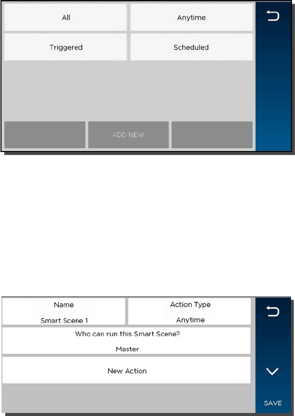
32
Creating a Smart Scene
Creating any Smart Scene involves these settings:
• Name
• The type of trigger that initiates the Smart Scene
• The type of user who can manually run the Smart Scene
• The resulting action(s) that take place when the triggering events or conditions occur
NOTE: Creating a Smart Scene should begin with giving it a Name.
1. Select Add New. (The default name that appears may differ from the illustration.)
2. Press Name.
3. Use the onscreen keyboard to enter a name and Save it.
4. Select the type of user who can run the Smart Scene. Choices include:
• Master
• Regular Users
• Guest
5. Press Action Type to toggle through the types of Smart Scene.
a. Anytime: Go to Step #6.
b. Scheduled: Go to Step #7.
c. Triggered: Go to Step #8.
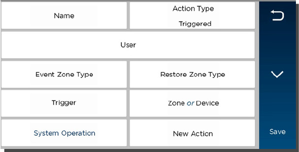
6. Select Anytime. These options appear:
• Name
• Action Type
• Who can run this Smart Scene? (User type)
• New Action
a. Press New Action to define the system’s response when the Smart Scene is
triggered.
b. When settings are complete, press until the Smart Scene appears with its name
displayed.
c. Press Save. Press to return to the main Smart Scenes menu.
33
7. Select Scheduled.
a. Select the type of user who can run the Smart Scene.
b. Select Scheduled to display clock and calendar settings.
c. Set a time when the Smart Scene will start. Be sure to specify AM or PM.
You can select Sunrise or Sunset instead of setting a time on the clock. Selecting
Sunrise or Sunset overrides the clock controls.
NOTE that updated Sunrise and Sunset times may depend on the system’s connection
to the internet or cellular phone network. Ask your installer for more information.
d. Set the days of the week for the Smart Scene to take place.
e. Press Save. The schedule settings are displayed.
f. Press New Action to define the response when the scheduled time occurs (see Step #8).
g. Press to return to the Smart Scenes menu.
8. Select Triggered Action. These options appear:
Smart Scenes can be started by one or a combination of the following options:
• Event Zone Type
• Restore Zone Type
• Trigger
• System Operation
NOTE: Event Zone Type, Restore Zone Type and Trigger can be different kinds of
conditions.
For example, a given Smart Scene can be triggered by a Fire alarm OR by an
Entry/Exit event. Smart Scenes can also be triggered by Trouble conditions
(Trouble as the Trigger in one of the system’s zones).
Device-related events (such as Light On, Light Off, Door Locked, Door
Unlocked) set the button at right to Device. Choices depend on the devices
installed in your system.
a. Event Zone Type starts the Smart Scene in response to any event (Fault, Trouble
or Alarm) in any protected Zone of a specific zone type. Select the desired option.
Typical zone types include:
• Entry/Exit (front and back doors)
• Perimeter (typically window sensors)
• Interior Follower (typically motion sensors)
• Day/Night (Usually assigned to sensitive areas where immediate notification of an
entry is always wanted.)
• 24 Hour Silent (Emergency button)
• 24 Hour Audible (Emergency button)
• Silent Burglary (typically a sensor)
• Fire No Verification (smoke detector)
• Fire With Verification (smoke detector)
• Carbon Monoxide (CO detector)

34
NOTE: Your system may include Zones that do not offer every Zone Type response.
b. Restore Zone Type starts the Smart Scene when any zone with the selected Zone
Type returns to its normal state (such as a door closing). The options are the same
as Event Zone Type options.
NOTE: Event Zone Type and Restore Zone Type are separate settings. For
example, a given Smart Scene can be triggered by a Fire Alarm (Fire No
Verification as the Event Zone Type) OR by an open door closing (Entry/Exit as the
Restore Zone Type).
c. Trigger starts the Smart Scene in response to a Fault, Trouble or Alarm in a
particular zone or changes to connected devices.
A note about triggering events:
Any change in the state of a security system zone is known as a Fault. Faults can
include Trouble and Alarm conditions. Trouble can include low battery or loss of
communication with the device. Alarm conditions include zone faults while the
system is armed and fire/CO sensors. Fault, Trouble and Alarm conditions can be
used to trigger a Smart Scene.
Fault: Any change in the state of a sensor triggers the Scene.
Trouble: Only Trouble conditions trigger the Scene
Alarm: Only Alarm conditions trigger the Scene.
Choosing one of these events sets the button at right to display Zone options.
Smart Scenes can also be triggered by changes in connected devices such as lights
and locks. These events include:
Light On
Light Off
Door Locked
Door Unlocked
Choosing one of these events sets the button at right to display Device options.
d. Choose Zone or Device, depending on your selection of a Trigger above. Security
zone sensors or devices such as lights and locks are listed.
e. Select the zone or device and Save.
f. System Operation starts Smart Scenes in response to security-related events. Options
include:
• Arm Away
• Arm Home
• Disarm
• Any Burglary Alarm
• Bell Timeout (end of the programmed time for which an alarm sounds)
• Start of Entry Delay
• End of Exit Delay
• Any Fire Alarm
g. Select New Action to define the response when the triggering event occurs.
NOTE: The 24 Hour Silent Alarm or 24 Hour Auxiliary Alarm Zone types will not
trigger the selected Smart Scene if the Any Burglary Alarm option is programmed.
9. New Action defines the response when the triggering event occurs. This includes
users manually running Anytime Smart Scenes, the time of Scheduled Smart Scenes
and the conditions for Triggered Smart Scenes. You can choose both Security and
automation device responses. The Security choices are:
• Arm the system in Away mode.
• Arm the system in Home mode.
• Disarm the system.
a. After choosing a Security setting, press and then Save.
b. If you choose to work with Devices, a list of the system’s automation devices appears.
35
c. Select one or more devices and set the device’s desired operation. (For example,
set switches to on or off, or locks to locked or unlocked.)
d. After adding a device and its desired operation to the Smart Scene, press Save.
Other available devices are displayed again so that they can be added to the Smart
Scene.
NOTE: In most situations, specific Security and Device information is displayed by
pressing the Down arrow.
10. Press Save.
11. Press to return to the Smart Scenes menu.
Hold
Hold allows Scheduled and Triggered Smart Scenes to be temporarily suspended.
A Scheduled Smart Scene can be put on Hold before programmed operations take place.
1. Select a Scheduled or Triggered Smart Scene.
2. Press Hold. The button is highlighted, and programmed operation will not take place.
To remove a Hold:
1. On the Smart Scenes menu, enter a user code with access to the desired Smart Scene.
2. Select the Smart Scene and un-highlight Hold. Programmed operation will resume.
Run
Smart Scenes can be manually started with the Run button. The Smart Scene’s results are
displayed when the programmed operations have been performed.
NOTE: The Run option can be used to check the outcomes of Scheduled Smart Scenes and
Triggered Smart Scenes, regardless of programmed triggers.
1. Select the Smart Scene.
2. Press Run. The system performs the programmed operations and the results are
displayed. Successful operations are displayed with device information and a check mark.
Failed operations are displayed with an empty circle.
Show (Review)
Use the Show button to see the programmed details of a Smart Scene without running it.
1. Select the Smart Scene.
2. Press Show. The scene’s category, authorized users and included devices are displayed.
36

37
Video
Home > Video
The Gateway can display live video from as many as eight Wi-Fi-connected cameras.
NOTE: Gateway and its cameras must be on the same Wi-Fi network.
IMPORTANT
If the Gateway loses AC power, the Video function is disabled to minimize drain on
the backup battery.
If power is lost while you are watching Wi-Fi cameras on the Gateway, video
display may continue briefly before being suspended.
When power is restored, the Gateway looks for available cameras. See Video Recovery.
Remember that interruption of AC power to your Wi-Fi cameras and your router
can also affect the Video function, even if the Gateway has AC power.
Viewing and Naming Cameras
1. Press Video on the Home screen. Video appears in windows or the cameras appear in a
list.
OR
The system may scan for cameras; when the scan is complete, the camera list appears.
From these screens, you can:
• Press to return to the Home screen.
• View live video.
• Name cameras.
• Add cameras to the system.
2. Select one or more cameras (as many as four) in the list.
• When multiple cameras are available, you may select as many as four.
• Selected cameras are highlighted and the Display option appears.
• You can also press Scan to search for other available cameras.
• Press a camera’s name again to de-select it.
3. Select Display to see video from the selected camera(s).
• Select Camera List to return to the list view.
• With multiple cameras displayed, you can select one to work with by tapping its
video window.
4. Viewing a single camera displays its details, which vary with the camera selected.
For all compatible cameras, you can:
• Name the camera. Select Name above the video display or Edit at right.
• Press Save on the on-screen keyboard.
• Press to show the camera full-screen.
• Press to return to the detail view.
Some cameras offer additional options such as pan/tilt and built-in lighting.
Adding a Camera
• Make sure that the camera is on the same Wi-Fi network as the Gateway system.
• Install the camera according to its instructions.
With the camera installed:
1. View or list cameras as above.
2. Press Scan. The system looks for available cameras.
3. When the new camera is found, you can name it as described above.
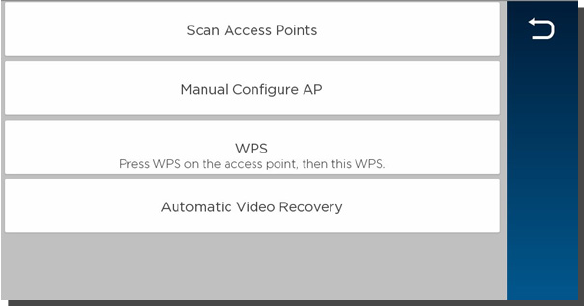
38
Video Recovery
Home > Security > Tools > Wi-Fi Config
If video from remote cameras is lost or becomes distorted, the system can attempt to reset video
streaming. By default, Gateway automatically begins to recover video about 60 seconds after
Wi-Fi communication has been restored.
The default setting is automatic video recovery. You may set recovery to begin only by user
intervention (Manual Video Recovery).
1. Press Security on the Home screen.
2. Select Tools. Enter the Master User’s security code.
3. Press WiFi Config.
4. Press Automatic Video Recovery repeatedly to choose between automatic and manual
operation.
5. Press to return to the Tools menu.

39
Users and Security Codes
Home > Security > Tools > Users
Gateway uses 4-digit codes to restrict certain functions to selected users. A special 4-digit code can
be set to trigger the system’s Duress function.
User codes can be used interchangeably when performing system functions (a system armed with
one user's code can be disarmed by another user's code), with the exception of the Guest Code
described below.
All users are automatically assigned a user number, which cannot be changed. Do not confuse these
user numbers with user codes.
User Codes
Master User This code is usually set when the system is installed, and can be
changed later. Typically, the Master User is a household member
who can perform all system functions.
Only
the Master User can add and remove users or modify their
settings. Settings include assigning security codes and user names.
Only
the Master User can create
Smart Scenes
. Access to Smart
Scenes for other users is controlled by the Master User.
User Typical users are household members and other authorized persons
who can arm and disarm the security system, with controlled access
to other system features.
Guest Visitors and others who are authorized to arm/disarm the system
only at certain times or on a temporary basis.
The Guest’s user code can be used to
arm
the system, but cannot
disarm
it unless the system was armed using the Guest code. The
Guest’s user number is
47
.
Duress Code
IMPORTANT
The Duress function requires connection to an alarm monitoring service.
Household members and authorized visitors can enter this code if forced to disarm or arm the
system under threat. When the Duress code is entered, the Lyric Gateway and keypads appear to
behave normally, but the system silently notifies your alarm monitoring service. The Duress
Code’s user number is 48.
NOTES: • A security code cannot be assigned more than once. If an existing code is entered,
the system displays the warning User code not accepted! If this occurs, press OK to
return to user settings and assign a different code.
• The system should be disarmed before you work with user codes.
• Limited-access users such as guests and cleaning staff should not be instructed on
system functions other than those they will be using.
• The number of user codes supported by a Z-Wave door lock can vary between
manufacturers. To ensure compatibility with Gateway, set the length of the Master
User code on the door lock to be greater than four digits (?).
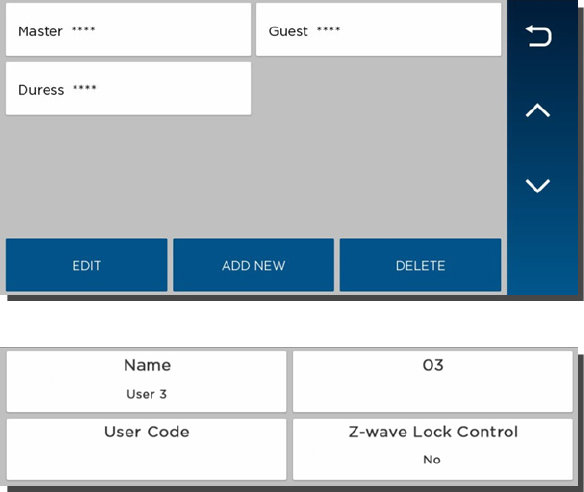
40
Adding Users and Assigning Codes
1. On the Home screen, press Security.
2. Press Tools, and enter the Master User code.
3. Select Users. Existing Users are displayed, along with the Guest and Duress code listings.
Four asterisks appear on each listing that has a security code already established.
See User Settings for full details.
4. Create and change settings in the menu shown here (the details may vary):
a. Create User: Press Add New and a new user screen like the one pictured above appears.
Set the details as desired.
b. Define/Change Guest Settings: Press Guest and then Edit.
c. Set/Change Duress Code: Press Duress and then Edit. Enter a 4-digit code.
5. Save after making settings. The list of user codes reappears.
6. Press to return to the Tools menu.
Changing Security Codes or the Duress Code
The Master User can change other users’ names and security codes as well as delete users from
the system.
1. Access the Users screen as shown above.
2. Select one of the listed users.
3. At the bottom of the screen, press Edit. User details appear. Note that a user’s number in the
system, seen at upper right in the user details, cannot be changed.
Deleting a User
The Master user can delete secondary users from the system.
1. Select one of the listed users.
2. At the bottom of the screen, press Delete. Gateway requests confirmation.
3. Press Yes.
41
User Settings
User Name
Newly-created users are given a default name. To customize a user’s name:
1. Press Name at upper left on the display. A keyboard appears.
2. Press Clear to delete the default name.
3. Enter the desired name, using as many as 10 characters.
4. Save. User details appear.
5. Press Save again. The list of users appears, displaying your changes.
User Code
Newly-created users have no security code. To assign a code:
1. Press User Code. A keypad appears.
2. Press Clear if you are changing an existing code.
3. Enter a four-digit code.
4. Press Done. User details appear.
5. Save. The list of users appears.
Users and Z-Wave Lock Control
NOTE: This option appears only if Z-Wave devices are connected.
Each user can be given the ability to disarm the system by entering their code to open a Z-
Wave lock.
When creating or editing a User:
1. Set Z-Wave Lock Control to Yes. Z-Wave Unlocking Door appears.
2. Select Disarm.
3. Press Save.
With this setting, entering a user code at any Z-Wave door lock in the system unlocks the
door and disarms the security system.
42
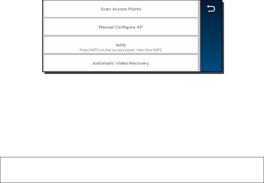
43
System Settings
Brightness/Volume
Home > Settings
Adjust voice and system sounds with the Volume slider. System sounds include zone alert chimes
and countdown beeps.
Adjust touchscreen brightness with the Brightness slider.
NOTES: • As the sliders move, the Controller previews changing volume and brightness levels.
• Voice annunciations are controlled by enabling or disabling Chimes.
Wi-Fi Configuration
Home > Security > Tools > Wi-Fi Config
Manage your system’s router here. Remember that the Gateway and all Wi-Fi cameras must be
on the same network.
To View or Join Available Wi-Fi Networks
1. On the Tools menu, press the Wi-Fi Config button. A list of Wi-Fi options appears.
2. Press Scan Access Points. A list of available networks is displayed. Use the up and
down arrows to scroll through the list. Press to return to the previous screen.
3. Select the desired network and press Edit. The network information is displayed. If a
password is required, press Key and enter the password.
4. Press Save.
5. Press JOIN.
6. Press to return to the previous screen.
Manually Configure Access Point
IMPORTANT
The Security setting below must match the security protocol used by your network
router.
1. On the list of Wi-Fi options, press Manual Config AP. The Wi-Fi enrollment menu
appears. (Fields include Network Type, which cannot be changed.)
2. Press SSID Name.
3. Enter the network’s name.
4. Press Save.
5. Press Security.
6. Choose the same security protocol as your router. Options include Open, wpa/wpa2
and WPA2. (WEP is not supported.)
7. If a password is required, press Key, and enter the password.
8. Press Join. A confirmation screen appears.

44
9. Press OK and Save.
10. Press to return to the previous screen.
Join a WPS Network
1. On the Gateway, have the list of Wi-Fi options ready. Don’t press any buttons yet.
2. Press the WPS button on the access point device or router.
3. On the list of Wi-Fi options, press WPS. The Controller / MyHome Gateway or TC
displays “Please Stand by for WPS Operation”.
4. If the operation is successful, the Controller / MyHome Gateway or TC displays
“Device has been successfully added to the network”.
5. Press OK.
If the operation is not successful, the Controller / MyHome Gateway or TC displays Failed
Operation. Device not added to the network. Press OK.
Automatic/Manual Video Recovery
If video from remote cameras is lost or becomes distorted, the system can attempt to reset
video streaming. By default, Gateway automatically begins to recover video about 60
seconds after Wi-Fi communication has been restored.
The default setting is automatic video recovery. You may set recovery to begin only by user
intervention.
• On the list of Wi-Fi options, toggle between Automatic Video Recovery and Manual
Video Recovery.
• Press to return to the Tools menu.
Software Updates
Home > Security > Tools > Advanced
Lyric Gateway
Software updates for the Gateway are published periodically. Some updates request user
permission in an on-screen window. Press Accept, Yes or OK to install the update.
Certain critical updates are installed automatically. After updates of this type, information
about the update is displayed on-screen.
You can see the current version of the Gateway’s software at Security > Tools > Advanced >
System Information.
IMPORTANT
After a new SiX™ series sensor or key fob is enrolled in your system, the new
device’s software should be updated. This ensures that you are using the most
up-to-date version of the software.
Sensor Firmware
Normally, SiX™ Series sensors in your system are updated when the Gateway’s software is
updated.
To initiate sensor firmware update manually:
1. On the Advanced menu, press Update Sensor Firmware.
2. Press Start and follow the instructions on the screen.
3. Press Stop when the update is complete.
4. Press to return to the Advanced menu.
Key Fob Firmware (Wireless Keys)
45
SiX™ Series wireless keys:
We recommend that you have the key fob handy so you can work with it as instructed during
this procedure.
1. On the Advanced menu, press Update Keyfob Firmware.
2. Press Start and follow the instructions on the screen.
3. Press Stop when the update is complete.
4. Press to return to the Advanced menu.
Other types of wireless key:
Ask your installer about updating your system’s other wireless keys.
Date / Time
Home > Security > Tools > Date Time
Gateway’s clock and calendar are normally updated via the Gateway’s network connections.
Use these controls to set date and time manually. Don’t forget to specify your time zone and
Daylight Savings Time if necessary. Be sure to Save your changes.
If Gateway is reconnected to the cellular phone network or the Internet, the clock and calendar
are updated automatically.
Events
Home > Security > Tools > Events
The Gateway keeps a log of system events such as:
• Arm/Disarm
• Alarm, Trouble and Fault
• Changes in status of Z-Wave devices
The system can save up to 6000 events. When the log is full, the oldest 2000 entries are deleted
to make room for logging new events.
Logs can be viewed at the MyHome Gateway App or TC or exported in a variety of file formats.
See Event Log Codes for a list of logged events and how they are displayed.
Viewing Events
1. On the Tools menu, press Events. The MyHome Gateway App Events screen lists all
events, sorted chronologically.
2. Press All to select different sorting options (Alarm, Trouble, Bypass, Open or Close
or Non-Security).
3. Select All on the list to return to the view of all events.
Exporting Events
1. Display events as above and press Export Logs.
2. When prompted, connect a USB storage device.
3. Select a file format. A progress display appears. When export is complete, the
previous screen appears.
4. Remove the USB storage device.
Keypad
Home > Security > Tools > Keypad
This menu displays the MAC ID of mobile devices connected to Gateway via the Honeywell
MyHome Gateway app.
The MAC ID is listed here when the app is first configured for use with Gateway.
To disconnect a device, touch its listing on the screen and press Delete.
The Gateway MyHome Gateway App requests confirmation; press Yes to proceed.

46
Testing Your System
NOTE: TESTING SHOULD BE PERFORMED WEEKLY.
Before testing, the system should be disarmed and all protected doors and windows closed. The
Home button should show green.
No alarm messages are sent to your alarm monitoring company during these tests.
Press Tools and enter the 4-digit Master User code. Press Advanced.
Testing Sensors (Walk Test)
Home > Security > Tools > Advanced > Walk Test
Start by pressing
Walk Test
.
The Gateway’s internal sounder loudly sounds and
Walk Test – Home to Quit
appears. The
Gateway then beeps every 30 seconds as a reminder that the system is in Test mode.
Note that Walk Test mode automatically quits after 4 hours.
Doors and Windows
Open each protected door and window in turn and listen for three
beeps from the Gateway. If programmed to do so, each zone’s voice
descriptor is heard. Identification of protection points with problems
should appear on the display MyHome Gateway App screen.
Notifications of problem zones clear when the door or window is
closed.
Motion Sensors
Walk in front of each sensor and listen for three beeps and/or voice
descriptors.
The device’s identification should appear on the display when it is
activated. The display clears when no motion is detected.
NOTE
: If wireless motion detectors are in use, there is a 3-minute
delay between activations, which helps preserve battery life.
Fire/Carbon Monoxide
sensors
Follow the manufacturer’s instructions to test these devices. When a
device is activated, its identification should appear on the touch
MyHome Gateway App screen.
IMPORTANT
When testing smoke detectors, keep the Lyric Gateway in test mode for
at
least one minute (60 seconds)
after testing the detector to avoid sending
unwanted alarm messages to your central station monitoring company.
If there is a problem with any sensor (no confirming sounds, no display), notify your service
company.
When all sensors have been checked (and doors and windows closed), no zone identification
numbers should be displayed.
Finish by pressing Home and entering the Master User code.
47
Testing Communications
Home > Security > Tools > Advanced > Comm. Test
These tests check the system’s cellular network and internet (Wi-Fi/Ethernet) connections.
On the Advanced menu, press Comm. Test. The options may vary with the devices installed in
your system. Select the desired option to test connectivity and/or send test messages to the
Central Station.
If the test is successful, the MyHome Gateway App screen displays Service OK or ACK Received.
Details of the test may be shown.
Test Ethernet
Checks internet connectivity without sending test messages.
Send Any
Sends test messages via all available connections.
Send Cellular
Message
Sends test messages via cellular network.
Send Ethernet
Message
Sends test messages via internet.
Finish by pressing to run a different test or by pressing Home. Enter the Master User code if
prompted.
Reboot
Home > Security > Tools > Advanced > Reboot
Press Reboot to restart the Gateway if required. The system requests confirmation (“Are You
Sure?”). Press Yes to proceed.
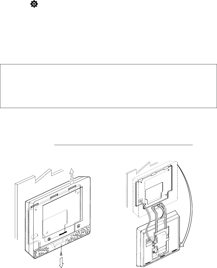
48
Maintenance
The Lyric Gateway is designed to require little maintenance. However, testing your system is strongly
recommended, and regular cleaning is suggested.
•
Test the system weekly.
• Test your system after any alarm occurs.
See
Testing Your System
for more information.
Care and Cleaning
• Do not slam sensor-protected doors or windows.
• Keep dust from accumulating on the Gateway and sensors, particularly motion sensors
and smoke or carbon monoxide detectors.
• The Gateway and sensors should be cleaned carefully with a soft, dry cloth. Do not clean
the components with water or any other liquids.
Select Settings on the MyHome Gateway App screen.
Press Clean. During the 15 second countdown, a soft, damp cloth can be used on the screen
without affecting the controls.
NOTE: When the security system is armed, system event notifications will cancel the cleaning
mode and return the system to normal operation. When the system is disarmed, only
certain notifications will cancel cleaning mode.
Battery Replacement
Home > Security > Tools > Advanced > Install Backup Battery
IMPORTANT
Replace the battery pack when the Security menu displays Low Battery with no
zone number specified.
Use only batteries recommended by the installer or the manufacturer.
Disarm the system before changing the Controller’s battery pack.
Remember that you must enter the Master User code for access to the Tools menu.
Gateway Controller
1. Select Advanced on the Tools menu.
2. Select Install Backup Battery. Gateway requests confirmation that you want to
proceed.
3. Press Yes and leave the battery installation procedure screen open.
4. ***Need new Procedure *** Open the Controller’s case. If wall mounted, hang it from
the self-contained hook as shown below.
Need New Graphics
Remove the b ody of the Controll er from its wall mo unt or remove the desk m ount from the back of the Controller.
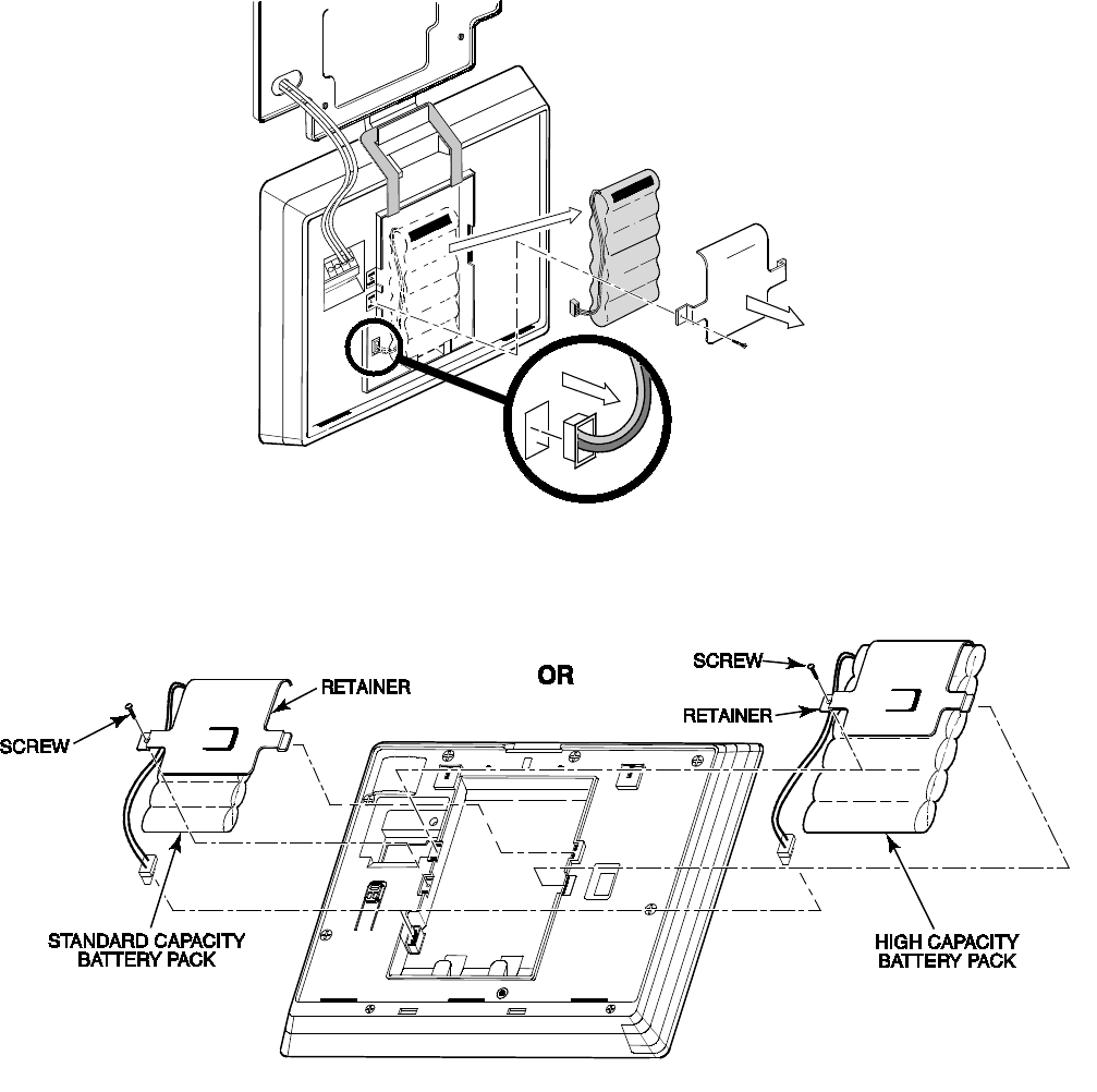
49
5. Unplug the battery and remove it as seen below.
6. Install the replacement battery; remember to replace the connector inside the battery
compartment.
7. Depending on your choice of a standard- or high-capacity replacement battery,
position the battery retainer clip as seen below.
8. Close the case and replace the screw shown in Step 4.
9. Return the Controller to its mounting location.
10. Press OK on the battery installation procedure screen.
11. The system confirms “Battery successfully installed".
12. Press OK. The system returns to the Advanced menu.
13. Press to return to the previous screen(s).
Sensors
Clear sensor low-battery warnings by entering a user code on the Controller. Follow the
sensor’s battery replacement instructions.
NOTES: • For SiX™ series smoke sensors, remove the battery and wait for 2 minutes before
installing the replacement battery. (?)
• For other SiX™ series sensors and wireless keys, remove the battery and wait
about 10 seconds before installing the replacement battery.
Need New Graphics
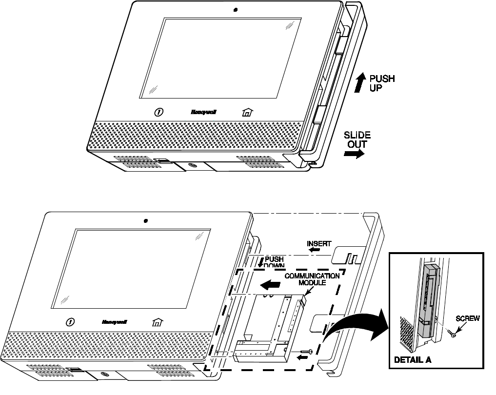
50
Communication Module Replacement
Home > Security > Tools > Advanced > Install Cellular Module
Refer to the illustrations below and follow these steps to replace a communication module:
Removing the Bezel
Installing the Communication Module
1. With the system not armed, select Tools on the Security menu.
2. Enter the 4-digit Master User code.
3. Select Advanced.
4. Select Install Cellular Module.
Follow the on-screen instructions for changing the module.
5. Press OK on the screen in step 4. The system confirms installation.
6. Press OK. The system returns to the Advanced menu.
7. Reboot the Controller (see Reboot for details).
Need New Graphics
THEN
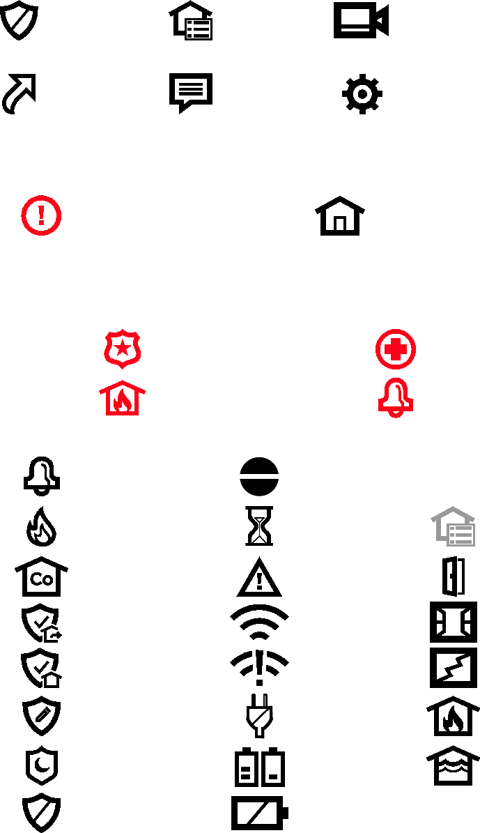
51
SYSTEM DISPLAY and Buttons
Zone numbers, location and other information may be displayed with status indications.
Failure and Trouble indications and panel Emergency buttons appear in red.
Home Screen
Security Automation Video
Smart Scenes Notices Settings
Control Panel Buttons
Below Touchscreen
Emergency
Press and hold for on-screen options
Home
Press to return from other screens
On-screen Emergency Buttons
Police
Medical
Fire Local Alarm
System Status and Security
Alarm
Bypassed Zone
Fire Alarm
Restart Timer
(more Exit time)
Automation
Failure
(Z-Wave problem)
CO Alarm
Trouble/Alert
Details on Security menu
Door Open
Arm Away
Wi-Fi
(signal strength)
Window Open
Arm Home
Wi-Fi Loss Glass Break
Arm Custom
AC Power Loss
Fire or Heat
Sensor
Arm Night
Home
Low Battery
Flood Sensor
Disarm
No Battery
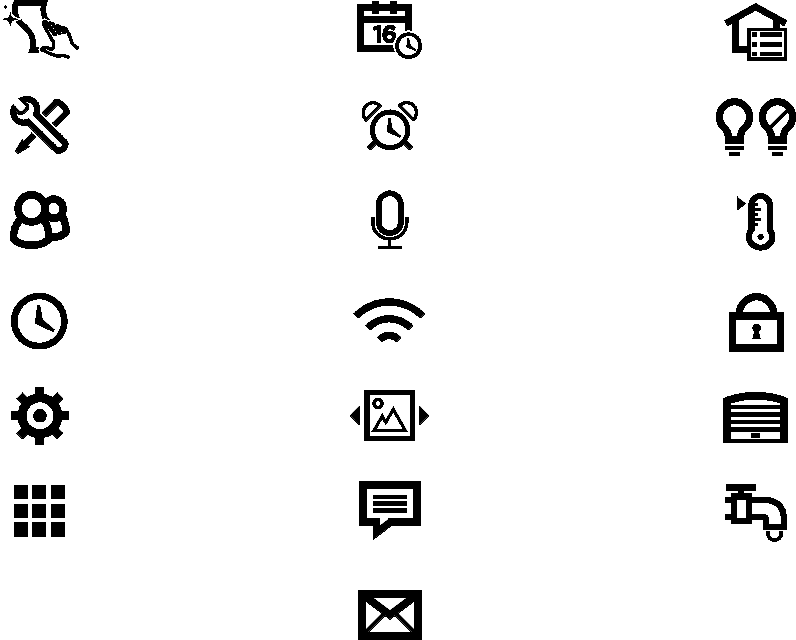
52
Features/Various
Icons may appear in red or orange to indicate device status. Problems involving Z-Wave devices are
indicated by the Automation icon appearing in gray on the Home screen.
Clean Control
Panel
Date/Time
Automation
Tools
Reminders
Switches
Users
Voice
Command
Thermostats
Events
Wi-Fi
Config
Locks
Advanced
Slide Show
Garages
Keypad
Notices
Water
Valves
Message
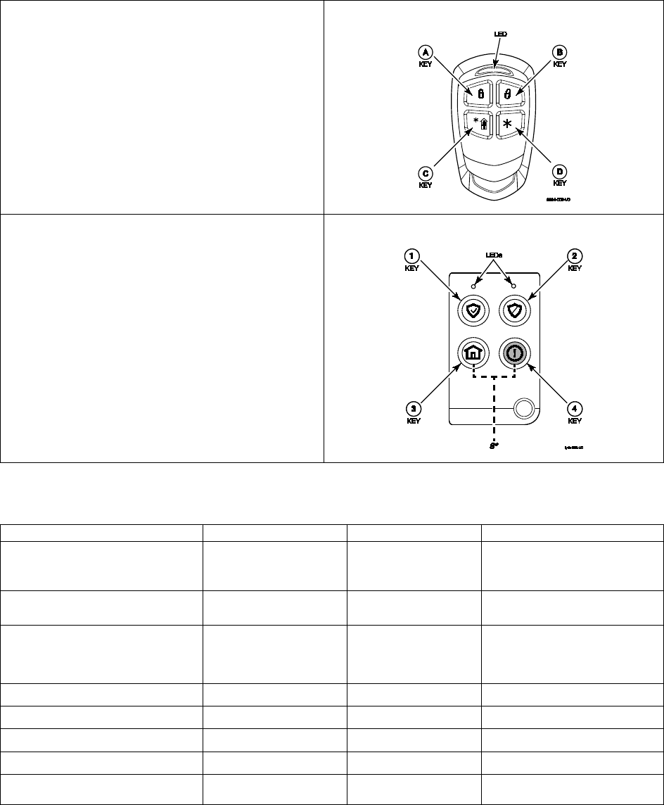
53
WIRELESS KEYS
Key Assignments
Your wireless keys (key fobs) are set up by your installer. You might wish to write down each
button’s preprogrammed function in the space below.
NOTES: • One or more buttons may have been programmed for Emergency function.
• To activate a button function, press and hold the button for 1-2 seconds.
Button A: ___________________
Button B: ___________________
Button C: ___________________
Button D: ___________________
5800 Series wireless key
Button 1: ___________________
Button 2: ___________________
Button 3: ___________________
Button 4: ___________________
Button 8*: ___________________
(press and hold BOTH buttons to activate)
SiX™ Series wireless key
SiXFOB Wireless Key Status Indications
Press and release any key for system status. Status is indicated by the LEDs at the top of the key fob.
Green LEDs
Red LEDs
Sounder
System Status
Rapid Flash – Alternating about
8-20 seconds, then ON for 3
seconds
Off Chirp for
confirmation Device Enrollment
Off ON 2-3 seconds 2 Beeps System Armed (any mode)
Off Slow Flash for 2-3
seconds 4 Beeps
Alarm in progress or
system in Audible Panic Mode
ON 2-3 seconds Off 1 Beep Disarmed, Ready to Arm
Slow Flash for 2-3 seconds Off Silent Disarmed, Not Ready to Arm
Flash once (both LEDs) Off Silent RF Transmission
Off Off 1 Second beep Not Hearing from Controller
Rapid Flash for 2 seconds Off Silent Deleting wireless key from
system

54
Event Log Codes
The Gateway’s Event Log can record and display as many as 6000 system events. Events are stored
locally in the Gateway, in chronological order and sent to your monitoring company as needed.
When the maximum number of stored events is reached, the oldest 2000 entries are deleted to
make room for logging new events.
The type of events that can be recorded is selectable; refer to the Gateway Installation and
Reference Guide’s Programming section. The Events and CID Codes displayed vary with your
system’s options. The tables below provide definitions of the events/codes that may be transmitted
to the Central Station and/or displayed by the MyHome Gateway App.
Note: If the Gateway’s backup battery is exhausted after AC power is lost, any system activity
occurring after Low Battery notification is not saved. Additionally, the Gateway will revert to the
status condition as before the low battery notification.
Contact ID® Event Log Codes
CID Code
Definition
Event Log Display
110
Alarm, Fire Fire
121
Alarm, Duress Duress
122
Alarm, Silent Silent
123
Alarm, Audible Audible
131
Alarm, Perimeter Perimeter
132
Alarm, Interior Interior
134
Alarm, Entry/Exit Entry/Exit
135
Alarm, Day/Night Day Night
137
Alarm, Tamper Tamper
145
Expansion Module Tamper Expansion Module Tamper
146
Silent Burglary Silent Burglary
150
24-Hour Non-Burglary 24 Hour Non-Burglary
162
Carbon Monoxide Detected Carbon Monoxide Detected
301
Trouble, AC Loss AC Loss
302
Trouble, Low System Battery Low system battery
305
Trouble, System Reset System Reset
308
System shutdown System shutdown
316
System Tamper* System Tamper
341
Trouble, Case Tamper Cover Tamper
344
Trouble, RF Receiver Jam Detect RF Jam Detect
350
Long Range Radio Reset Long Range Radio Reset
353
Trouble, Long Range Radio Transmitter Fault Comm. Trouble
354
Failure to Communicate Event Failure to Communicate Event
373
Trouble, Fire Trouble Fire trouble
374
Trouble, Exit Error Alarm Exit error alarm
380
Trouble, Sensor Sensor trouble
381
Trouble, Loss of Supervision RF Superv Loss-RF
383
Trouble, Sensor Tamper Sensor Tamper
Continued next page
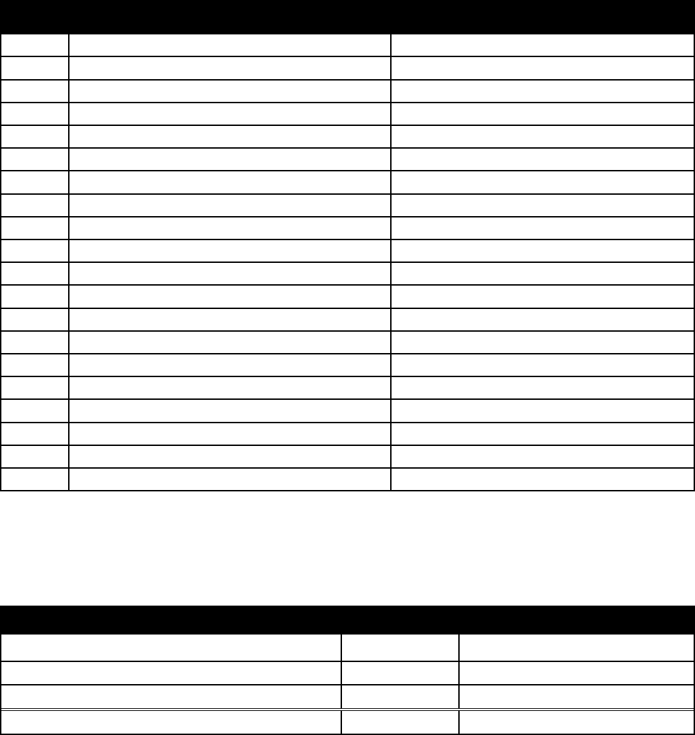
55
Contact ID® Event Log Codes
384
RF Low Battery RF Low Battery
401
Open/Close by User Arm Away/Disarmed
403
Open/Close Automatic Automatic O/C (or Scheduled Arming)
406
Cancel Cancel
407
Remote Arm/Disarm Remote Arm/Disarm
408
Quick Arm Quick arm
441
Armed Home Arm Home/Disarmed
455
Auto-Arm Failed Auto-arm Failed
459
Recent Close Recent Closing
461
Wrong Code Entry Wrong Code Entry
570
Zone/Sensor Bypass Zone Bypass
601
Manual Trigger Test Report Manual Trigger Test Report
602
Periodic Test Report Periodic test report
606
Listen-in to follow
Listen-in to follow
607
Walk Test Walk Test Mode
623
Event 90% Full Event Log 90% Full
627
Program Mode Entry Program mode entry
628
Program Mode Exit Program mode exit
654
System Inactivity System Inactivity
655
Reset Master Code User Code
*If APL is enabled, AlarmNet 360TM will generate a special comm. fail message (E316) if it does not hear from a unit within 15 minutes
after a delayed alarm is delivered. This message is meant to alert the Central Station that the system has been tampered with and may
have been compromised.
Central Station Messages
The following messages are sent by the controller internal cellular or WiFi devices for the conditions
listed below.
Alarm Condition Alarm Code Restore Code
Power On / Reset
E33900950
Primary Communication Path Supervision
E350C0951
R350C0951
Secondary Communication Path Supervision
E350C0952
R350C0952
Test
555555559
56
Glossary
Zone Specific areas of protection in your home. Sensing devices are assigned to these
numbered Zones, with designations such as front door, kitchen window, etc. Zone
numbers appear on the display when an alarm or fault occurs.
Disarm Turns off the security portion of the system. Silences alarms and trouble indicators.
Arm Away Enables all exterior and interior security protection provided by door and window
sensors and motion detectors.
Arm Home Enables exterior protection; sounds an alarm if protected doors or windows are
disturbed. Allows bypassing of selected zones, permitting movement within the
home without unwanted alarms.
Arm
Custom
Allows authorized users to arm the system with selected zones bypassed or with
entry delays disabled.
Quick Arm Allows household members to arm the system without entering a user code. This
feature can only be enabled by an authorized user.
Quick Exit Allows an outside door to be opened for a set time period. This feature is used for
checking the mailbox, retrieving the newspaper, etc.
Bypass Allows authorized users to exclude selected protection zones when arming the
system.
Emergency Special keys on the controller activate sounders on the premises and optionally
send alert messages in various types of emergency. Connection to a central
monitoring service is required for outside emergency calls.
Duress Special code that can be entered into the system instead of a normal user code.
Sends a silent call for assistance while the Gateway appears to behave normally.
Requires connection to a central monitoring service.
Z-Wave
Gateway The
primary
controller is the main device used to set up and control the Z-Wave
network. There can only be one primary controller and it must be used to
add/Include or delete/Exclude devices. A primary controller can be a portable
device such as a hand-held remote, a permanently mounted control panel, a Z-
Wave enabled PC or a Z-Wave enabled Ethernet router/bridge.
A
secondary
controller cannot be used to add or delete devices. If the secondary
controller is the same model as the primary, it will have all of the primary’s
capabilities, but cannot be used to add or delete devices.
Include Including a device pairs it with the Gateway so the two can communicate. In this
document, the term Include is used interchangeably with “Add”.
Exclude When a device is Excluded, it is removed from the system. Excluding the device
also removes the network pairing from the device’s memory. In this document, the
term Exclude is used interchangeably with “Delete”.
Important Note: A device must be Excluded before it can be moved to another network or re-
Included after a Gateway reset.
57
Fire/CO Alarm System
Your fire alarm system (if installed) is active 24 hours a day, providing continuous protection. In the
event of an emergency, the installed smoke, heat and/or carbon monoxide detectors will
automatically activate your security system, triggering a loud, intermittent tone from the
touchscreen. The sound alternates with the voice announcement, sounding every 15 seconds. A
“FIRE” or “CO” message will appear at your touchscreen and remain on until you silence and clear
the alarm display.
In Case of Fire
1. Should you become aware of a fire emergency before your detectors sense the problem,
go to the Gateway and press the Emergency button and then select the Fire icon. The
alarm will sound and an alarm will be transmitted to the central station (if programmed to
do so).
2. Evacuate all occupants from the premises.
3. If flames and/or smoke are present, leave the premises and notify your local Fire
Department immediately.
4. If no flames or smoke are apparent, investigate the cause of the alarm. The zone number
of the zone(s) in an alarm condition will appear on the touchscreen.
In Case of Carbon Monoxide Alarm
1. If a high level of carbon monoxide is detected you should evacuate all occupants from the
premises and immediately move to a location where fresh air is available, preferably
outdoors.
2. From a safe area, contact your central monitoring company for further instructions.
Silencing a Fire/Carbon Monoxide Alarm
1. Silence the alarm by entering the Master User code.
2. To clear the alarm, enter the Master User code again.
3. If the touchscreen indicates a trouble condition after entering the Master User code a
second time, check that smoke detectors are not responding to smoke- or heat-producing
objects in their vicinity. Should this be the case, eliminate the source of heat or smoke.
4. If this does not remedy the problem, there may still be smoke in the detector. Clear it by
fanning the detector for about 30 seconds.
5. When the problem has been corrected, clear the display by entering Master User code
again.
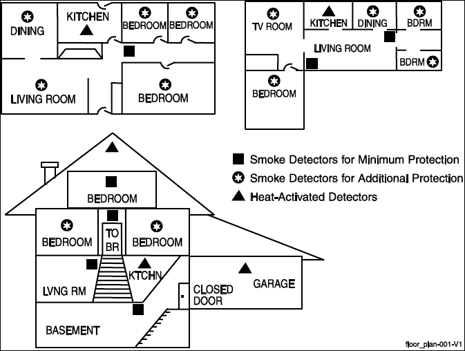
58
National Fire Protection Association
Smoke Detector Recommendations
With regard to the number and placement of smoke and heat detectors, we subscribe to the
recommendations contained in the National Fire Protection Association's (NFPA) Standard #72
noted below.
Early warning fire detection is best achieved by the installation of fire detection equipment in all
rooms and areas of the household. The equipment should be installed as follows: A smoke detector
installed outside of each separate sleeping area, in the immediate vicinity of the bedrooms and on
each additional story of the family living unit, including basements and excluding crawl spaces and
unfinished attics.
In addition, the NFPA recommends that you install heat or smoke detectors in the living room, dining
room, bedroom(s), kitchen, hallway(s), attic, furnace room, utility and storage rooms, basements and
attached garages.
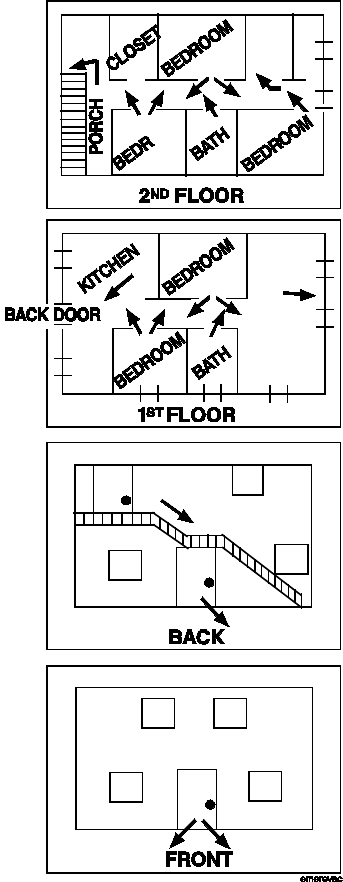
59
Emergency Evacuation
Establish and regularly practice a plan of escape in the event of fire. The following steps are
recommended by the National Fire Protection Association:
1. Position your detector or your interior and/or exterior
sounders so that they can be heard by all occupants.
2. Determine two means of escape from each room. One
path of escape should lead to the door that permits
normal exit from the building. The other should be an
alternative escape, such as a window, should your path
to that door be unpassable. Station an escape ladder
at such windows if there is a long drop to the ground.
3. Sketch a floor plan of the building. Show windows,
doors, stairs and rooftops that can be used to escape.
Indicate escape routes for each room. Keep these
routes free from obstruction and post copies of the
escape routes in every room.
4. Assure that all bedroom doors are shut while you are
asleep. This will prevent deadly smoke from entering
while you escape.
5. Try the door. If the door is hot, check your alternate
escape route. If the door is cool, open it cautiously. Be
prepared to slam the door if smoke or heat rushes in.
6. When smoke is present, crawl on the ground. Do not
walk upright, since smoke rises and may overcome
you. Clearer air is near the floor.
7. Escape quickly; don't panic.
8. Establish a place outdoors, away from your house,
where everyone can meet and then take steps to
contact the authorities and account for those missing.
Choose someone to assure that nobody returns to the
house — many die going back.

60
Regulatory Agency Statements
FEDERAL COMMUNICATIONS COMMISSION (FCC) & INDUSTRY CANADA (IC)
STATEMENTS
The user shall not make any changes or modifications to the equipment unless authorized by the
Installation Instructions or User's Manual. Unauthorized changes or modifications could void the user's
authority to operate the equipment.
CLASS B DIGITAL DEVICE STATEMENT
This equipment has been tested to FCC requirements and has been found acceptable for use. The FCC
requires the following statement for your information:
This equipment generates and uses radio frequency energy and if not installed and used properly, that
is, in strict accordance with the manufacturer's instructions, may cause interference to radio and
television reception. It has been type tested and found to comply with the limits for a Class B
computing device in accordance with the specifications in Part 15 of FCC Rules, which are designed to
provide reasonable protection against such interference in a residential installation. However, there is
no guarantee that interference will not occur in a particular installation. If this equipment does cause
interference to radio or television reception, which can be determined by turning the equipment off
and on, the user is encouraged to try to correct the interference by one or more of the following
measures:
• If using an indoor antenna, have a quality outdoor antenna installed.
• Reorient the receiving antenna until interference is reduced or eliminated.
• Move the radio or television receiver away from the receiver/control.
• Move the antenna leads away from any wire runs to the receiver/control.
• Plug the receiver/control into a different outlet so that it and the radio or television receiver are on
different branch circuits.
• Consult the dealer or an experienced radio/TV technician for help.
INDUSTRY CANADA CLASS B STATEMENT
This Class B digital apparatus complies with Canadian ICES-003.
Cet appareil numérique de la classe B est conforme à la norme NMB-003 du Canada.
FCC / IC STATEMENT
This device complies with Part 15 of the FCC Rules, and RSS-210 of Industry Canada. Operation is
subject to the following two conditions: (1) This device may not cause harmful interference, and (2)
This device must accept any interference received, including interference that may cause undesired
operation.
Cet appareil est conforme à la partie 15 des règles de la FCC & de RSS-210 des Industries Canada. Son
fonctionnement est soumis aux conditions suivantes: (1) Cet appareil ne doit pas causer
d’interférences nuisibles. (2) Cet appareil doit accepter toute interférence reçue y compris les
interférences causant une réception indésirable.
RF EXPOSURE WARNING
The antenna(s) used for this transmitter must be installed to provide a separation distance of
at least 7.8 in (20 cm) from all persons and must not be co-located or operated in conjunction
with any other transmitter except in accordance with FCC multi-transmitter product
procedures.
MISE EN GARDE
Exposition aux Frequences Radio:
L'antenne (s) utilisée pour cet émetteur doit être installée
à une distance de séparation d'au moins 7,8 pouces (20 cm) de toutes les personnes.
IMPORTANT NOTE ABOUT EXTERNAL ANTENNAS
If an external cellular radio antenna is used, the antenna may be installed or replaced ONLY by a
professional installer.
TO THE INSTALLER
The external antenna must not exceed a maximum directional gain (including cable loss) of 3.2 dBi at
850 MHz and 2.3 dBi at 1900 MHz.
61
OWNER'S INSURANCE PREMIUM CREDIT REQUEST
This form should be completed and forwarded to your homeowner's insurance carrier for possible premium credit.
A. GENERAL INFORMATION:
Insured's Name and Address:
Insurance Company: Policy No.:
Lyric Gateway
Other ____________
Type of Alarm: Burglary Fire Both
Installed by: Serviced by:
Name Name
Address Address
B. NOTIFIES (Insert B = Burglary, F = Fire)
Local Sounding Device Police Dept. Fire Dept.
Central Station Name:
Address:
Phone:
C. POWERED BY:
A.C. with Rechargeable Power Supply
D. TESTING:
Quarterly Monthly Weekly Other
E. SMOKE DETECTOR LOCATIONS
Furnace Room Kitchen Bedrooms Attic
Basement Living Room Dining Room Hall
F. BURGLARY DETECTING DEVICE LOCATIONS:
Front Door Basement Door Rear Door All Exterior Doors
1st Floor Windows All Windows Interior Locations
All Accessible Openings, Including Skylights, Air Conditioners and Vents
G. ADDITIONAL PERTINENT INFORMATION:
Signature: Date:
62

63
Limitations of This Alarm System
WARNING!
While this system is an advanced design security system, it does not offer guaranteed protection against
burglary or fire or other emergency. Any alarm system, whether commercial or residential, is subject to
compromise or failure to warn for a variety of reasons. For example:
• Intruders may gain access through unprotected openings or have the technical sophistication to bypass an
alarm sensor or disconnect an alarm warning device.
• Intrusion detectors (e.g. passive infrared detectors), smoke detectors, and many other sensing devices will
not work without power. Battery operated devices will not work without batteries, with dead batteries, or if
the batteries are not put in properly. Devices powered solely by AC will not work if their AC power supply is
cut off for any reason, however briefly.
• Signals sent by wireless transmitters may be blocked or reflected by metal before they reach the alarm
receiver. Even if the signal path has been recently checked during a weekly test, blockage can occur if a
metal object is moved into the path.
• A user may not be able to reach a panic or emergency button quickly enough.
• While smoke detectors have played a key role in reducing residential fire deaths in the United States, they
may not activate or provide early warning for a variety of reasons in as many as 35% of all fires, according to
data published by the Federal Emergency Management Agency. Some of the reasons smoke detectors used
in conjunction with this System may not work are as follows. Smoke detectors may have been improperly
installed and positioned. Smoke detectors may not sense fires that start where smoke cannot reach the
detectors, such as in chimneys, in walls, or roofs, or on the other side of closed doors. Smoke detectors also
may not sense a fire on another level of a residence or building. A second floor detector, for example, may
not sense a first floor or basement fire. Moreover, smoke detectors have sensing limitations. No smoke
detector can sense every kind of fire every time. In general, detectors may not always warn about fires
caused by carelessness and safety hazards like smoking in bed, violent explosions, escaping gas, improper
storage of flammable materials, overloaded electrical circuits, children playing with matches, or arson.
Depending upon the nature of the fire and/or the locations of the smoke detectors, the detector, even if it
operates as anticipated, may not provide sufficient warning to allow all occupants to escape in time to
prevent injury or death.
• Passive Infrared Motion Detectors can only detect intrusion within the designed ranges as diagrammed in
their installation manual. Passive Infrared Detectors do not provide volumetric area protection. They do
create multiple beams of protection, and intrusion can only be detected in unobstructed areas covered by
those beams. They cannot detect motion or intrusion that takes place behind walls, ceilings, floors, closed
doors, glass partitions, glass doors, or windows. Mechanical tampering, masking, painting or spraying of any
material on the mirrors, windows or any part of the optical system can reduce their detection ability. Passive
Infrared Detectors sense changes in temperature; however, as the ambient temperature of protected area
approaches the temperature range of 90° to 105°F, the detection performance can decrease.
• Alarm warning devices such as sirens, bells or horns may not alert people or wake up sleepers if they are
located on the other side of closed or partly open doors. If warning devices sound on a different level of the
residence from the bedrooms, then they are less likely to waken or alert people inside the bedrooms. Even
persons who are awake may not hear the warning if the alarm is muffled from a stereo, radio, air conditioner
or other appliance, or by passing traffic. Finally, alarm warning devices, however loud, may not warn
hearing-impaired people or waken deep sleepers.
• Communication paths needed to transmit alarm signals from a premises to a central monitoring station may
be out of service or temporarily out of service. Communication paths are also subject to compromise by
sophisticated intruders.
• Even if the system responds to the emergency as intended, however, occupants may have insufficient time
to protect themselves from the emergency situation. In the case of a monitored alarm system, authorities
may not respond appropriately.
• This equipment, like other electrical devices, is subject to component failure. Even though this equipment is
designed to last as long as 10 years, the electronic components could fail at any time.
The most common cause of an alarm system not functioning when an intrusion or fire occurs is inadequate
maintenance. This alarm system should be tested weekly to make sure all sensors and transmitters are working
properly.
Installing an alarm system may make one eligible for lower insurance rates, but an alarm system is not a
substitute for insurance. Homeowners, property owners and renters should continue to act prudently in
protecting themselves and continue to insure their lives and property.
We continue to develop new and improved protection devices. Users of alarm systems owe it to themselves and
their loved ones to learn about these developments.

64
Your System Information
Your local Honeywell dealer is the person best qualified to service your alarm system.
Arranging a program of regular service is advisable.
Security Company/Installer:
Name:
Address:
Phone:
DELAY DURATIONS AND ARMING OPTIONS
Exit Delay time
Entry Delay time 1
Entry Delay time 2
NIGHT HOME enabled zones
QUICK ARM enabled? Yes No
SYSTEM USERS
Keep track of authorized system users in the chart below. This record should be kept secure by the
Master User.
User #
User Code
Comment/Description
02
(preset) Master User Can add and modify Users.
Can add, modify, edit and run all Smart Scenes.
47
(preset) Guest The Guest user code can be used to arm the system, but
cannot disarm it unless the system was armed using the Guest
code.
48
(preset) Duress Enter this code if forced to disarm/arm the system under
threat. System appears to behave normally, but silently notifies
alarm monitoring service.
03
04
05
06
07
08
09
10
11
12
13
14

65
SMART SCENES
Name
Voice Command assigned?
Description

66
Z-Wave Devices
Type
Name
Location

67
TWO YEAR LIMITED WARRANTY
Honeywell International Inc., acting through its Security & Communications business (“Seller”), 2 Corporate
Center Drive, Melville, New York 11747 warrants its products to be free from defects in materials and
workmanship under normal use and service, normal wear and tear excepted, for 24 months from the
manufacture date code; provided, however, that in the event the Buyer presents a proper invoice relating to the
purchased product and such invoice bears a date later than the manufacture date, then Seller may at its
discretion, reflect the warranty period as commencing at invoice date. Except as required by law, this Limited
Warranty is only made to Buyer and may not be transferred to any third party. During the applicable warranty
period, Seller will repair or replace, at its sole option and as the exclusive remedy hereunder, free of charge, any
defective products.
Seller shall have no obligation under this Limited Warranty or otherwise if the product:
(i) is improperly installed, applied or maintained;
(ii) installed outside of stated operating parameters, altered or improperly serviced or repaired by anyone other
than the Seller/Seller’s Authorized Service/Repair Center;
(iii) damage is caused by outside natural occurrences, such as lightning, power surges, fire, floods, acts of
nature, or the like; or
(iv) defects result from unauthorized modification, misuse, vandalism, alterations of serial numbers, other causes
unrelated to defective materials or workmanship, or failures related to batteries of any type used in
connection with the products sold hereunder.
Exceptions to Warranty With Respect to Honeywell Products listed below:
Hardwire Contacts and PIRs – Seller warrants parts for hardwire contacts and PIRs in accordance with the terms
of the above limited warranty for a period of five (5) years from the manufacture date code.
EXCLUSION OF WARRANTIES, LIMITATION OF LIABILITY
THERE ARE NO WARRANTIES OR CONDITIONS, EXPRESS OR IMPLIED, OF MERCHANTABILITY, OR FITNESS
FOR A PARTICULAR PURPOSE OR OTHERWISE, WHICH EXTEND BEYOND THE DESCRIPTION ON THE FACE
HEREOF. TO THE FULLEST EXTENT PERMITTED BY LAW, IN NO CASE SHALL SELLER BE LIABLE TO
ANYONE FOR ANY (i) CONSEQUENTIAL, INCIDENTAL, INDIRECT, SPECIAL, OR PUNITIVE DAMAGES ARISING
OUT OF OR RELATING IN ANY WAY TO THE PRODUCT AND/OR FOR BREACH OF THIS OR ANY OTHER
WARRANTY OR CONDITION, EXPRESS OR IMPLIED, OR UPON ANY OTHER BASIS OF LIABILITY
WHATSOEVER, EVEN IF THE LOSS OR DAMAGE IS CAUSED BY SELLER’S OWN NEGLIGENCE OR FAULT AND
EVEN IF SELLER HAS BEEN ADVISED OF THE POSSIBILITY OF SUCH LOSSES OR DAMAGES. Any product
description (whether in writing or made orally by Seller or Seller’s agents), specifications, samples, models,
bulletin, drawings, diagrams, engineering sheets or similar materials used in connection with the Buyer’s order
are for the sole purpose of identifying the Seller’s products and shall not be construed as an express warranty or
condition. Any suggestions by Seller or Seller’s agents regarding use, applications, or suitability of the products
shall not be construed as an express warranty or condition unless confirmed to be such in writing by Seller.
Seller does not represent that the products it sells may not be compromised or circumvented; that the products
will prevent any personal injury or property loss by burglary, robbery, fire or otherwise, or that the products will
in all cases provide adequate warning or protection. Buyer understands that a properly installed and maintained
alarm may only reduce the risk of a burglary, robbery or fire without warning, but it is not insurance or a
guarantee that such will not occur or will not cause or lead to personal injury or property loss. CONSEQUENTLY,
SELLER SHALL HAVE NO LIABILITY FOR ANY PERSONAL INJURY, PROPERTY DAMAGE OR OTHER LOSS
BASED ON ANY CLAIM AT ALL INCLUDING A CLAIM THE PRODUCT FAILED TO GIVE WARNING. However, if
Seller is held liable whether directly or indirectly for any loss or damage with respect to the products it sells,
regardless of cause or origin, its maximum liability shall not in any case exceed the purchase price of the
product, which shall be fixed as liquidated damages and not as a penalty, and shall be the complete and
exclusive remedy against the Seller. Should your product become defective during the warranty, please contact
your installer to facilitate repair or replacement with Seller pursuant to the terms hereof. Seller reserves the right
to replace any defective product under warranty with new, refurbished, or remanufactured product.
For patent information, see www.honeywell.com/patents

Ref: LCP300-L/LCP300-LC
Ê800-21670ÁŠ
800-21670 10/16 Rev A
2 Corporate Center Drive, Suite 100
P.O. Box 9040, Melville, NY 11747
Copyright 2016 Honeywell International Inc.
www.honeywell.com/security