Ademco 8DLGW Harmony Gateway User Manual Lynx R24 Lynx R
Honeywell International Inc. Harmony Gateway Lynx R24 Lynx R
Ademco >
Contents
- 1. Installation Manual
- 2. Quick User Guide
Installation Manual
LyricTM Gateway Installation and Reference Guide
Ref: LCP300-L/LCP300-LC
800-21666 10/16 Rev. A
PLEASE GO TO THE PAGE 34 FOR FCC/IC AGENCY
STATEMENTS
Lyric Gateway Installation and Reference Guide
- 2 -
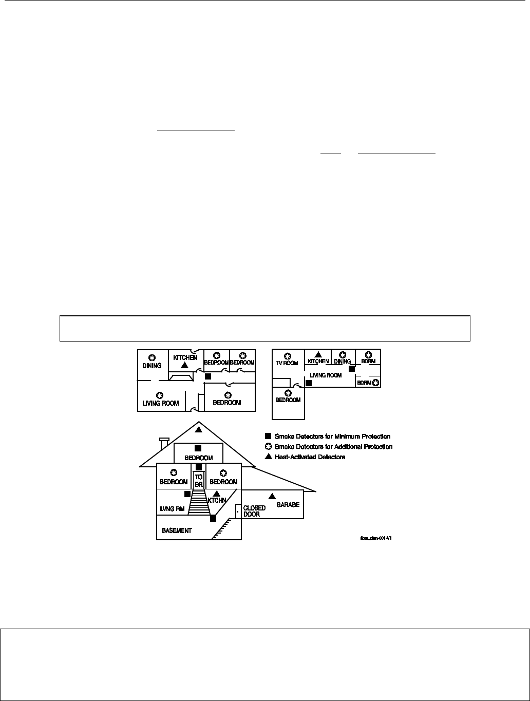
RECOMMENDATIONS FOR PROPER PROTECTION
The Following Recommendations for the location of fire and burglary detection devices help provide proper
coverage for the protected premises.
Recommendations for Smoke and Heat Detectors
With regard to the number and placement of smoke/heat detectors, we subscribe to the recommendations
contained in the National Fire Protection Association's (NFPA) Standard #72 noted below.
• Early warning fire detection is best achieved by the installation of fire detection equipment in all rooms and
areas of the household as follows: For minimum protection a smoke detector should be installed outside of
each separate sleeping area, and on each additional floor of a multi-floor family living unit, including
basements. The installation of smoke detectors in kitchens, attics (finished or unfinished), or in garages is not
normally recommended.
• For additional protection the NFPA recommends that you install heat or smoke detectors in the living room,
dining room, bedroom(s), kitchen, hallway(s), attic, furnace room, utility and storage rooms, basements and
attached garages.
In addition, we recommend the following:
• Install a smoke detector inside every bedroom where a smoker sleeps.
• Install a smoke detector inside every bedroom where someone sleeps with the door partly or completely
closed. Smoke could be blocked by the closed door. Also, an alarm in the hallway outside may not wake up
the sleeper if the door is closed.
• Install a smoke detector inside bedrooms where electrical appliances (such as portable heaters, air
conditioners or humidifiers) are used.
• Install a smoke detector at both ends of a hallway if the hallway is more than 40 feet (12 meters) long.
• Install smoke detectors in any room where an alarm control is located, or in any room where alarm control
connections to an AC source or phone lines are made. If detectors are not so located, a fire within the room
could prevent the control from reporting a fire or an intrusion.
THIS CONTROL COMPLIES WITH NFPA REQUIREMENTS FOR TEMPORAL PULSE
SOUNDING OF FIRE NOTIFICATION APPLIANCES.
Recommendations for Proper Intrusion Protection
• For proper intrusion coverage, sensors should be located at every possible point of entry to a home or
premises. This would include any skylights that may be present, and the upper windows in a multi-level
building.
• In addition, we recommend that radio backup be used in a security system. This will ensure that alarm signals
can be sent to the alarm monitoring station in the event that the communications are out of order (if
connected to an alarm monitoring station).
This Honeywell security system is designed for use with devices manufactured or approved by Honeywell for use with the
system. The security system is not designed for use with any device that may be attached to the system's control or other
communicating bus if Honeywell has not approved such device for use with the system. Use of any such unauthorized device
may cause damage or compromise the performance of the security system and affect the validity of the end user’s Honeywell
limited warranty. When you install devices that have been manufactured or approved by Honeywell, you give the end user
the assurance that these devices have been thoroughly tested to ensure optimum performance when used with this
Honeywell security system.

Lyric Gateway Installation and Reference Guide
- 3 -
Table of Contents
System Features ............................................................................................................................................................................................ 5
Installing the Control .................................................................................................................................................................................... 7
Battery Installation .......................................................................................................................................................................................... 7
Battery Selection ..................................................................................................................................................................................... 7
Installing the Rechargeable Backup Battery ................................................................................................................................. 7
Replacing the Rechargeable Backup Battery ............................................................................................................................... 7
Wall Mounting .................................................................................................................................................................................................. 8
Desktop Mounting .......................................................................................................................................................................................... 9
Replace the Back Plate ......................................................................................................................................................................... 9
Install the Desk Stand ........................................................................................................................................................................... 9
AC Power .......................................................................................................................................................................................................... 10
Wiring Overview ............................................................................................................................................................................................ 10
Make Electrical Connections ............................................................................................................................................................. 10
Communications Modules ........................................................................................................................................................................... 11
Communications Module 24-Hour Standby power ................................................................................................................... 11
Install and Configure Communications Module .................................................................................................................................. 11
Installing the Cellular Module ............................................................................................................................................................. 11
Checking Signal Strength ................................................................................................................................................................... 12
Wireless Zones .............................................................................................................................................................................................. 13
General Information ...................................................................................................................................................................................... 13
Zones .......................................................................................................................................................................................................... 13
Range ......................................................................................................................................................................................................... 13
Transmitters ............................................................................................................................................................................................. 13
House Identification .............................................................................................................................................................................. 13
Transmitter Supervision ...................................................................................................................................................................... 13
Transmitter Input Types ...................................................................................................................................................................... 13
Transmitter Battery Life ...................................................................................................................................................................... 13
RF Transmitter Loop Numbers ......................................................................................................................................................... 14
Mechanics of Programming .................................................................................................................................................................... 15
Navigating Menus .......................................................................................................................................................................................... 15
Touch-screen Display........................................................................................................................................................................... 15
Navigation Keys ..................................................................................................................................................................................... 16
Home Screen ........................................................................................................................................................................................... 16
Security Screen ...................................................................................................................................................................................... 17
Master User Tools Screen ................................................................................................................................................................... 17
Programming .................................................................................................................................................................................................. 18
Enter Installer Programming Mode ................................................................................................................................................. 18
Loading Factory Defaults ........................................................................................................................................................................... 19
Select a Default Configuration ......................................................................................................................................................... 19
Exit Programming Mode ............................................................................................................................................................................. 19
Zone Response Type Definitions ......................................................................................................................................................... 20
General Information ..................................................................................................................................................................................... 20
System Operation ....................................................................................................................................................................................... 22
Key/Touchscreen Operation .................................................................................................................................................................... 22
Panic Key/Icons ............................................................................................................................................................................................. 22
Security Codes ............................................................................................................................................................................................... 22
Installer Code ......................................................................................................................................................................................... 22
Master Code ........................................................................................................................................................................................... 22
Enter/Change the Master Code by Installer ............................................................................................................................... 22
Secondary User Codes ....................................................................................................................................................................... 22
Reset Master Code ............................................................................................................................................................................... 23
Security Code Notes ........................................................................................................................................................................... 23
System Displays ............................................................................................................................................................................................ 24
Zone Status Displays ................................................................................................................................................................................... 24
Audio Alarm Verification (Two-Way Voice Feature) ..................................................................................................................... 25
Activation ................................................................................................................................................................................................ 25
Operator Commands .......................................................................................................................................................................... 25
Event Log ........................................................................................................................................................................................................ 26
Contact ID Event Log Codes ............................................................................................................................................................ 26
Central Station Messages .......................................................................................................................................................................... 27
Testing the System .................................................................................................................................................................................... 28

Lyric Gateway Installation and Reference Guide
- 4 -
Table of Contents (Continued)
Test Modes ...................................................................................................................................................................................................... 28
Testing the System....................................................................................................................................................................................... 28
Armed System Test ..................................................................................................................................................................................... 28
Zone Discovery Mode ................................................................................................................................................................................. 29
Rebooting the System ................................................................................................................................................................................ 29
Programming Default Values ............................................................................................................................................................... 30
Zone Assignment/Alarm Response Type for Configuration 1 ..................................................................................................... 32
Zone Assignment/Alarm Response Type for Configuration 2 .................................................................................................... 33
Zone Assignment/Alarm Response Type for Configuration 3 and 4 ....................................................................................... 34
Zone Response Type Matrix .................................................................................................................................................................. 35
Regulatory Agency Statements ........................................................................................................................................................... 36
Limitations of this System Statement ............................................................................................................................................... 37
Agency Notices ............................................................................................................................................................................................ 38
SIA Quick Reference Guide .................................................................................................................................................................... 39
Specifications ................................................................................................................................................................................................ 39
Glossary .......................................................................................................................................................................................................... 40
Contacting Technical Support ............................................................................................................................................................... 41
Index .................................................................................................................................................................................................................. 42
Summary of Connections Diagram ..................................................................................................................................................... 43
Warranty Information ............................................................................................................................................................ Rear Cover
Lyric™ Lock
This system supports Lyric Lock, an advanced feature designed to keep it functioning optimally. Lyric Lock
capabilities include: the ability to interact with Honeywell and your company’s network for the setup and
programming of system features, support for remote software updates and the ability (when enabled) to
enhance the end user’s security by preventing unauthorized takeover of the system by another monitoring
company.
In the event that the end user wishes to authorize another company to take over the system, the end user may
request that Honeywell remotely disable Lyric Lock. Honeywell will require documentation that the end user
has attempted to contact your company three times and that your company has failed to respond, or failed to
agree to the end user’s request.

Lyric Gateway Installation and Reference Guide
- 5 -
System Features
The Lyric Gateway is a self-contained, rechargeable wireless control/communicator that features easy
installation and usage. A built-in speaker provides voice annunciation of system status along with voice
descriptors of each zone. An internal module allows the controller to communicate with the Central Station via
the Internet or (if installed) Cellular Wireless.
ETL
Lyric Gateway is not intended for UL985 Household Fire applications unless a 24-hour backup
battery (p/n 300-03866-AIO) is installed.
System Features
•
Message Center (for user recorded messages)
•
Voice Announcement of System and Zone Status
•
Ten User-selectable Chime Sounds
• Automatic Stay Arming
•
Night Stay Arming
•
49 User Codes (Installer, Master, Guest, Duress)
•
Panic Functions (Police, Fire, Medical)
•
Programmable Reminders
• Video Camera Control (requires WiFi connection)
• Supports Mobile Devices (Tablet, iPAD, etc.) that duplicate functions of the Lyric Gateway (i.e.; Security,
Web Content Home Automation and Video Control)
Home Automation
•
Integrated Z-Wave Support
•
Control up to 72 Z-Wave Home Automation Devices including:
-
Thermostats (up to 8)
-
Door Locks (up to 6)
- Devices (outlets, switches, lamps/appliances) (up to 60)
-
Garage Doors (up to 4)
-
Water Valves (up to 4)
•
Supports Z-Wave Network Wide Inclusion (NWI) Mode
•
100 programmable Smart Actions
• Up to 150 scheduled events
Zones and Devices
•
4 Panel Panic Zones
•
64 Wireless Zones (5800 and SiX™ Series transmitters)
•
Four Garage Door Zones
•
32 Wireless Buttons (Wireless Key) Zones (5800 and SiX™ Series transmitters)
•
Eight (SiX™ Series) Wireless Keypad Zones
•
12 Temperature Zones
•
Resident Monitor Zone Types
• Built-in Case Tamper
Communication
• ADEMCO Contact ID
• Integrated WiFi Support
•
Cellular (GSM or CDMA) Central Station communication
•
WiFi Central Station communication
•
Ethernet Central Station communication
• Two-way Voice Communication
•
Supports AlarmNet 360
TM
Remote Services

Lyric Gateway Installation and Reference Guide
- 6 -
System Features
(Continued)
System Power
• Primary Power: Plug-in Power Supply, 110VAC to 9VDC, 2.5A output p/n 300-04705V1 (300-4063V1 in
Canada)
• Backup Battery: Rechargeable Nickel-metal Hydride Battery Pack rated at 7.2Vdc. (p/n 300-03864-AIO
or 300-03866-AIO
Alarm Output
•
Built-in Sounder
•
Steady Output for burglary/panic
• Temporal (3) Pulse Output for fire alarms
•
Temporal (4) Pulse Output for carbon monoxide alarms
•
Audio Alarm Verification (AAV)
Programming
•
Options stored in EEROM
• Can be uploaded, downloaded or controlled via AlarmNet 360
TM
using capable Cellular or WiFi
Communications Module
•
Flash Downloading
Other Features
• Exit Error feature (detects difference between an actual alarm and exit alarm caused by leaving a door
open after the exit delay expires)
• Event Log Storage (total 6,000 events)
•
RF Jam Detection
• Advanced Protection Logic™ (APL) (Minimizes the likelihood of the system being disabled before
notification can be sent to the Central Station indicating that the premises have been compromised.)
•
Lyric™ Lock (Customer Retention Logic) Dealer selectable Lockout (anti-takeover) feature
• Dealer/Central Station Messages (requires Total Connect Service)
Lyric Controller Installation and Reference Guide
- 7 -
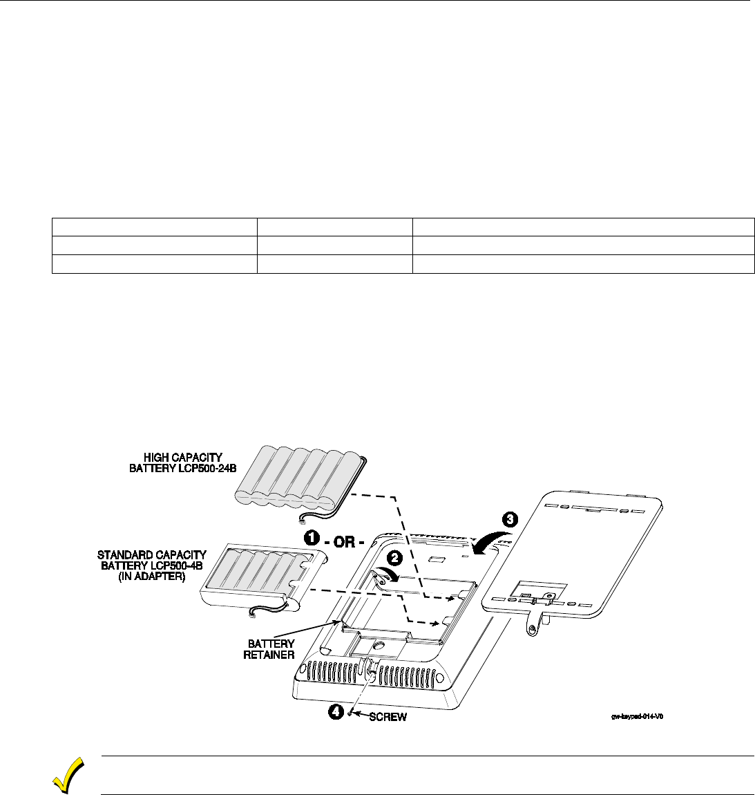
Installing the Gateway
Battery Installation
The Lyric Gateway is equipped with an integral, replaceable, rechargeable battery pack rated at 7.2Vdc. In the
event of an AC power loss, the system is supported by the long life backup battery that is supervised for
connection and for low voltage conditions. If the battery is missing, or a low battery condition is detected, a
“low battery” message is displayed on the smart device and “Alert” will flash red on the Gateway. In addition, a
System Low Battery report is sent to the Central Station. In addition, the system will beep once every 45
seconds to audibly indicate a low battery condition (press any key to stop the beeping). Select the appropriate
battery pack, based on the installation’s requirement, and install the battery pack. Follow the steps and refer to
the figure below to install and connect the battery.
Battery Selection
Select the appropriate battery pack, based on the installation’s requirement, and install the battery pack.
Battery Part Number
Battery StandbyTime
Low Battery Notification
300-03864-AIO
4-hours (minimum)
Approximately 1-hour before battery depletion
300-03866-AIO
24-hours (minimum)
At least 1-hour before battery depletion
Replacing the Rechargeable Backup Battery
1. Insert the battery pack into gateway.
2. Close the hinged battery retainer.
3. Connect the battery pack connector to the receptacle on the gateway.
4. Align the slots on the back of the controller with the hooks on the rear cover/wall mount as shown below.
5. Once attached, insert the screw to secure the rear cover/wall mount.
6. Plug the power supply into a 24-hour, 110VAC unswitched outlet. Upon power-up, the LEDs will flash
alternately.
7. When the power-up sequence is complete, the green Disarmed LED and the green shield will be lit.
Rechargeable batteries may take up to 48-hours to fully charge. The “Low Battery” message
should clear within four hours or by entering Test Mode.
Replacing the Rechargeable Backup Battery
1. When battery replacement is required, at the Master User Tools Menu screen select the “Advanced” icon.
2. Select “Install Backup Battery” and follow the displayed steps to replace the battery or follow the steps
below.
Remove the battery
1. Remove the screw securing the gateway to the rear cover/wall mount (if used).
2. Remove the back case or remove the gateway from the rear cover/wall mount.
Lyric Gateway Installation and Reference Guide
- 8 -
Installing the Gateway
(Continued)
3. Disconnect the battery pack connector from the receptacle on the back of the gateway.
4. Open the hinged battery retainer.
5. Remove the battery pack from the Gateway.
Install the replacement battery
1. Install a replacement battery pack (LCP500-4B [p/n 300-03864-AIO] OR LCP500-24B [p/n 300-03866-
AIO]) into the gateway.
2. Close the hinged battery retainer.
3. Connect the battery pack connector to the receptacle on the gateway.
4. Align the slots on the back of the controller with the hooks on the rear cover/wall mount as shown below.
5. Once attached, insert the screw to secure the rear cover/wall mount.
6. Plug the power supply into a 24-hour, 110VAC unswitched outlet. Upon power-up, the LEDs will flash
alternately.
7. When the power-up sequence is complete, the green Disarmed LED and the green shield will be lit.
NOTE: If a Cellular Communication Module is being installed, verify the module’s signal strength before
selecting a final mounting location. Refer to Checking the Signal Strength in the Communications
Module section.
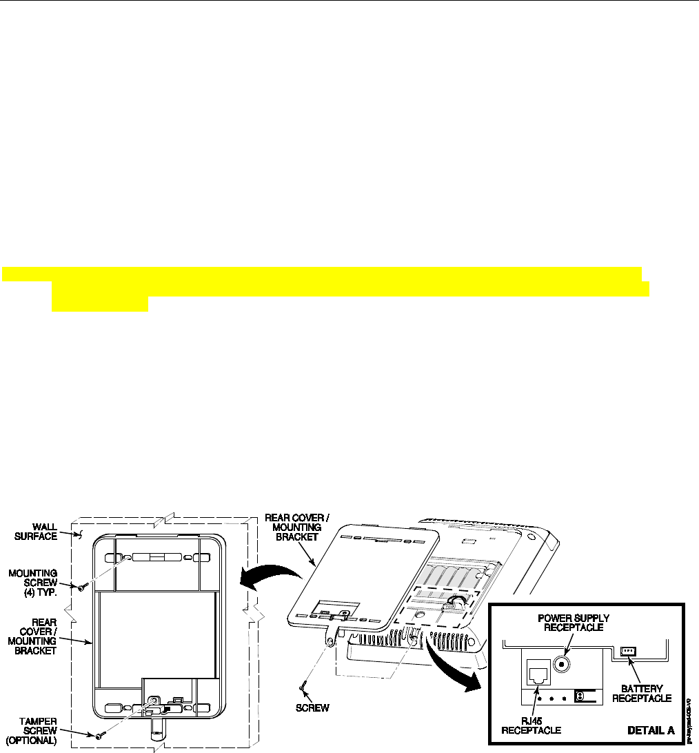
Wall Mounting
NOTE: When selecting a location for the Lyric Controller, be sure to provide a separation of at least 10 feet
between 2.4GHz devices such as Wi-Fi Routers/Access Points.
For wall mounting follow the steps and refer to the figure below.
1. Feed the field wiring through the appropriate openings in the wall mount.
2. Attach the wall mount to a sturdy wall using the four provided screws.
3. If required, install an additional mounting screw in the case tamper.
4. Align the slots on the back of the controller with the hooks on the wall mount as shown below.
5. Once attached, insert the screw to secure the Lyric to the wall mount.
Lyric Gateway Installation and Reference Guide
- 9 -
Installing the Gateway (Continued)
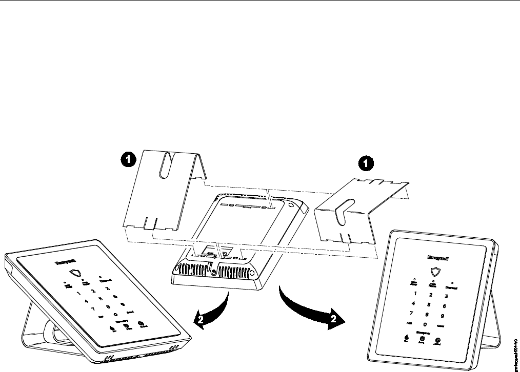
Desktop Mounting
NOTE: When selecting a location for the Lyric Gateway, be sure to provide a separation of at least 10 feet
between 2.4GHz devices such as Wi-Fi Routers/Access Points.
The desk Stand can be installed in two positions that provide a viewing angle of 30 degrees or 60 degrees.
Follow the steps and refer to the figures below.
Install Desk Stand
1. Align the slots on the back of the gateway with the hooks on the desk stand as shown below.
2. Insert the stand into the slots on the rear case to provide the desired viewing angle and slide up to lock in
place.
Lyric Gateway Installation and Reference Guide
- 10 -
Installing the Control
(Continued)
AC Power
The Lyric Gateway is powered by a 110VAC, 60 Hz/9 Volt DC, 2.5 Amp Plug-in Power Supply, 300-04705V1
(300-04063V1 in Canada). Refer to the wiring table below for wire gauge and length.
Use only the 300-04705V1 (300-04063V1 Canada) Power Supply. Do not plug the power supply
into the AC outlet until after all wiring connections have been made.
Wiring Overview
The following summarizes the electrical connections associated with the Lyric Gateway. Follow the steps and
refer to the figure below when making connections. Refer to the Summary of Connections diagram for
additional information.
Make Electrical Connections
1. Temporarily hang the controller from the hook on the wall mount.
2. Connect the male end of the receptacle on the Gateway.
3. Align the slots on the back of the Gateway with the hooks on the rear cover/mounting bracket.
4. Once attached, insert the screw to secure the Gateway to the rear cover/mounting bracket .
5. Connect the flying leads of the provided power supply cable to the + and – terminals on the power supply
(p/n 300-04705V1 or 300-04063V1).
6. Plug the power supply into a 24-hour, 110VAC unswitched outlet. Upon power-up, the “System Standby!”
screen will be displayed.
WIRING TABLE
Maximum Distance Between
Power Supply and Controller
Wire Gauge
Up to 8 feet (2.44 m)
# 22
Up to 13 feet (3.96 m)
# 20
Up to 20 feet (6.1 m)
# 18
Lyric Gateway Installation and Reference Guide
- 11 -
Installing the Gateway (Continued)
The LYRIC-CDMA Communications Module is only available in the continental United States,
Alaska and Hawaii.
Communication Modules
The Lyric Gateway supports Central Station reporting using wireless/cellular and WiFi communications devices.
They also support upload/download programming capability via the Internet. This allows site maintenance
independent of Central Station monitoring, and modification to sites globally via the Internet. Refer to the Quick
Installation Guide (p/n 800-21668) for information regarding programming and registration. Additionally, an
internal Z-Wave module allows the Lyric Gateway to support Home Automation functions. (refer to the Gateway
Guide (p/n 800-16078 for additional information.) The controllers are compatible with the following AlarmNet
Communication Modules:
Model
Description
LYRIC-3G
GSM Cellular Communications Module
LYRIC-CDMA
CDMA Cellular Communications Module
Communications Module 24-Hour Standby Power
If 24-hour standby is required, the Super High Capacity battery (p/n 300-03866-AIO) must be installed.
RF Exposure
WARNING: The Lyric Gateway must be installed to provide a separation distance of at least 7.8
in (20 cm) from all persons and not co-located or operated in conjunction with any other
transmitter except in accordance with FCC multi-transmitter product procedures.
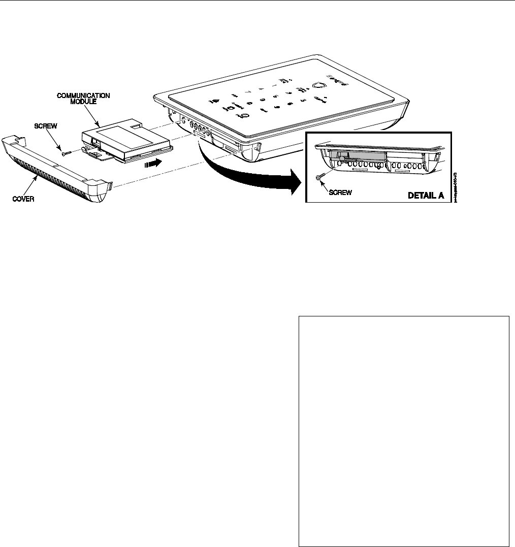
Install and Configure Communication Module
Follow the steps and refer to the figure below to install the Communications Module.
Installing the Cellular Communications Module
1. At the the Master User Tools Menu Programming screen select “Advanced”.
2. Select “Install Cellular Module” and follow the prompts displayed on the smart device or follow the steps
below.
3. Remove Gateway upper cover (bezel).
4. Remove the screw securing the module to the Gateway (if installed).
5. Remove the existing Cellular Communications Module (if installed).
6. Install the Cellular Communications Module into the Gateway.
7. Ensure that the Communications Module is properly seated into the Gateway and secure the module with
the provided screw (if required).
8. Insert the cover (bezel) into the Gateway
9. Slide the side cover (bezel) down to lock it in place and secure the Communications Module.
10. Select OK to complete the installation.
NOTE: The Communication Path will be dynamically adjusted when a Cellular Communication Module is
installed or removed.
11. Enable the Communications Module, configure alarm reporting and module supervision and register the
device. Refer to the “Program Communicator” and “Communications Diagnostics” sections in the
Programming Guide (p/n 800-18077). OR Log on to the AlarmNet 360TM website (http://alarmnet360.com).
The Communications Module must be registered with AlarmNet 360TM before downloading or
alarm reporting can take place.
Lyric Gateway Installation and Reference Guide
- 12 -
Installing the Gateway (Continued)
Communication Modules
Checking Signal Strength
When choosing a suitable mounting location, check the communications module’s signal strength to
ensure proper operation. For most installations, using the module’s internal antenna, mounting the
Lyric Gateway as high as practical, and avoiding large metal components provides adequate signal
strength for proper operation. To check signal strength, perform the following test.
Check Signal Strength
1. With the System in the Installer Programming mode,
select the “Comm. Diagnostics” button and then select
the “Cellular Information” button. The Cellular
Information will be displayed. The signal strength is
displayed (in dBm) as RSCP if the Lyric-3G module is
operating on the 3G Network or RSSI if the module
Lyric-3G module is operating on the 2G Network and for
the Lyric-CDMA module.
2. Compare the displayed RSCP or RSSI number to the
correct Signal Strength Guide at right to ensure
adequate signal strength. If necessary, relocate the
Controller to obtain better signal strength (select
“Cellular Information” again to refresh the reading).
3. If adequate signal strength cannot be achieved, External
Antenna Kit model Cell-ANTST should be used.
Lyric -3G Signal Strength
RSCP (3G)
Good .......................................... -20 to -90 dBm
OK ................................................ -91 to -100 dBm
Marginal ................................... -101 to -106 dBm
Bad ........................................... -107 to -120 dBm
RSSI (2G)
Good ........................................... -20 to -89 dBm
OK ................................................ -90 to -98 dBm
Marginal .................................. -99 to -104 dBm
Bad .......................................... -105 to -120 dBm
Lyric -CDMA Signal Strength
RSSI
Good ........................................... -20 to -90 dBm
OK ................................................ -91 to -100 dBm
Marginal ................................... -101 to -106 dBm
Bad .......................................... -107 to -120 dBm

Lyric Controller Installation and Reference Guide
- 13 -
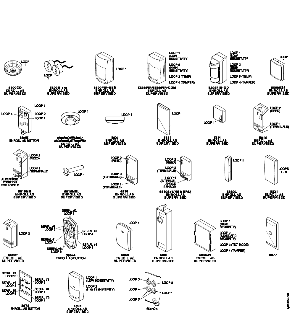
Wireless Zones
General Information
Zones
The Lyric Gateway supports up to 64 total wireless zones using 5800 and SiX™ Series transmitters, and wireless
keys.
Range
The built-in RF receiver can detect signals from wireless transmitters within a nominal range of 200 feet.
Transmitters
5800 and SiX™ Series transmitters have built-in serial numbers that must be entered into the system via
AlarmNet 360TM. Each transmitter's zone number is also programmed into the system in the “Zones”
programming section. Some transmitters, such as the 5816 can support more than one "zone" (referred to as
loops or inputs). On the 5816, for example, the wire connection terminal block is loop 1; the reed contact is loop
2. Each loop must be assigned a different zone number.
For 5800 Series wireless keys such as the 5804E, 5834-4 and 5878, you must assign a unique zone number to
each individual button used on the transmitter. Each button on the transmitter also has a pre-designated loop
or input number, which is automatically displayed.
ETL
The 5816 Transmitters do not have EOL supervision of their loop wiring, which must not exceed 3
feet.
The 5800PIR-OD, 5800SS1, 5804E, 5814, 5821, 5877 and 5878 wireless transmitters have not been
evaluated by ETL.
House Identification
If a RF House ID (RF House Code) is required to establish proper communication, the same two-digit code (01–
31) must be programmed in the Lyric, and the device. Refer to the “System Type” programming section in the
Lyric Gateway Programming Guide (p/n 800-18077). An RF House ID is not necessary for 5800 Series
transmitters and the entry should be left at “0” (default) in those cases.
Transmitter Supervision
With the exception of some transmitters/keypads that may be carried off-premises (5804E, 5834-4 and
SiXFOB), each transmitter is supervised by a check-in signal that is sent to the receiver at 70–90 minute
intervals. If at least one check-in is not received from each supervised transmitter within a 12-hour period, the
"missing" transmitter zone number(s) and "Supervision" will be displayed. The supervision for a particular
transmitter in the system that may also be carried off the premises may be turned off by entering it as an
“Unsupervised” type. For additional information, refer to the “Zones” programming section in the Lyric
Gateway Quick Installation Guide (p/n 800-21668). 5800 and SiX™ Series transmitters have built-in tamper
protection and will annunciate as a fault condition if covers are removed. In Canada the RF supervision period
is 3-hours for Fire zones and 12 hours for all other zone types.
Transmitter Input Types
Each transmitter has one or more unique factory-assigned input (loop/5800 Series or service/SiX™ Series) ID
codes. Each of the inputs requires a programming zone (e.g., a 5804E's four inputs require four button zones).
Transmitters can be entered as one of the following types (see transmitter’s instructions for appropriate
Supervision type):
Type
Description
Supervised
Sends periodic check-in signals, as well as fault, restore, and low battery signals. The
transmitter must remain within the receiver's range.
Unsupervised
Sends all the signals that the Supervised type does, but the controller does not supervise the
check-in signals. The transmitter may therefore be carried off-premises.
Button
Sends only fault signals. Do not send low battery signals until being activated. The
transmitter is unsupervised and may be carried off-premises.
Transmitter Battery Life
• Batteries in the wireless transmitters may last from 4–7 years, depending on the environment, usage, and
the specific wireless device being used. Factors such as humidity, high or low temperatures, as well as large
swings in temperature may all reduce the actual battery life in a given installation. The wireless system can
identify a true low battery situation, thus allowing the dealer or user of the system time to arrange a change
of battery and maintain protection for that point within the system.
• Button-type transmitters should be periodically tested for battery life. The 5804E, 5834-4, 5878 and SiXFOB
button transmitters have replaceable batteries.
Lyric Gateway Installation and Reference Guide
- 14 -
Wireless Zones
(Continued)
RF Transmitter Loop Numbers
(Refer to this information when programming 5800 Series transmitters)
The following illustration shows the compatible transmitters, their associated input types and loop designations.
Notes: (1) The 5806W3 smoke detector must be used in SIA applications.
(2) Button type devices send only fault and low battery signals; no restore or check-in signals.
Supervised RF devices send periodic check-in signals, faults, restore and low battery signals.
(3) The 5804E and 5834-4 encrypted (High-Security) devices must be activated while the system is in
Go/No-Go Test Mode. Refer to the transmitter’s Installation Instructions for complete details. The
system will confirm the enrollment of the encrypted device by beeping two times.
(4) The 5800PIR-OD, 5800SS1, 5804E, 5814, 5821, 5877, and 5878 wireless transmitters have not been
evaluated by ETL.
Lyric Controller Installation and Reference Guide
- 15 -
Mechanics of Programming
Navigating
Gateway Keypad
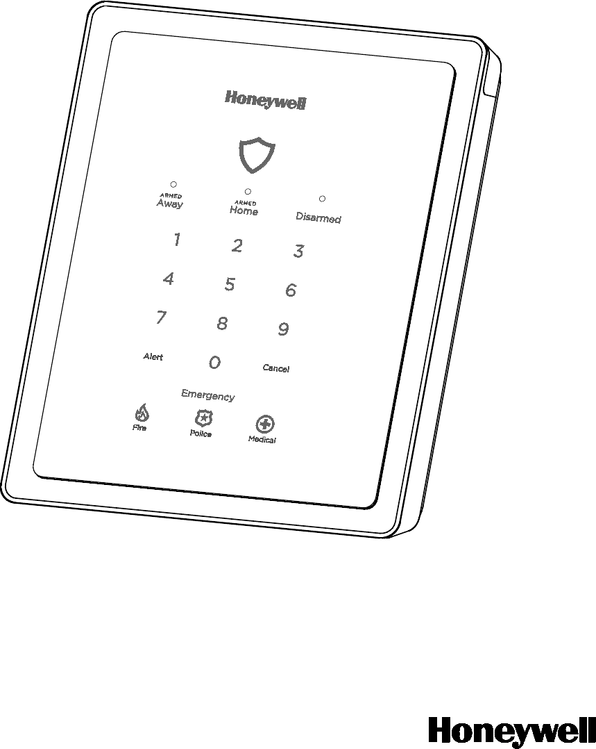
Gateway’s keypad can be used for Basic Security Functions. The keypad provides a number of functions and
indicators. The System Status Shield is lit Green when the system is ready or flashes Red when it is not. When
the system is armed the System Status Shield is lit Red. Refer to the table below for additional indications and
functions. Additional functions are available via the My Home or Total Connect App or the associated websites.
LYRICTM Gateway
Key
Description
System Status Shield – System status is
displayed when the shield is lit as follows:
Green (steady) – Ready to Arm
Red (steady) – System is Armed
Red (slow flash) – Entry/Exit delay countdown
Red (rapid flash) – System is in Alarm
White (steady) – Waiting for User Code entry
ARMED
Away
Arm gateway in Away mode (LED steady red
when selected)
ARMED
Home
Arm gateway in Home mode (LED steady red
when selected)
Disarmed Disarm Gateway (LED flashes green until code
is entered, then turns steady green)
Alert Flashes red when an alert condition exists.
Select to hear condition
Cancel
Cancel User Code entry or Emergency
(Flashes white during an emergency)
Emergency Activates Emergency keys
Fire key -
Initiates panic fire alarm within 5
seconds of activation.
Police key -
Initiates panic police alarm within
5 seconds of activation
Medical key -
Initiates panic medical alarm
within 5 seconds of activation
Gateway Menu Mode
Entering the Master User Code or Installer Code on the Gateway keypad will provide access to Menu Mode.
Enter Menu Mode: Enter Master User or Installer Code + 1 1. The system will announce the menu options based
on the code that was entered.
Code Entered
Menu Option (System Annoucement)
Master User (1234)
Press 20 to delete all enrolled MyHome apps
Press 21 to enter MyMome app Enroll Mode
Press 31 to enter Access Aoint mode
Installer (4112)
Press 31 to enter Access Point mode
Press 51 to enter Go/No-Go Test mode
Lyric Gateway Installation and Reference Guide
- 16 -
Mechanics of Programming (Continued)
Touch-screen Display
The MyHome Gateway App is used to display screens on the smart device touch-screen. Variable
icons and text are displayed on “screens”. The screen displays status icons and associated text, the
current time and date, system status information and menu choices. The Menu area includes a list of
commands, or choices that apply to the current selection. The status area provides information
about various system events and colored text also provides an indication of system status. A “Home
Screen” is displayed whenever the App is opened.
Navigation Keys
Navigating through the screens is accomplished by lightly touching the icons or menu items on the smart device
touch-screen. Once activated, the Gateway advances to the next screen. Selecting the “” key or the “Home”
(cancel) key will return you to the previous screen or the home screen (as applicable) at any time. By touching
(selecting) an icon or key the system, depending on the function, advances to another screen, toggles between
options or scrolls through multiple options that can be selected. The system provides a prompt when a specific
input is required.
Note: You may find it convenient to adjust the volume setting before entering the Program Mode. This will allow
you to clearly hear the feedback announcements or system beeps from the system’s built-in speaker. To
adjust the volume, select “Settings” icon on the Home screen. Adjust the volume using the slide displayed
on the Settings screen and then select “Save” to accept.
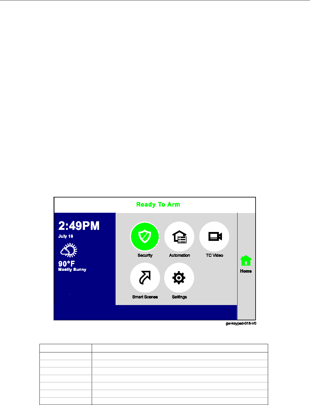
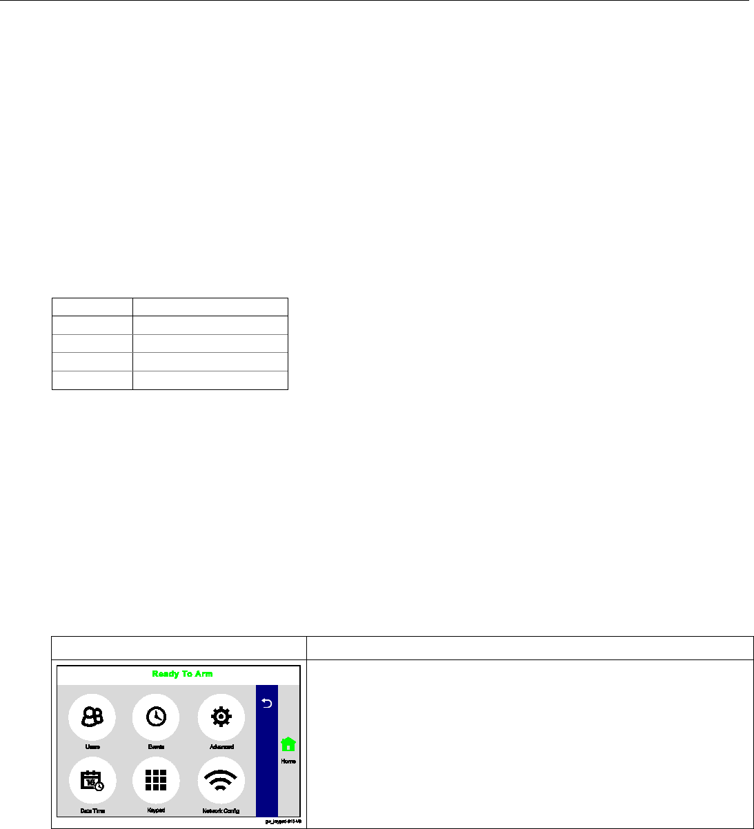
Home Screen
System Status is displayed at the top of screen. In addition to the system status, the Home Screen displays the
current date and time and Security, Automation, TC Video, Smart Scenes and Settings icons. When Total
Connect Services are connected and web content is enabled the current weather forecast and a 5-Day Forecast
button.
Gateway Home Screen with Total Connect Services
Icon
Function
Security
Provides access to Security Screen
Automation
Provides access to Automation Screen
TC Video
Provides access to Video Screen
Smart Scenes
Provides access to Smart Scenes Programming Screen
Settings
Provides access to System Settings Screen
5-Day Forecast
Provides access to local 5-Day Weather Forecast Screen
Weather
Provides local forecast and severe weather alerts
Lyric Controller Installation and Reference Guide
- 17 -
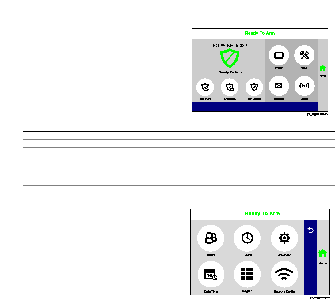
Mechanics of Programming (Continued)
Navigating Menus
Security Screen
System Status is displayed at the top of each screen and
the time and date are displayed at the top left side of
the Security Screen. The Security Screen displays the
system status and selection “icons”. The displayed pages
and options
may vary slightly depending upon the
devices and services that are installed in or connected
to the system.
Security Screen
Selection
Function
Arm Away
Used to Arm the system in Away mode.
Arm Home
Used to Arm the system in Home mode.
Arm Custom
Used to Arm the system in Custom mode.
System
Provides information about system status.
Tools
Provides access to Installer and User Programming Menus (Master User Code required for
access).
Message
Provides access to Message Center.
Zones
Provides access to Zone information and options.
Master User Menu Screen
The Master User Menu screen
provides access to the
User configurable features
. Entering the Master User
Code is required to access the User Tools Menu.
Master User Menu Screen
Lyric Gateway Installation and Reference Guide
- 18 -
Mechanics of Programming (Continued)
Programming
If the system is Armed or in Alarm, the Tools icon will not be functional. The system must first
be disarmed.
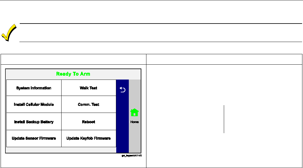
Master User Features
SCREEN
ACTION
Master User Menu Screen
1. Select the “Security” icon.
2. Select “Tools” icon.
3. Enter the Master User Code 1234 on the displayed
keypad.
4. Select one of the following options:
System Information
Install Cellular Module
Install Backup Battery
Update Sensor Firmware
Walk Test
Comm. Test
Reboot
Update Keypad Firmware
5. The system advances to the screen for the selected
option.
Exit Programming Mode
1. Select the “” key to exit the current screen OR select the Home key to return to the Home Screen.

Lyric Controller Installation and Reference Guide
- 19 -
Zone Response Type Definitions
General Information
During programming, you must assign a zone type to each zone, which defines the way in which the system
responds to faults in that zone. Zone types are defined below.
Type
Function
Characteristics
Not Used
Used to program a zone that is not used.
• None
Entry/Exit 1
(Burglary)
Usually assigned to sensors or contacts on
primary entry and exit doors.
• Entry delay #1 is programmable.
• Exit delay is independently programmable.
• Exit and entry delays when armed in Away, Stay or Night
Stay mode.
• No entry delay when armed in Stay or Away Instant modes.
• Exit delay regardless of the arming mode selected.
Entry/Exit 2
(Burglary)
Usually assigned to sensors or contacts on
secondary entry and exit doors that might
be further from the keypad (typically used
for a garage, loading dock, or basement
door).
•
Entry delay #2 is programmable.
• Exit delay is independently programmable.
• Secondary entry delay, if armed in the Away or Stay mode.
• No entry delay when armed in the Stay Instant or Away
Instant mode.
•
Exit delay begins regardless of the arming mode selected.
Perimeter
(Burglary)
Usually assigned to all sensors or contacts
on exterior doors and windows
• Instant alarm, when armed in Away, Stay, Stay No Delay,
Night Stay or Away Instant mode.
Interior, Follower
Usually assigned to a zone covering an area
(i.e.: foyer, lobby, or hallway) that must be
passed upon entry (after faulting the
entry/exit zone) to reach the keypad.
Provides an instant alarm if the entry/exit
zone is not violated first, and protects an
area in the event an intruder has hidden on
the premises before the system is armed, or
gains access through an unprotected area.
•
Delayed alarm (using the programmed entry/exit time) if
entry/exit or interior-with-delay zone is faulted first.
• Instant alarm in all other situations.
• Active when armed in Away or Away Instant mode.
• Bypassed automatically when armed in Stay, Night Stay or
Stay Instant mode.
Trouble by Day/
Alarm by Night
Usually assigned to a zone that covers a
sensitive area (i.e.: stock room, drug supply
room, etc.) It can also be used on a sensor or
contact in an area where immediate
notification of an entry is desired.
• Instant alarm, when armed in Away, Stay, Night Stay , Stay
Instant, or Away Instant (night) mode.
• Provides a latched trouble sounding from the keypad and, if
desired, a Central Station report when disarmed (day).
24-hour Silent
Alarm
Usually assigned to a zone containing an
Emergency button (silent emergency).
•
Sends a report to the Central Station but provides no keypad
display or sounding.
• In disarmed state sends a report to the Central Station
displays "Not Ready to Arm" on the keypad and “Away”,
“Stay” and “Tools” buttons are disabled.
24-hour Audible
Alarm
Usually assigned to a zone containing an
Emergency button (audible emergency).
• Follows sounder timeout
• Sends a report to the Central Station, and provides alarm
sounds at the keypad.
24-hour
Auxiliary
Alarm
Usually assigned to a zone containing a
button for use in personal emergencies or
to a zone containing monitoring devices
(i.e.: water or temperature sensors, etc.).
• Sends a report to the Central Station and provides an alarm
sound at the keypad. (There is no keypad timeout.)
Silent Burglary
Usually assigned to sensors or contacts on
exterior doors and windows where sirens are
NOT desired.
• Instant alarm, with No audible indication when armed in the
Away, Stay, Stay No Delay, Night Stay, or Away Instant mode.
• Report sent to the Central Station.
Local Alarm Usually assigned to a zone containing an
Emergency button (audible emergency).
• Follows sounder timeout.
• Provides alarm sounds at the keypad.
• No reports to the Central Station.
Interior with Delay
Provides entry delay (using the programmed
entry time), if tripped when the controller is
armed in the Away mode. Bypassed when the
controller is armed in the Stay or Stay Instant
mode.
• Entry delay #1 (with programmed entry time) when armed in
the Away mode.
• Entry delay begins whenever sensors in this zone are
violated, regardless of whether an entry/exit delay zone was
tripped first.
• No entry delay when armed in the Away Instant mode.
•
Exit delay regardless of the arming mode selected.
24-hour Carbon
Monoxide Monitor
Can be assigned to any wireless zone with a
carbon monoxide detector. This zone type is
always active and cannot be bypassed.
• Local keypad and detector will sound when this zone type is
alarmed. (Pulse Temporal 4).
Trouble
Used with Other response type.
• The system will provide a trouble sounding from the keypad
(and a Central Station report, if desired).
Fire No
Verification
Can be assigned to any wireless zone used
as a fire zone. This zone type is always
active and cannot be bypassed.
• Alarm sound will pulse (Temporal Fire) when this zone type is
alarmed.

Lyric Gateway Installation and Reference Guide
- 20 -
Zone Response Type Definitions (Continued)
Type
Function
Characteristics
Fire with
Verification
Can be assigned to any wireless zone used
as a fire zone. Fire with verification is
available with smoke detector device type. It
cannot be used with heat detectors,
combination heat/smoke detectors or fire
pull stations. This zone type is always active
and cannot be bypassed.
•
Alarm sound will pulse (Temporal Fire) when this zone type is
alarmed and the alarm has been verified.
• System verifies alarm by delaying reporting and alarm
sounding for 30 seconds after alarm is detected. If the zone
remains faulted after 30 seconds a fire alarm is provided. If
any other fire zone is faulted during the 30 second delay
window a fire alarm is immediately provided for that zone.
An alarm for original fire zone will also be provided, if that
zone is still faulted. If there are no fire alarms after the 30
second delay expires, the system will open a 60 second
window. If any fire zone is faulted during that window a fire
alarm will immediately be provided for that zone.
Arm–Stay
Special-purpose zone type used with 5800
and SiX™ Series wireless keys.
• Exit delay regardless of the arming mode selected.
• System is armed in the Stay mode when the zone is
activated.
Arm–Away
Special-purpose zone type used with 5800
and SiX™ Series wireless keys.
• System is armed in the Away mode when the zone is
activated.
Disarm
Special-purpose zone type used with 5800
and SiX™ Series wireless keys.
• Disarms the system when the zone is activated.
No Alarm
Response
Assigned when no-alarm response is required.
• No reports to the Central Station.
• No keypad sounding or chime and no display on screen.
•
System can still be armed.
Monitor
Can be assigned to any wireless zone used
for asset protection. Works as a dynamic
monitor of a zone fault/trouble (not alarm).
• Reports to the Central Station, if enabled.
• Fault/restore events are logged by the system.
• Activity Zone No. and Zone Descriptor displayed on LCD.
• Restore will be stored in event log.
• No keypad sounding or chime.
•
System can still be armed.
General Monitor
Assigned sensors or contacts on doors and
windows or asset protection within the
premises. Used to track activity of the
occupant and alert occupant of the activity
of others.
• No reports to the Central Station.
• Fault/restore events are logged by the system.
• Monitors entry into a monitored area. Activates a one-time
announcement when faulted.
•
Activity Zone No. and Zone Descriptor displayed on LCD.
General
Response
Assigned sensors or contacts on doors and
windows or asset protection within the
premises. Used to track activity of the
occupant and alert occupant of the activity
of others.
• No reports to the Central Station.
• Fault/restore events are logged by the system.
• Monitors entry into a monitored area. Activates a zone
announcement when faulted.
• Activity Zone No. and Zone Descriptor displayed on LCD.
• System re-triggers audible sounding every ten seconds until
acknowledged.
Resident Monitor
Used to monitor a resident in an area
deemed to be dangerous by a caregiver.
• No reports to the Central Station.
• Monitors entry into a monitored area. Activates a zone
announcement when faulted.
• Activity Zone No. and Zone Descriptor displayed on LCD.
•
Fault/Restore events are not logged by the system.
Resident
Response
Used to monitor a resident in an area
deemed to be dangerous by a caregiver.
Requires acknowledgement by caregiver.
•
No reports to the Central Station.
• Monitors entry into a monitored area. Activates a zone
announcement when faulted.
• Activity Zone No. and Zone Descriptor displayed on LCD.
• System re-triggers audible sounding every ten seconds until
acknowledged (Off sequence or wireless key).
•
Fault/Restore events are not logged by the system.
Garage
(Burglary)
Assigned to Automatic Garage Door
applications. Provides a status of the garage
door close/open real time state.
• Associated With Entry Delay #2 Programmed Time.
• Exit delays when armed in Away, Stay or Night Stay mode.
• No Entry Delay when armed in Away or Stay Instant modes.
• System can be armed with zone in the faulted state. When the
zone is closed it will automatically be inclusive within
protection points. If the point is subsequently violated, it will
initiate an alarm.
Garage Monitor
Assigned to Automatic Garage Door
applications. Provides a status of the garage
door close/open real time state.
• Can be assigned to any wireless zone used for automatic
“Garage Door” Open/Close status.
• Will not initiate an alarm condition on the controller.
• When zone is in the open state will display “FAULT.”
• Does not report alarms to Central Station.
• Zone will chime if enabled.
•
System can be armed if this zone type is in fault.
Lyric Controller Installation and Reference Guide
- 21 -
System Operation
Key/Touchscreen Operation
Touchscreen icons displayed on the Smart Device allow the user to arm and disarm the system, and perform
other system functions, such as bypassing zones. Zone and system conditions (alarm, trouble, bypass) are
displayed on the LCD. When an alarm occurs, the Gateway and Smart Device (if installed) will sound, and the
zone(s) in alarm will be displayed. Pressing any key will silence the keypad sounder for 10 seconds (only once).
Disarming the system will silence both console and external sounders. When the system is disarmed, any zones
that were in an alarm condition during the armed period will be displayed (memory of alarm). To clear this
display, simply repeat the disarm sequence by selecting ”Disarmed” and entering the Security Code. The
console also features chime annunciation, and three panic key icons for silent, audible, Fire or Medical
emergency alarms. These keys can notify the Central Station of an alarm condition, if that service is connected.
Panic Key/Icons
There are three panic keys that are active (if programmed) when the “Emergency” or any of the keys is selected
for approximately five seconds. The panic key screen will timeout if a selection is not made within ten seconds.
The keys can be used to manually initiate alarms and send a report to the Central Station. Each can be
individually programmed for 24-hour silent, audible, personal or fire emergency responses. The panic function is
activated when the respective keys is pressed. The panic functions are identified by the system as follows:
Zone
Function
995
Fire Emergency
996
Medical Emergency
998
Local Alarm
999
Police Emergency
Important: For the silent panic functions to be of practical value, the system must be connected to a Central
Station.
Security Codes
Installer Code
The installer programs the 4-digit Installer Code initially as part of the programming procedure. The
factory default Installer Code is 4-1-1-2, but may be changed in the Installer Code programming field.
The Installer Code is the only code that allows entry into Installer Programming mode.
Master Code
In normal operation mode, the Master (Security) Code is used to enter the 4-digit User Security Codes and enter
the Master User Tools Menu mode.
Enter/Change the Master Code by Installer.
The factory default Master Code for the Lyric Gateway is set to 1-2-3-4. The Master Code is used to enter the 4-
digit User Security Codes.
SCREEN
ACTION
1. After entering the Master User Menu screen, select the “Users”
icon. The system displays the User Code Programming screen.
2. Select “Master”, then select “Edit”.
3. Enter a new 4-digit Master (Security) Code on the displayed
keypad. The system displays the new code on the left side of the
screen.
4. Select “Done” when you are finished.
5. The system returns to the Master Code Programming screen.
Secondary User Codes
In normal operation mode, the Master (Security) Code can be used to assign up to 46 secondary 4-digit security
codes, including a Guest Code and a Duress Code. The Master Code can also be used to individually remove
secondary codes from the system. Refer to the Lyric Gateway User Manual for additional information.

Lyric Gateway Installation and Reference Guide
- 22 -
System Operation
Reset Master Code
1. After Entering the Programming Mode, select “Users” from the Master User screen menu.
2. Select “Master” followed by “Edits’ to reset the Master User Code.
3. Select “User Code”.
4. Enter a new Master Code on the displayed keypad, then select “Done”. The system returns to the previous
screen.
5. Select “Save”
6. If confirmed, the Master Code will be reset back to “1-2-3-4”. This will be logged in the System Event Log as
“User: 1 Reset Master Code, E655”. The system returns to the second page of the Installer Programming
Tools menu.
OR
If the reset failed, the system will display: “Command Failed. Unable to Reset Master Code”. This will only
occur if the code 1-2-3-4 has been assigned to another User in the panel.
Security Code Notes
• The Master and Secondary security codes permit access to the system for arming, disarming,
etc.
• The Installer Code can disarm the system only if it was used to arm it. In addition, the Installer
Code cannot disarm the system if it was armed by pressing and holding a Quick-Arm button.
• The Guest Code can disarm the system only if it was used to arm it. In addition, the Guest Code
cannot disarm the system if it was armed by pressing and holding a Quick-Arm button.
• Duress code sends a special code to the Central Station when used to perform any system
operation. Instruct users to be careful not to use this code for normal usage.
• Opening/closing reports are sent for the Installer Code, with the appropriate subscriber
number. Master Code and secondary user codes are sent as User No. 2 and 3-48 respectively, in
Contact ID® format (with the appropriate user number).
Important Security Notice
Please inform the User about the security importance of their wireless key (key fob), and what to do
if it is lost.
Explain that the wireless key is similar to their keys or access card. If lost or stolen, another person
can compromise their security system. They should immediately notify the Dealer/Installer of a lost
or stolen wireless key. The Dealer/Installer will then remove the wireless key programming from the
security system.
Lyric Controller Installation and Reference Guide
- 23 -
System Operation
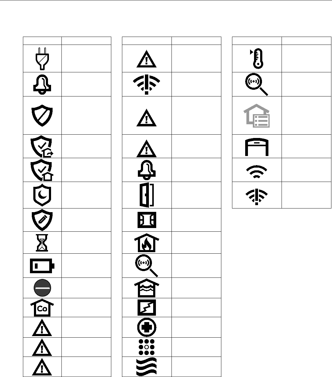
System Displays
The following icons will be displayed on the Home screen along with specific zone status information (if
applicable) to indicate system status.
DISPLAY
DEFINITION
DISPLAY
DEFINITION
DISPLAY
DEFINITION
AC Loss
901 Expansion
Module Tamper
Temperature
Alarm
(Intrusion)
950 Comm.
Trouble
Other
Ready To Arm
988 RF Jam
(5800 Series
Wireless Device)
Automation
Icon
(Z-Wave Node
Failure OR Z-
Wave Controller
Not Ready)
Armed Away
990 RF Jam
(SiX Series
Wireless Device)
Garage Door
Open
Armed Stay
998 Local
Alarm
WiFi source
present and
signal strength
Armed Night
Stay
Door Open
No WiFi source
Armed Custom
Window Open
Restart Timer
Fire
OR
Heat Sensor
Battery Low
Environmental
Bypassed
Zones
Flood
CO Alarm
Glass Break
Reporter
Failure
Medical Alarm
Low Batt
850 Keypad
Keypad
900 Cover
Tamper
Motion
Zone Status Displays
The icons associated with the programmed zones are displayed on the Zones screen. The icon’s color
indicates the zone status (i.e.; yellow icon indicates the zone is faulted and a red icon indicate the zone
is in alarm). In addition a bypass icon is displayed alongside the icon for a bypassed zone.

Lyric Gateway Installation and Reference Guide
- 24 -
System Operation (Continued)
ETL
Audio alarm verification has not been evaluated by ETL.
Audio Alarm Verification (Two-Way Voice Feature)
This feature allows the Central Station operator to listen, talk to or conduct a two-way conversation with an
individual(s) at the premises. It also assists the operator in gathering information about the nature and location
of the alarm that may be helpful in responding to police and fire departments. All Lyric Controllers are capable
of supporting the Two-Way Voice feature. The Lyric Gateway does not make system announcements when the
Two-Way Voice feature is active.
If a WiFi connection is being used for Two-Way Voice (AAV), sufficient bandwidth must be available.
• AAV requires a continuous WiFi upload/download bandwidth of 90kbps for proper operation.
• WiFi bandwidth less than 90kbps may result in degraded performance.
Activation
Fire and CO alarms will prevent the Lyric Gateway from starting an AAV session. A new Fire or
CO alarm will end an AAV session that is in progress.
The controller sends the “alarm message” followed by a “Listen-in-to-Follow message” (Contact ID® code 606)
to the Central Station. The Listen-in-to-Follow message causes the Central Station’s digital receiver to
temporarily hold the phone line for approximately 1 minute. When the controller receives the “kissoff” from the
Central Station, indicating that the alarm message has been received, the Two-Way Voice (AAV) feature is
activated in the (default) “Listen Mode” and sirens and keypad sounds are discontinued. The controller transmits
a beep acknowledgment to the Central Station, once per second. The beep alternates between two tones and
indicates that the controller is waiting for a session command from the Central Station operator. Once a
command is issued the beep acknowledgement is discontinued, however, if a command is not issued within two
minutes the system will “time out” and the call will be terminated.
Operator Commands
The Central Station operator begins the session, which last 5 minutes, by entering one of the valid AAV
commands shown in the table below. The session may be extended 5 minutes, without changing the operating
mode, by pressing the [7] key on the touch-tone phone. Selecting another operating mode also resets the
session an additional 5 minutes. During the last minute of the 5 minute, session, the controller generates two
beeps every 30 seconds to alert the Central Station operator that the session is about to time out. The Central
Station operator may then extend the session by pressing the [7] key on the touch-tone phone. If the session is
not extended, the phone line is disconnected and the session is ended. Sessions may be ended at any time by
pressing the [9] key on the touch-tone phone. The AAV modes are described as follows:
Note: When entering AAV commands make sure the Central Station receiver has been disconnected
from the phone line, otherwise AAV commands may not go through.
Key
Function
1 Talk Mode: Pressing the [1] key on the touch tone phone, enables one-way voice communication
from the Central Sation to the violated premises, and allows the operator to communicate through
the controller’s built-in speaker. In this mode the controller’s Panic and Home buttons blink
alternately.
2 VOX (Voice) Mode: Pressing the [2] key on the touch-tone phone, enables two-way voice
communications between the Central Station and the violated premises via the controller’s built-in
speaker and microphone. In this mode the controller’s Panic button is lit Red and the Home button is
alternately lit Red and Green.
3 Listen Mode: Pressing the [3] key on the touch-tone phone, Enables one-way audio from the violated
premises to the Central Station. The Listen Mode is the start up default mode of the voice feature and
allows the operator to listen through the controller microphone. This mode does not affect
the existing
LED pattern.
7 Extends the session 5 minutes without changing its operating mode.
9 Ends the session and disconnects the phone line.

Lyric Controller Installation and Reference Guide
- 25 -
System Operation
Event Log
The Lyric Gateway Series event log is capable of recording and displaying up to 6,000 system events. These
events are stored locally in the Gateway, in chronological order, and transmitted to the Central Station. When
the maximum number of events is reached in the Event Log, the system will overwrite the oldest event first. The
type of events that can be recorded is selectable and is programmed in the System Type programming field.
The event log can be reviewed by entering the Installer Programming or Master User Programming mode and
selecting “Events”. Refer to the Lyric Gateway User Manual for additional information. The Events and CID
Codes displayed vary according to the options that are programmed. The tables below provide definitions of
the events/codes that may be transmitted to the Central Station and/or displayed by the controller.
Note: In the unlikely condition that the backup battery becomes fully discharged when AC power is lost, any system activity
performed after the low battery notification will not be saved in the event log. Additionally, the controller will revert to
the status condition as before the low battery notification.
Contact ID® Event Log Codes
CID Code
Definition
Event Log Display
110
Alarm, Fire
Fire
121
Alarm, Duress
Duress
122
Alarm, Silent
Silent
123
Alarm, Audible
Audible
131
Alarm, Perimeter
Perimeter
132
Alarm, Interior
Interior
134
Alarm, Entry/Exit
Entry/Exit
135
Alarm, Day/Night
Day Night
137
Alarm, Tamper
Tamper
145
Expansion Module Tamper
Expansion Module Tamper
146
Silent Burglary
Silent Burglary
150
24-Hour Non-Burglary
24 Hour Non-Burglary
162
Carbon Monoxide Detected
Carbon Monoxide Detected
301
Trouble, AC Loss
AC Loss
302
Trouble, Low System Battery
Low system battery
305
Trouble, System Reset
System Reset
308
System shutdown
System shutdown
316
System Tamper*
System Tamper
341
Trouble, Case Tamper
Cover Tamper
344
Trouble, RF Receiver Jam Detect
RF Jam Detect
350
Long Range Radio Reset
Long Range Radio Reset
353
Trouble, Long Range Radio Transmitter Fault
Comm. Trouble
354
Failure to Communicate Event
Failure to Communicate Event
373
Trouble, Fire Trouble
Fire trouble
374
Trouble, Exit Error Alarm
Exit error alarm
380
Trouble, Sensor
Sensor trouble
381
Trouble, Loss of Supervision RF
Superv Loss-RF
383
Trouble, Sensor Tamper
Sensor Tamper
384
RF Low Battery
RF Low Battery
401
Open/Close by User
Arm Away/Disarmed
403
Open/Close Automatic
Automatic O/C (or Scheduled Arming)
406
Cancel
Cancel
407
Remote Arm/Disarm
Remote Arm/Disarm
408
Quick Arm
Quick arm
441
Armed Stay
Arm Stay/Disarmed
455
Auto-Arm Failed
Auto-arm Failed
459
Recent Close
Recent Closing
461
Wrong Code Entry
Wrong Code Entry
570
Zone/Sensor Bypass
Zone Bypass
601
Manual Trigger Test Report
Manual Trigger Test Report
602
Periodic Test Report
Periodic test report
606
Listen-in to follow
Listen-in to follow
607
Walk Test
Walk Test Mode
623
Event 90% Full
Event Log 90% Full
627
Program Mode Entry
Program mode entry
628
Program Mode Exit
Program mode exit
654
System Inactivity
System Inactivity
655
Reset Master Code
User Code
*If APL is enabled, AlarmNet 360TM will generate a special comm. fail message (E316) if it does not hear from a unit within 15 minutes
after a delayed alarm is delivered. This message is meant to alert the Central Station that the system has been tampered with and may
have been compromised.

Lyric Gateway Installation and Reference Guide
- 26 -
System Operation
Contact ID® Event Log Codes
CID Code
Definition
Event Log Display
759
Resident Monitor Zone Response
Resident Monitor Zone Response
760
Resident Response Zone Response
Resident Response Zone Response
761
General Monitor Zone Response
General Monitor Zone Response
762
General Response Zone Response
General Response Zone Response
1401
Local Alarm
Local Alarm
3000
Binary Switch Off
Switch Off (Z-Wave Device)
3001
Binary Switch On
Switch On (Z-Wave Device)
3100
Multi Level Switch Change Level (Off)
Multilevel Switch Off (Z-Wave Device)
3101
Multi Level Switch Change Level (On)
Multilevel Switch On (Z-Wave Device)
3200
Garage Door Close
Garage Door Close
3201
Garage Door Open
Garage Door Open
3300
Door Lock Unlocked
Door Unlocked (Z-Wave Device)
3301
Door Lock Locked
Door Locked (Z-Wave Device)
3302
Door Lock Jammed
Door Lock Jammed (Z-Wave Device)
3400
Thermostat Mode Off
Thermostat Mode Off
3401
Thermostat Mode Heat
Thermostat Mode Heat
3402
Thermostat Mode Cool
Thermostat Mode Cool
3403
Thermostat Mode Auto
Thermostat Mode Auto
3404
Thermostat Mode Aux /Em Heat
Thermostat Mode Aux /Em Heat
3405
Thermostat Fan Mode Auto
Thermostat Fan Mode Auto
3406
Thermostat Fan Mode Manual On
Thermostat Fan Mode Manual On
3407
Thermostat Fan Mode Circulate
Thermostat Fan Mode Circulate
3408
Thermostat Set Heat Point
Thermostat Set Heat Point (and temperature)
3409
Thermostat Set Cool Point
Thermostat Set Cool Point (and temperature)
3410
Thermostat Hold
Thermostat Hold
3411
Thermostat No Scheduling
Thermostat No Scheduling
3412
Thermostat Normal Mode
Thermostat Normal Mode
3500
Low Battery
Low Battery (Z-Wave Device)
3501
Low Battery Restore
Low Battery Restore (Z-Wave Device)
4000
Voice Command Success
Displays Variable Voice Command Text
4001
Voice Command Failed
Displays Variable Voice Command Text
4002
Voice Trigger Success
Displays Variable Voice Trigger Text
4003
Voice Trigger Fail
Displays Variable Voice Trigger Text
5000
Critical Panel Firmware Update Downloaded
Critical Panel Update Downloaded
Central Station Messages
The following messages are sent by the controller internal cellular or WiFi devices for the conditions listed
below.
Alarm Condition
Alarm Code
Restore Code
Power On / Reset
E33900950
Primary Communication Path Supervision
E350C0951
R350C0951
Secondary Communication Path Supervision
E350C0952
R350C0952
Test
555555559
Lyric Controller Installation and Reference Guide
- 27 -
Testing the System
TO THE INSTALLER
Regular maintenance and inspection (at least annually) by the installer and frequent testing by the user are
vital to continuous satisfactory operation of any alarm system.
The installer should assume the responsibility of developing and offering a regular maintenance program to
the user as well as acquainting the user with the proper operation and limitations of the alarm system and its
component parts. Recommendations must be included for a specific program of frequent testing (at least
weekly) to ensure the system’s proper operation at all times.
Test Modes
The following tests are available to the Installer or User via the “Advanced” programming option:
Option
Function
System
Information
System Information is displayed. Select OK to return to the previous screen.
Walk Test The Walk Test mode allows each protection point to be checked for proper operation.
Refer to the User Manual for additional information.
Comm. Test
The following tests are available to the Installer via the Gateway keypad.
RF Sniffer Test
Used to verify the RF transmitters have been properly installed.
Go-No-Go Test
Used to verify adequate RF signal strength from proposed transmitter locations.
Diagnostics
Provides access to the Reboot Feature. Refer to the paragraph in this section for additional
information regarding this feature.
Zone Discovery
Provides access to the Zone Discovery mode. Refer to the paragraph in this section for
additional information regarding the Zone Discovery feature.
Testing the System
After installation is completed, the security system should be carefully tested, as follows:
Step
Action
1. With the system in the disarmed state, check that all zones are intact. If the Status Shield is not lit
green, select the “Security” icon on the Smart Device
followed by the “Zones” icon to display the
faulted zone(s). If necessary, restore faulted zone(s) so that the “Home” button lights. Fault and
restore every sensor individually to assure that it is being monitored by the system.
Armed System Test (via AlarmNet 360)
Alarm messages will be sent to the Central Station during the following steps 1 and 2. Notify the Central Station
in advance that tests will be in progress.
Step
Action
1. Arm the system and fault one or more zones. Silence alarm sounder(s) and disarm the system by
selecting “Disarmed” and entering the Security Code. Check entry/exit delay zones.
2. Check the keypad-initiated alarms that are in the system by selecting “Emergency” followed by
applicable Panic keys. If the system has been programmed for audible emergency, the keypad will
emit a steady alarm sound, and “Alert” will flash red. In addition, “ALARM” and zone number will be
displayed on Smart Device. Silence the alarm by selecting “Disarmed” and entering the Security
Code. If the system has been programmed for silent emergency, there will be no audible alarms or
displays, but a report will be sent to the Central Station.
3. Notify the Central Station when all tests are finished, and verify results with them.
4. To test the wireless part of the system and the RF receiver, perform the RF Sniffer Mode and Go-No-
Go Tests.
NOTE: System Test mode and Go/No Go Test will be automatically terminated after 3-1/2 to 4 hours if the
installer or user does not manually terminate it. This ensures that fire and panic zones will not remain
disabled. However, Sniffer mode does not automatically expire. You must manually exit Sniffer mode by
selecting the Home key and entering the Master Code, to return to normal operation. During the final 5
minutes the system will emit double beeps indicating that the end of Test mode is nearing.
Lyric Gateway Installation and Reference Guide
- 28 -
Testing the System
(Continued)
RF Sniffer Test Mode
This mode is used to verify that all transmitters have been properly programmed. Sniffer Mode does not
automatically expire. You must manually exit Sniffer Mode to return to normal operation.
Go-No-Go Test Mode
Conducting this test with your hand wrapped around the transmitter will cause inaccurate results.
If a button is pressed on a transmitter that has been programmed to set ARM AWAY, ARM STAY,
or DISARM, the system will exit the Go/No Go Test mode and the programmed action will occur.
The Go-No-Go tests is used to verify adequate RF signal strength from the proposed transmitter location, and
allow you to reorient or relocate transmitters if necessary, before mounting the transmitters permanently. This
mode is similar to the RF Sniffer Mode, except that the wireless receiver gain is reduced. This will enable you to
make sure that the RF signal from each transmitter is received with sufficient signal amplitude when the system
is in the normal operating mode. During Go/No-Go mode the system beeps every 30-40 seconds.
Enter Go/No-Go Test mode
1. Enter Installer Code (4112) + 11 + 51 (on the Gateway keypad).
Exit Go/No-Go Test mode
1. Select “Disarmed”+ Enter Installer Code (4112).
Zone Discovery Mode
Zone Discovery mode requires Installer supervision when in use. The system is not fully operational
for fire or life safety while Zone Discovery Mode is active.
Zone discovery mode can be used to remotely view all zones that have been programmed in the system for
operation. The zones must have a response type programmed and in the case of RF zones, must also have a
serial number programmed. All zones programmed (except for duress) will be displayed.
Enter Zone Discovery
1. With the System in the Installer Programming mode, select the “Test” button and then select the “Zone
Discovery” button. The “Zone Discovery” button will be highlighted indicating that the mode is active.
Exit Zone Discovery
1. Select the Home key and enter the Master Code. If you do not exit Zone Discovery mode manually, the
system will automatically exit zone discovery mode in approximately 1-4 minutes dependent upon the
number of zones that are programmed. The system beeps once and returns to the home screen.
Rebooting the System
The Reboot function allows you to restart the system if required. To reboot the system perform the following:
Step
Action
1. Select the “Security” icon followed by the “Tools” icon.
2. Enter the Master User code (1234) and select the “Advanced” icon.
3. Select the “Reboot” button. A confirmation screen appears.
4. Select “Yes” to reboot the Gateway.
NOTE: After the reboot sequence is complete it is recommended that you perform a “Walk Test” to verify that
all transmitters are operational in the system.

Lyric Controller Installation and Reference Guide
- 29 -
Programming Default Values
Programming Field
Options
Programmed
Default
System
Alarm Report Delay
No delay, 15 Seconds, 30 Seconds, 45 Seconds
30 Seconds
Burglary Alarm Sound
Yes, No
Yes
Daylight Savings Time
Yes, No
Yes
Time Zone Offset
(UTC-5:00 Eastern
Time (US & Canada)
Software Version
XX.XX.XXXXX.XXX
XX.XX.XXXXX.XXX
Temperature Unit
Fahrenheit, Celsius
Fahrenheit
Installer Language
English, Spanish, French, Portuguese
English
Two-way Voice
Not programmable
No
Local Programming Lockout
Yes, No
No
Z-Wave Support
Yes, No
Yes
Display alarm Cancel
Yes, No
Yes
Lack of Usage Notify
Disabled, 1 Day, 7 Days, 27 Days, 90 Days, 180
Days, 365 Days
Disabled
RF Jam
Disabled, RF Jam Log, RF Jam Log and Report
RF Jam Log
Number of Reports (Swinger Shutdown)
1, 2, 3, 4, 5, 6
2
First Test Report Offset
6 Hours, 12 Hours, 18 Hours, 24 Hours
6 Hours
Report Frequency
Never, Every Day, Every 7 Days, Every 30 Days
Never
System
Not programmable
Yes
Reporter
Not programmable
Yes
Panel Sync Delay Time
0 Minutes - 120 Minutes
3 Minutes
Z-Wave Door Lock
Disabled, Arm Stay, Arm Away, Arm Without
Autostay
Disabled
Area
Area Number
1
1
Entry Delay 1
None, 15 Seconds, 30 Seconds, 45 Seconds, 60
Seconds, 90 Seconds, 2 Minutes, 3 Minutes, 4
Minutes
30 Seconds
Entry Delay 2
None, 15 Seconds, 30 Seconds, 45 Seconds, 60
Seconds, 90 Seconds, 2 Minutes, 3 Minutes, 4
Minutes
30 Seconds
Exit Delay
45 Seconds,60 Seconds, 90 Seconds, 120
Seconds
60 Seconds
Burglary Bell Timeout
No, 4 Minutes, 8 Minutes,12 12 Minutes, 16
Minutes,
4 Minutes
Fire Bell Timeout
No, 4 Minutes, 8 Minutes,12 12 Minutes, 16
Minutes,
4 Minutes
Quick Arm
Yes, No
Yes
Quick Exit
Yes, No
Yes
Restart Exit Time
Yes, No
Yes
Chime Mode
Yes, No
Yes
Force Bypass
Yes, No
No
Exit Warning
Not programmable
Yes
Display Exit Time
Yes, No
Yes
Power-Up In Previous
Not programmable
Yes
Auto Stay Arming
Yes, No
Yes
Arm Confirm
All RF, None, RF Keyfob, RF Keypad
None
Communicator
City ID
01-99
Blank
CS ID
01-FE
Blank
Sub ID
0001-9999
Blank
Supervision
None, 24 Hours, 30 Days
30 days
High Usage Plan
Yes, No
No
Old Alarm Time
10 Minutes, 15 Minutes, 30 Minutes, 1 Hour, 2
Hours, 4 Hours, 8, Hours, 12 Hours, 24 Hours
10 Minutes
IP Fault Time
1 – 99 Minutes
60 Minutes
Communications Path (Inter. Dev.)
Cellular, WiFi - IP
WiFi - IP

Lyric Gateway Installation and Reference Guide
- 30 -
Programming Default Values
Programming Field
Options
Programmed
Default
Use DHCP
Yes, No
Yes
NIC IP Address
Up to 12 digits
255.255.255.255
Subnet Mask
Up to 12 digits
255.255.255.255
Gateway IP Address
Up to 12 digits
255.255.255.255
DNS Server IP Address
Up to 12 digits
255.255.255.255
Cellular Fault Time
1 – 99 Minutes
60 Minutes
Cellular 24 Hr Test/UL864 Comm. Fire
Yes, No
No
Cellular Rollover
Yes, No
Yes
Reporter
Arm Away
Yes, No
Yes
Arm Stay
Yes, No
Yes
Disarm
Yes, No
Yes
Exit Error
Not programmable
Yes
Alarm Restore
Yes, No
Yes
Alarm Cancel
Yes, No
Yes
Test
Not programmable
Yes
Test Restore
Not programmable
Yes
Low Battery
Yes, No
Yes
Low Battery Restore
Yes, No
Yes
RF Low Battery
Yes, No
Yes
RF Low Battery Restore
Yes, No
Yes
Recent Closing
Not programmable
Yes
Event Log Full
Yes, No
No
Trouble
Yes, No
Yes
Trouble Restore
Yes, No
Yes
Bypass
Yes, No
Yes
Bypass Restore
Yes, No
Yes
AC Loss
Yes, No
Yes
AC Loss Restore
Yes, No
Yes
Log All Events
Yes, No
Yes
Log Alarm Events
Yes, No
Yes
Log Open/Close Events
Yes, No
Yes
Log Trouble Events
Yes, No
Yes
Log Non Security Events
Yes, No
Yes
Log Bypass Events
Yes, No
Yes
Zone Programming
The defaults are shown. Refer to the Programming Field Explanations for additional information.
Zones 1-64 are RF Zones, RF Zones 65-69 are Garage Door Zones. (Refer to “SENSORS” in AlarmNet 360)
Zones 131-162 are Keyfob Zones (Refer to “KEYFOBS” in AlarmNet 360)
Zones 280-291 are Temperature Zones (Refer to “SENSORS” in AlarmNet 360)
Zones 850-857 are Keypad Zones (Refer to “KEYPADS” in AlarmNet 360)
Zones 995, 996, 998 and 999 are Panic Zones (Refer to “SENSORS” in AlarmNet 360)

Lyric Controller Installation and Reference Guide
- 31 -
Programming Default Values (Continued)
For Zone Programming Options refer to Explanation of Zone Assignment Table Headings
Zone
No.
Loop
No.
Device
Type
Response Type
Alarm
Report
Chime
Supervision
Arm
Night
Zone
Descriptor
1
2
Door
Entry Exit 1
Yes
Standard
Supervised
N/A
Front
2
2
Door
Entry Exit 1
Yes
Standard
Supervised
N/A
Back
3
2
Window
Perimeter
Yes
Standard
Supervised
N/A
4
2
Window
Perimeter
Yes
Standard
Supervised
N/A
5
2
Window
Perimeter
Yes
Standard
Supervised
N/A
6
2
Window
Perimeter
Yes
Standard
Supervised
N/A
7
1
Motion Sensor
Interior with Delay
Yes
Disabled
Supervised
No
8
8
Smoke Detector
Fire No Verification
Yes
Disabled
Supervised
N/A
9-64
See Programming Field Explanations
131
3
Key Fob
Arm Away
Yes
Disabled
Button
N/A
132
2
Key Fob
Disarm
Yes
Disabled
Button
N/A
133
4
Key Fob
No Response
No
Disabled
Button
N/A
134
1
Key Fob
No Response
No
Disabled
Button
N/A
135
3
Key Fob
Arm Away
Yes
Disabled
Button
N/A
136
2
Key Fob
Disarm
Yes
Disabled
Button
N/A
137
4
Key Fob
No Response
No
Disabled
Button
N/A
138
1
Key Fob
No Response
No
Disabled
Button
N/A
139
3
Key Fob
Arm Away
Yes
Disabled
Button
N/A
140
2
Key Fob
Disarm
Yes
Disabled
Button
N/A
141
4
Key Fob
No Response
No
Disabled
Button
N/A
142
1
Key Fob
No Response
No
Disabled
Button
N/A
143
3
Key Fob
Arm Away
Yes
Disabled
Button
N/A
144
2
Key Fob
Disarm
Yes
Disabled
Button
N/A
145
4
Key Fob
No Response
No
Disabled
Button
N/A
146
1
Key Fob
No Response
No
Disabled
Button
N/A
147
3
Key Fob
Arm Away
Yes
Disabled
Button
N/A
148
2
Key Fob
Disarm
Yes
Disabled
Button
N/A
149
4
Key Fob
No Response
No
Disabled
Button
N/A
150
1
Key Fob
No Response
No
Disabled
Button
N/A
151
3
Key Fob
Arm Away
Yes
Disabled
Button
N/A
152
2
Key Fob
Disarm
Yes
Disabled
Button
N/A
153
4
Key Fob
No Response
No
Disabled
Button
N/A
154
1
Key Fob
No Response
No
Disabled
Button
N/A
155
3
Key Fob
Arm Away
Yes
Disabled
Button
N/A
156
2
Key Fob
Disarm
Yes
Disabled
Button
N/A
157
4
Key Fob
No Response
No
Disabled
Button
N/A
158
1
Key Fob
No Response
No
Disabled
Button
N/A
159
3
Key Fob
Arm Away
Yes
Disabled
Button
N/A
160
2
Key Fob
Disarm
Yes
Disabled
Button
N/A
161
4
Key Fob
No Response
No
Disabled
Button
N/A
163
1
Key Fob
No Response
No
Disabled
Button
N/A
280
N/A
Temperature
Monitor
Yes
Disabled
High Temp
N/A
281
N/A
Temperature
Monitor
Yes
Disabled
Low Temp
N/A
282
N/A
Temperature
Monitor
Yes
Disabled
High Temp
N/A
283
N/A
Temperature
Monitor
Yes
Disabled
Low Temp
N/A
284
N/A
Temperature
Monitor
Yes
Disabled
High Temp
N/A
285
N/A
Temperature
Monitor
Yes
Disabled
Low Temp
N/A
286
N/A
Temperature
Monitor
Yes
Disabled
High Temp
N/A
287
N/A
Temperature
Monitor
Yes
Disabled
Low Temp
N/A
288
N/A
Temperature
Monitor
Yes
Disabled
High Temp
N/A
289
N/A
Temperature
Monitor
Yes
Disabled
Low Temp
N/A
290
N/A
Temperature
Monitor
Yes
Disabled
High Temp
N/A
291
N/A
Temperature
Monitor
Yes
Disabled
Low Temp
N/A
850
N/A
SiX™ Keypad
N/A
N/A
N/A
60Min
N/A
851
N/A
SiX™ Keypad
N/A
N/A
N/A
60Min
N/A
852
N/A
SiX™ Keypad
N/A
N/A
N/A
60Min
N/A
853
N/A
SiX™ Keypad
N/A
N/A
N/A
60Min
N/A
854
N/A
SiX™ Keypad
N/A
N/A
N/A
60Min
N/A
855
N/A
SiX™ Keypad
N/A
N/A
N/A
60Min
N/A
856
N/A
SiX™ Keypad
N/A
N/A
N/A
60Min
N/A
857
N/A
SiX™ Keypad
N/A
N/A
N/A
60Min
N/A
995
N/A
Fire
Fire No Verification
Yes
Disabled
Panic Trigger
N/A
996
N/A
Medical
24 Hour Auxiliary
Yes
Disabled
Panic Trigger
N/A
998
N/A
Local Alarm
Local Alarm
Yes
Disabled
Panic Trigger
N/A
999
N/A
Police
24 Hour Silent
Yes
Disabled
Panic Trigger
N/A
Lyric Gateway Installation and Reference Guide
- 32 -
Programming Default Values (Continued)
Explanation of Zone Assignment Table Headings
Loop Number - Used with 5800 Devices. Entries are 1-4, depending on device being used. Refer to the
transmitter’s instructions or the figure provided for appropriate loop numbers.
Device Type- Dependent upon the Zone Number being programmed.
Response Type - Dependent upon the Device Type that has been selected.
Alarm Report – Activate/Deactivate reporting option for the device.
Options: Yes, No
Chime – Enable/Disable chime sounding for the device (applies to Entry/Exit, Perimeter and Interior Response
Types only).
Disabled
Melody Long
Alert 1
Doorbell 2
Standard
Ascend
Alert 2
Evolve
Melody
Ascend Long
Doorbell 1
Supervision - Dependent upon the Zone Number being programmed.
Wireless Zone
(Zone 1-69)
Key Zone
(Zone 131-162)
Temperature Zone
(Zone 280-291)
Supervised
Button
High Temp
Unsupervised
Low Temp
Arm Night – Activate/Deactivate specific Motion Sensors at (applies to Motion Sensor Response Type only).
Options: Yes, No
Zone Description1/2 – Enter Zone Descriptors on displayed keypad. System Announces pre-programmed voice
descriptors.
Device/Response Type Matrix
Device Type
Response Type
Entry Exit 1
Entry Exit 2
Perimeter
Resident Monitor
Resident Response
General Monitor
General Response
Day/Night
Interior Follower
Interior With Delay
Fire No Verification
Fire With Verification
Carbon Monoxide
24 Hour Auxiliary
24 Hour Audible
24 Hour Silent
Monitor
Not Used
Arm Stay
Arm Away
Disarm
No Response
Silent Burglary
Garage
Garage Monitor
Trouble
Local Alarm
Carbon Monoxide Detector
x
Door
x
x
x
x
x
x
x
Environmental
x
x
Fire
x
x
Flood
x
x
Garage Door
x x
Glass Break
x x x x x
Heat Sensor
x
Medical
x x
x
Motion Sensor
x x x x x x x x
Other
x x x x x x x x x x x x x x x x x x x x x x x x x x x
Police
x
x
x
x
Smoke Detector
x
x
Temperature
x
x
Window
x x x x x x x

Lyric Controller Installation and Reference Guide
- 33 -
Zone Response Type Matrix
SiX™ Series Device Signal Strength
Signal strength for the enrolled SiX Series Devices is displayed on the Zone Programming Screen for the
individual Zone that is programmed. Signal strength information is provided below.
Icon
Description
Signal Strength
Four Green Bars
Supérieure à -27 dBm
Three Green Bars
Supérieure à -45 dBm
Two Green Bars
Supérieure à -63 dBm
One Green Bar
Supérieure à -81 dBm
Four Red Bars
Inférieure à -81 dBm (en dessous du seuil)
Lyric Gateway Installation and Reference Guide
- 34 -
Regulatory Agency Statements
Federal Communications Commission (FCC) Part 15
The user shall not make any changes or modifications to the equipment unless authorized by the Installation Instructions or User's
Manual. Unauthorized changes or modifications could void the user's authority to operate the equipment.
CLASS B DIGITAL DEVICE STATEMENT
NOTE: This equipment has been tested and found to comply with the limits for a Class B digital device, pursuant to part 15 of the FCC
Rules. These limits are designed to provide reasonable protection against harmful interference in a residential installation. This
equipment generates, uses and can radiate radio frequency energy and, if not installed and used in accordance with the instructions,
may cause harmful interference to radio communications. However, there is no guarantee that interference will not occur in a
particular installation. If this equipment does cause harmful interference to radio or television reception, which can be determined by
turning the equipment off and on, the user is encouraged to try to correct the interference by one or more of the following measures:
• Reorient or relocate the receiving antenna.
• Increase the separation between the equipment and receiver.
• Connect the equipment into an outlet on a circuit different from that to which the receiver is connected.
• Consult the dealer or an experienced radio/TV technician for help.
This Class B digital apparatus complies with Canadian ICES-003.
Cet appareil numérique de la classe B est conforme à la norme NMB-003 du Canada.
FCC IC Statement
This device complies with Part 15 of FCC Rules and RSS-210 of Industry Canada. Operation is subject to the following two conditions:
(1) This device may not cause harmful interference, and (2) This device must accept any interference received, including interference
that may cause undesired operation.
Cet appareil est conforme à la partie 15 des règles de la FCC & de RSS-210 des Industries Canada. Son fonctionnement est soumis aux
conditions suivantes: (1) Cet appareil ne doit pas causer d' interferences nuisibles. (2) Cet appareil doit accepter toute interference
reçue y compris les interferences causant une reception indésirable.
RF Exposure Warning
The antenna(s) used for this transmitter must be installed to provide a separation distance of at least 7.8 in (20 cm)
from all persons and must not be co-located or operated in conjunction with any other transmitter except in
accordance with FCC multi-transmitter product procedures.
Mise en Garde
Exposition aux Frequences Radio:
L'antenne (s) utilisée pour cet émetteur doit être installée à une distance de
séparation d'au moins 7,8 pouces (20 cm) de toutes les personnes.
IMPORTANT NOTES ABOUT EXTERNAL ANTENNAS
If an external cellular radio antenna is used, the antenna may be installed or replaced ONLY by a professional
installer.
TO THE INSTALLER
For the Lyric-3G, the external antenna must not exceed a maximum directional gain (including cable loss) of 3.2
dBi at 850 MHz and 2.3 dBi at 1900 MHz.
For the Lyric-CDMA, the external antenna must not exceed a maximum directional gain (including cable loss) of
8.5 dBi at 850 MHz and 4.1 dBi at 1900 MHz.

Lyric Controller Installation and Reference Guide
- 35 -
WARNING
THE LIMITATIONS OF THIS ALARM SYSTEM
While this System is an advanced design security system, it does not offer guaranteed protection against burglary, fire
or other emergency. Any alarm system, whether commercial or residential, is subject to compromise or failure to warn
for a variety of reasons. For example:
• Intruders may gain access through unprotected openings or have the technical sophistication to bypass an alarm
sensor or disconnect an alarm warning device.
• Intrusion detectors (e.g., passive infrared detectors), smoke detectors, and many other sensing devices will not
work without power. Battery-operated devices will not work without batteries, with dead batteries, or if the
batteries are not put in properly. Devices powered solely by AC will not work if their AC power supply is cut off for
any reason, however briefly.
• Signals sent by wireless transmitters may be blocked or reflected by metal before they reach the alarm receiver.
Even if the signal path has been recently checked during a weekly test, blockage can occur if a metal object is
moved into the path.
• A user may not be able to reach a panic or emergency button quickly enough.
• While smoke detectors have played a key role in reducing residential fire deaths in the United States, they may not
activate or provide early warning for a variety of reasons in as many as 35% of all fires, according to data
published by the Federal Emergency Management Agency. Some of the reasons smoke detectors used in
conjunction with this System may not work are as follows. Smoke detectors may have been improperly installed
and positioned. Smoke detectors may not sense fires that start where smoke cannot reach the detectors, such as
in chimneys, in walls, or roofs, or on the other side of closed doors. Smoke detectors also may not sense a fire on
another level of a residence or building. A second floor detector, for example, may not sense a first floor or
basement fire. Finally, smoke detectors have sensing limitations. No smoke detector can sense every kind of fire
every time. In general, detectors may not always warn about fires caused by carelessness and safety hazards like
smoking in bed, violent explosions, escaping gas, improper storage of flammable materials, overloaded electrical
circuits, children playing with matches, or arson. Depending on the nature of the fire and/or location of the smoke
detectors, the detector, even if it operates as anticipated, may not provide sufficient warning to allow all
occupants to escape in time to prevent injury or death.
• Passive Infrared Motion Detectors can only detect intrusion within the designed ranges as diagrammed in their
installation manual. Passive Infrared Detectors do not provide volumetric area protection. They do create multiple
beams of protection, and intrusion can only be detected in unobstructed areas covered by those beams. They
cannot detect motion or intrusion that takes place behind walls, ceilings, floors, closed doors, glass partitions, glass
doors, or windows. Mechanical tampering, masking, painting or spraying of any material on the mirrors, windows
or any part of the optical system can reduce their detection ability. Passive Infrared Detectors sense changes in
temperature; however, as the ambient temperature of the protected area approaches the temperature range of
90° to 105°F (32° to 40°C), the detection performance can decrease.
• Alarm warning devices such as sirens, bells or horns may not alert people or wake up sleepers if they are located
on the other side of closed or partly open doors. If warning devices are located on a different level of the
residence from the bedrooms, then they are less likely to waken or alert people inside the bedrooms. Even persons
who are awake may not hear the warning if the alarm is muffled by noise from a stereo, radio, air conditioner or
other appliance, or by passing traffic. Finally, alarm warning devices, however loud, may not warn hearing-
impaired people.
• Communication paths needed to transmit alarm signals from a premises to a central monitoring station may be out
of service or temporarily out of service. Communication paths are also subject to compromise by sophisticated
intruders.
• Even if the system responds to the emergency as intended, occupants may have insufficient time to protect
themselves from the emergency situation. In the case of a monitored alarm system, authorities may not respond
appropriately.
• This equipment, like other electrical devices, is subject to component failure. Even though this equipment is
designed to last as long as 10 years, the electronic components could fail at any time.
The most common cause of an alarm system not functioning when an intrusion or fire occurs is inadequate
maintenance. This alarm system should be tested weekly to make sure all sensors and transmitters are working
properly. The security keypad (and remote keypad) should be tested as well.
Wireless transmitters are designed to provide long battery life under normal operating conditions. Longevity of
batteries may be as much as 4 to 7 years, depending on the environment, usage, and the specific wireless device being
used. External factors such as humidity, high or low temperatures, as well as large swings in temperature, may all
reduce the actual battery life in a given installation. This wireless system, however, can identify a true low battery
situation, thus allowing time to arrange a change of battery to maintain protection for that given point within the
system.
Installing an alarm system may make the owner eligible for a lower insurance rate, but an alarm system is not a
substitute for insurance. Homeowners, property owners and renters should continue to act prudently in protecting
themselves and continue to insure their lives and property.
We continue to develop new and improved protection devices. Users of alarm systems owe it to themselves and their
loved ones to learn about these developments.

Lyric Gateway Installation and Reference Guide
- 36 -
Agency Notices
1. For Residential Burglar Alarm installations with line security, total exit delay time must not exceed 60
seconds. For Burglar Alarm installations without line security, total exit delay time must not exceed 120
seconds.
2. Periodic testing must be at least every 24 hours.
3. Remote downloading without an alarm company technician on-site (unattended downloading) is not
permissible for ETL installations.
4. As SIA limits for delay of alarm reporting and sounding can exceed UL Standard limits for commercial and
residential applications, the following requirements per UL681 are provided:
The maximum time that a control unit shall be programmed to delay the transmission of a signal to a
remote monitoring location, or to delay the energizing of a local alarm sounding device to permit the
alarm system user to enter and disarm the system, or to arm the system and exit shall not exceed:
a) 60 seconds for a system with standard line security or encrypted line security,
b) 120 seconds for a system without standard line security or encrypted line security, or
c) 120 seconds for a system that does not transmit an alarm signal to a remote monitoring location.
SIA Quick Reference Guide
Programming Section
Feature
Range
Shipping Default
SIA Requirement
Installation and Setup Guide or Programming Guide
Reporter
/
Report Selection
Exit Error Not selectable Enabled Enabled
Recent Closing Not selectable Enabled Enabled
Alarm Cancel Enabled or Disabled Enabled Enabled
Reporter
/Options Number of
Reports
1 to 6 Reports 2 Reports 2 Reports
Alarm Report
Delay (Abort
Window)
15, 30 and 45 seconds
30 seconds
30 seconds*
System Settings
Entry Delay # 1
None, 15, 30, 45, 60 and
90 seconds and 2, 3 or
30 seconds
30 seconds minimum
Entry Delay # 2 None, 15, 30, 45, 60 and
90 seconds and 2, 3 or
30 seconds 30 seconds minimum
Exit Delay
45, 60, 90 seconds and
2 minutes
60 Seconds
45 seconds minimum
Restart Exit Time Enabled or Disabled Yes (Enabled) Enabled
Exit Warning
Not selectable
Yes (Enabled)
Enabled
Auto Stay
Arming
Enabled or Disabled Yes (Enabled) Enabled
Cross Zone Delay
30 seconds and 2
minutes (in 30 second
increments), 3 minutes
None (Disabled)
Enabled and two zones
programmed
Zones
Fire Alarms
Zone Type “Fire with
Verification” must be
selected for Fire Zone
Disabled
Disabled
User Guide
User Functions/
User Access
Duress Duress Code is
Programmed by Master
User as User 48
Disabled Disabled
System Functions/
Testing the System**
System Test System tests provided
as a User Function
n/a n/a
Communications
While the system is in
Test mode, no alarm
reports are sent to the
Central Station
Disabled
Disabled
* Combined Entry Delay and Alarm Report Delay (Abort Window) should not exceed 1 minute.
** Refer to the User Guide for procedures on Testing the System.

Lyric Controller Installation and Reference Guide
- 37 -
Specifications
Lyric Gateway Residential Burglar and Fire Alarm Control Panel
Physical:
Dimensions: 8.75” (222mm) W x 7” (178mm) H x 1.5” (38mm) D
Electrical:
Voltage Input: 110VAC, 60 Hz/9 Vdc from plug-in 2.5A power supply
Rechargeable Backup Battery: Nickel-metal hydride battery pack rated at 7.2 Vdc
Communication:
Formats Supported: ADEMCO Contact ID® Reporting, 10 characters/sec
SIA/DCS Format, 2225Hz Handshake, Data Tones, 2025/2235Hz, baud
For patent information, see www.honeywell.com/patents

Lyric Gateway Installation and Reference Guide
- 38 -
Glossary
AES – Advanced Encryption Standard
APL – Advanced Protection Logic
dBM – decibels milliwatt (power ratio)
CDMA - Code Division Multiple Access is a channel access method used by various radio communication
technologies that allows many users to occupy the same time and frequency allocations in a given band/space.
DHCP – Dynamic Host Configuration Protocol, which provides a mechanism for allocating IP addresses
dynamically so that addresses can be reused when hosts no longer need them.
DNS – Domain Name System, which is a distributed hierarchical naming system used to resolve domain names
(e.g., www.yahoo.com) into numerical IP addresses (e.g., 204.17.25.1).
Ec/Io – Signal to noise ratio of the current channel for CDMA (Measured in dB).
Eb/No – Signal to noise ratio of the current channel for UTMS (3G) (Measured in dB).
ESN – Electronic Serial Number (32 bit number that identifies a CDMA device)
Gateway IP Address – A gateway (sometimes called a router) is a computer and/or software used to connect
two or more networks (including incompatible networks) and translates information from one network to the
other. The Gateway IP address is the IP address for the gateway.
GPRS – General Packet Radio Service
GSM – Global System for Mobile communications, which is an international standard for digital mobile phone
systems used for cellular communication.
HSDPA – High-Speed Downlink Packet Access
HSPA – High-Speed Packet Access
ICCID – Integrated Circuit Card Identifier (SIM Card serial number)
IMEI – International Mobile Equipment Identity number
IP – Internet Protocol
IP Address – A unique number consisting of four parts separated by periods, sometimes called a "dotted quad.,"
for example: 204.17.29.11, assigned to every computer/workstation connected to the Internet. IP numbers can
be "static" (assigned and unchanging) or "dynamic," assigned via DHCP at each and every startup.
ISP – Internet Service Provider
KBPS – Kilobits per second
MAC ID – Media Access Code; located on the module label.
MEID – Mobile Equipment Identifier (56 bit number that identifies a CDMA device)
NIC – Network Interface Card
RSCP – Received Signal Code Power (Ratio of RSSI and Ec/No)
RSSI – Received Signal Strength Indication
SCID – SIM Card ID
Subnet Mask – A Subnet is a portion of a network that shares a network address with other portions of the
network, and is distinguished by a subnet number. The Subnet Mask is a 32-bit address mask used in IP to
indicate the bits of an IP address that are being used for the subnet address.
UMTS – Universal Mobile Telecommunications Service
WEP – Wired Equivalent Privacy
WPA – WiFi Protected Access
WPS – WiFi Protected Setup

Lyric Controller Installation and Reference Guide
- 39 -
Contacting Technical Support
PLEASE, before you call Technical Support, be sure you:
• READ THE INSTRUCTIONS!
• Check all wiring connections.
• Determine that the power supply and/or backup battery are supplying proper voltages.
• Verify your programming information where applicable.
• Note the proper model number of this product, and the version level (if known) along with any
documentation that came with the product.
• Note your Honeywell customer number and/or company name.
Having this information handy will make it easier for us to serve you quickly and effectively.
Technical Support: ...................................................................................................... 1-800-645-7492 (8 a.m.-10 p.m. E.S.T.)
MyWebTech: ................................................................................................................... https://www.mywebtech/honeywell.com

Lyric Gateway Installation and Reference Guide
- 40 -
– Index –
24-Hour Silent ............................................................ 22
300-03864-AIO ........................................................... 7
300-03866-AIO ........................................................... 7
300-04063V1 .............................................................. 10
300-04705V1 .............................................................. 10
5800 Series Transmitter Loop Numbers .......... 14
5800 Series Transmitters ....................................... 13
5802MN ......................................................................... 13
5804E ............................................................................ 13
5816 ................................................................................. 13
5834-4 ........................................................................... 13
5878 ................................................................................ 13
AC Power ...................................................................... 10
AC Power Loss ............................................................. 7
ADEMCO Contact ID ............................................... 39
Armed System Test ................................................. 28
Audio Alarm Verification (Two-Way Voice
Feature) ................................................................... 25
Babysitter Code ........................................................ 22
Backup Battery .................................................. 10, 39
Button Transmitters ................................................. 13
CDMA Cellular Communications Module .......... 11
Communication Modules ......................................... 11
Contact ID Event Log Codes ........................ 26, 27
Contact ID Reporting .............................................. 39
Contacting Technical Support ............................. 41
Devices ............................................................................ 2
Duress Code ............................................................... 22
Enter Installer Programming Mode .................... 18
Enter/Change The Master Code ......................... 22
Entry Delay ................................................................. 20
Entry/Exit Burglary .................................................. 20
Exit Delay ..................................................... 20, 28, 38
Exit Programming Mode ......................................... 19
GSM Cellular Communications Module .............. 11
Home Screen ............................................................... 16
House ID Code ............................................................ 13
House Identification ................................................. 13
Installer Code ............................................................. 22
Installer Tools Menu Screen ................................... 18
Installing Wireless Zones ........................................ 14
Key/Touchscreen Operation ................................ 22
Liquid Crystal Display (LCD) Touch-Screen ... 15
Loading Factory Defaults ....................................... 19
LYRIC-3G ....................................................................... 11
LYRIC-CDMA ................................................................ 11
Master Code ............................................................... 22
Master Security Code.............................................. 22
User Security Code .................................................. 22
Master User Tools Screen ....................................... 17
Memory of Alarm ...................................................... 22
Navigating Menus ................................................ 15, 17
Navigation Keys ......................................................... 16
News ............................................................................... 16
Operator Commands............................................... 25
Panic Key/Icons ........................................................ 22
Plug-In Power Supply ............................................. 10
Range ............................................................................. 13
Reboot .......................................................................... 29
Rebooting the System ............................................ 29
Regulatory Agency Statements .......................... 36
Reset Master User Code ......................................... 23
RF House Code ........................................................... 13
Secondary User Codes ........................................... 22
Security Codes ........................................................... 22
Security Screen .......................................................... 17
Programming Default Tables ................. 30, 31, 32
Sixfob ............................................................................. 13
Six™ Series Transmitters ......................................... 13
Sniffer Mode ............................................................... 28
Specifications ............................................................. 39
Super High Capacity Battery ................................. 11
Supervised RF ............................................................. 13
System Features .................................................... 5, 6
System Operation ..................................................... 22
System Standby Screen .......................................... 18
Technical Support ..................................................... 41
Test Modes .................................................................. 28
Testing the System ........................................... 28, 29
Touch-Screen Display .............................................. 15
Traffic ............................................................................. 16
Transmitter Battery Life .......................................... 13
Transmitter Input Type ............................................ 13
Transmitter Loop Numbers ................................... 14
Transmitter Supervision .......................................... 13
Unsupervised Button ................................................ 13
Unsupervised RF ........................................................ 13
Wall Mounting ........................................................ 8, 10
Wireless Keys .............................................................. 13
Wireless Zones ........................................................... 13
World Wide Web Address ..................................... 41
Zone Discovery.......................................................... 29
Zone Programming Default Values ................... 34
Zone Response Type Definitions ....................... 20
Zone Response Type Matrix ................................. 35
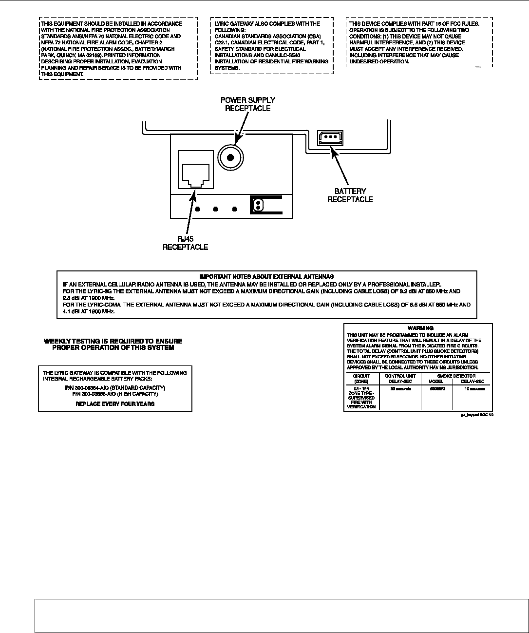
Lyric Controller Installation and Reference Guide
- 41 -
LYRIC GATEWAY RESIDENTIAL BURGLAR AND FIRE ALARM CONTROL PANEL
SUMMARY OF CONNECTIONS
Notes: Connection of the fire alarm signal to a fire alarm headquarters or a Central Station shall be permitted
with the approval of the local authority having jurisdiction. The burglar alarm signal shall not be connected to a
police emergency number. The System must be checked by a qualified technician once every three years
SUPPORT, WARRANTY, & PATENT INFORMATION
For the latest documentation and online support information, please go to:
https://mywebtech.honeywell.com/
For the latest warranty information, please go to:
www.honeywell.com/security/hsc/resources/wa.
For patent information, see www.honeywell.com/patents
MyWebTech
Warranty
Patents
2 Corporate Center Drive, Suite 100
P.O. Box 9040, Melville, NY 11747
Copyright © 2016 Honeywell International Inc.
www.honeywell.com/security
Ê800-21666UŠ
800-21666 10/16 Rev. A