user manual
INSTALL GUIDE
33-00135EFS-03
ERM5220R
Equipment Remote Module
WITH REDLINK™ WIRELESS TECHNOLOGY
Table of Contents
About the ERM5220R 2
Installation Checklist 3
Terminal Designations 4
Installation 6
Checkout 12
Troubleshooting 14
Specifications 16
5 Year Warranty 18
CAUTION
Read these installation instructions completely and follow them
carefully.
Installation must be performed by a qualified service technician and
must comply with local codes.
Disconnect power to all relevant devices before installing or
servicing the ERM.
Failure to connect the device according to these instructions may
result in damage to the device, the controls, and/or personal injury.
33-00135EFS_B.book Page 1 Wednesday, November 11, 2015 11:31 AM
33-00135EFS—03 2
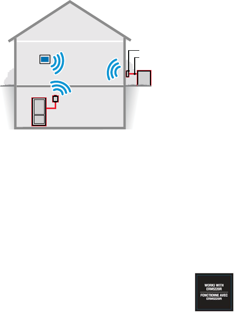
About the ERM5220R
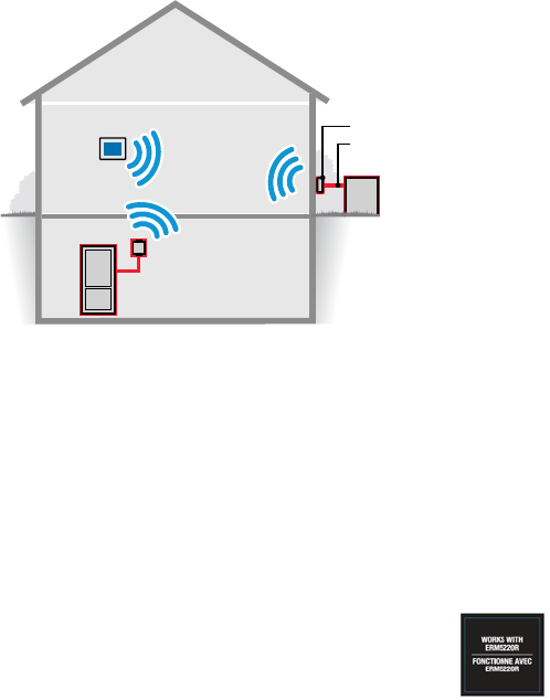
Fig. 1.
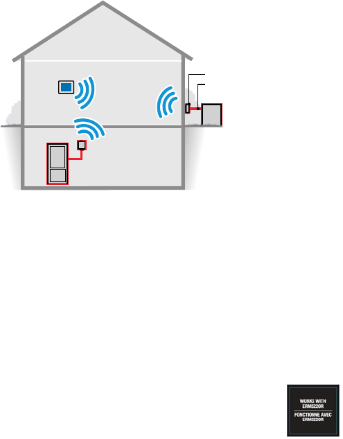
• Wireless RedLink™ communication between condensing unit/
compressor or boiler and thermostat.
• Eliminates the need to run additional wires to your equipment, for
example, during a heat pump upgrade.
• Suitable for outdoor use.
• Temperature sensor terminals for outdoor temp sensors or indoor
freeze protection.
• LEDs for easy installation checkout.
• May reduce damage to homes since wiring/drilling is eliminated.
NOTE: The ERM5220R must be used with updated
THX9421R5021, TH8321R1001 and/or EIM. Look
for this image on these products.
MCR35654
ERM
WIRE
CONDENSING
UNIT
THERMOSTAT
ERM
BOILER
33-00135EFS_B.book Page 2 Wednesday, November 11, 2015 11:31 AM
3 33-00135EFS—03
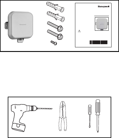
Installation Checklist
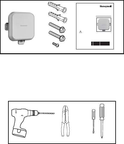
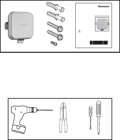
MATERIALS SUPPLIED:
• ERM5220R
• Wall Anchors (x2) and Mounting Screws (x2)
• Extra Cover Screw (optional)
• Installation Instructions
TOOLS NEEDED (NOT SUPPLIED):
•Drill
• Nut Driver Attachment for Drill
• Wire Stripper
• Small Flathead Screwdriver
• Phillips Screwdriver
• 120/240 V to 24 V Transformer (optional)
M35671
INSTALL GUIDE
33-00135EFS-03
ERM5220R
Equipment Remote Module
WITH REDLINK™ WIRELESS TECHNOLOGY
Table of Contents
About the ERM5220R 2
Installation Checklist 3
Terminal Designations 4
Installation 6
Checkout 12
Troubleshooting 14
Specifications 16
5 Year Warranty 18
CAUTION
Read these installation instructions completely and follow them
carefully.
Installation must be performed by a qualified service technician and
must comply with local codes.
Disconnect power to all relevant devices before installing or
servicing the ERM.
Failure to connect the device according to these instructions may
result in damage to the device, the controls, and/or personal injury.
M35669 M35672
M35670
33-00135EFS_B.book Page 3 Wednesday, November 11, 2015 11:31 AM

33-00135EFS—03 4
Terminal Designations
Fig. 2. Terminal Designations for Compressor.
M35655
JRCYDLS1 S1
TERMINALS FOR 10K OHM TEMPERATURE SENSOR. CAN BE USED TO SENSE OUTDOOR TEMPERATURES WHICH WILL BE DISPLAYED
ON A COMPATIBLE RedLINK THERMOSTAT.
COMPRESSOR LINE FAULT TERMINAL. FAULT OCCURRENCE WILL BE COMMUNICATED TO COMPATIBLE RedLINK THERMOSTAT.
COMPRESSOR DEFROST TERMINAL. DEFROST OCCURRENCE WILL BE COMMUNICATED TO COMPATIBLE RedLINK THERMOSTAT.
O/B TERMINAL FOR REVERSING VALVE ON HEAT PUMP.
SECOND STAGE OF TWO STAGE COMPRESSOR.
FIRST STAGE OF TWO STAGE COMPRESSOR.
TERMINALS FOR 24VAC POWER.
TERMINAL FOR JUMPER. JUMPER BETWEEN J AND R SHOULD BE IN PLACE FOR COMPRESSOR USE.
THE “D” TERMINAL OPERATES AS AN INPUT FOR DEFROST. ACTIVE INPUT ON “D” TERMINAL WILL POWER AUX1. IF “D” TO AUX1 IS NOT DESIRED, DO NOT
CONNECT “D” TERMINAL TO THE ERM5220R. THIS FEATURE IS ONLY ACTIVE WHEN THE THE ERM5220R IS CONFIGURED FOR USE WITH A COMPRESSOR
TERMINAL DESIGNATIONS FOR COMPRESSOR
O/B
T
Y2
T
1
1
33-00135EFS_B.book Page 4 Wednesday, November 11, 2015 11:31 AM

5 33-00135EFS—03
Fig. 3. Terminal Designations for Boiler.
M35656A
JRCYO/B
TDLS1 S1
TERMINALS FOR 10K OHM TEMPERATURE SENSOR. CAN BE USED FOR FREEZE PROTECTION IN THE CASE OF THE THERMOSTAT
LOSING THE SIGNAL TO THE ERM. SENSOR MUST REMAIN INDOORS TO BE USED FOR FREEZE PROTECTION.
TERMINAL FOR HEAT CALL.
TERMINALS FOR 24VAC POWER.
TERMINAL FOR JUMPER. JUMPER BETWEEN J AND R SHOULD BE REMOVED FOR BOILER USE.
TERMINAL DESIGNATIONS FOR BOILER
Y2
T
TERMINAL FOR HEAT CALL.
NOTE: ERM WILL NOT SUPPORT SERIES20 OPERATION. WHEN CONFIGURED AS A BOILER, THE Y RELAY SHALL BE OFF AT ALL TIMES.
33-00135EFS_B.book Page 5 Wednesday, November 11, 2015 11:31 AM
33-00135EFS—03 6
INSTALLATION
IMPORTANT
• The ERM is not compatible with RedLink Zone boards.
• To ensure that the ERM will receive a wireless signal at the
desired installation location, follow steps 1 to 5 in the Wiring
section.
• If your location has metal siding, the ERM’s signal may be
affected. If there is no communication or poor signal strength,
consider a different location.
• A Prestige (with EIM) or VisionPRO (with or without EIM) will
only allow one of the following configurations:
1) Enrolled with a single boiler configured ERM;
2) Enrolled with a single compressor configured ERM;
3) Enrolled with a single boiler configured ERM and enrolled
with a single compressor configured ERM.
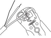
Wiring
1. Make sure power to compressor/boiler is off.
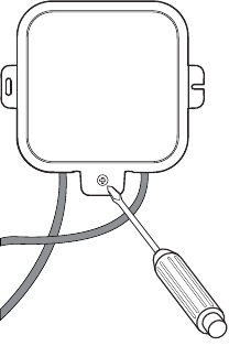
2. Remove the front cover by loosening the cover screw and lifting up
from the bottom of the ERM.
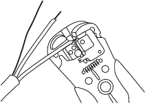
3. Remove 3 to 4 inches of the cable’s outer sheathing, then remove
3/8 to 1/2 inch of insulation from each wire.
Fig. 4. Cable prepared for wiring.
M35674
33-00135EFS_B.book Page 6 Wednesday, November 11, 2015 11:31 AM

7 33-00135EFS—03
4. For compressor applications: Leave the jumper between termi-
nals J and R in place.
For boiler applications: Remove the jumper between terminals J
and R.
Fig. 5. Terminal Designations showing the jumper
between J and R terminals.
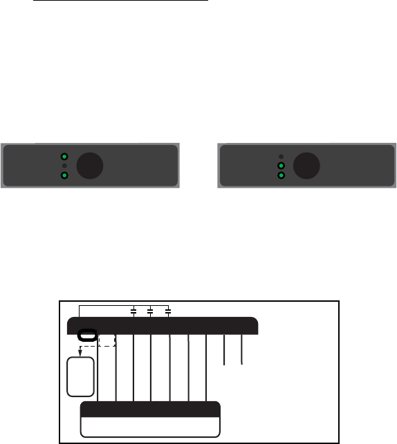
5. For compressors and boilers: Connect a 24 VAC power source
to the R and C terminals on the ERM.
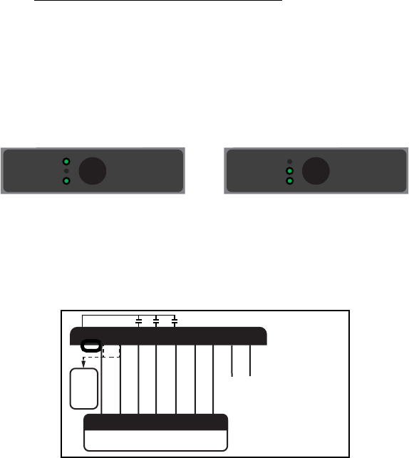
Fig. 6.
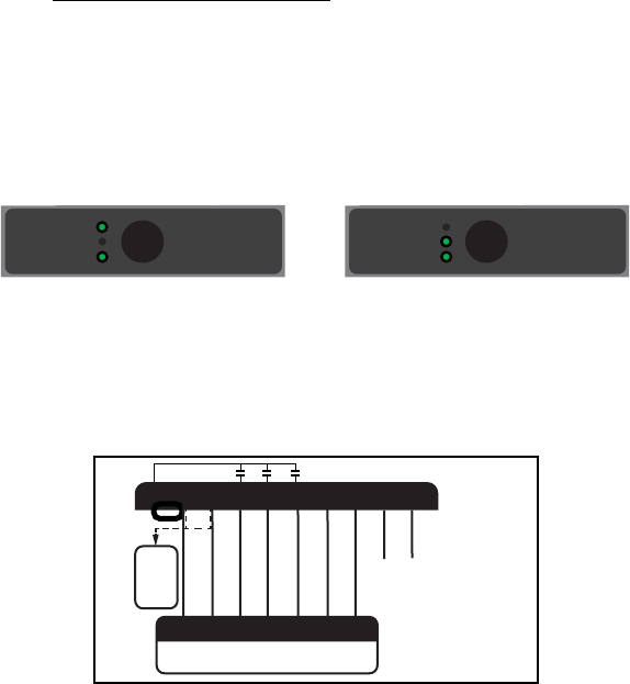
Once power is connected, the “Compressor” (or “Boiler”) LED should
illuminate green. (Fig. 7)
Fig. 7.
MCR35657
CYDLS1 S1
FOR COMPRESSOR:
Jumper J and R
FOR BOILER:
Remove Jumper
JRO/B
T
Y2
T
M35658
CYDLS1 S1
24V CAN COME FROM AIR HANDLER
(COMPRESSOR APPLICATION)
OR EXTERNAL TRANSFORMER
JRO/B
T
Y2
T
24
VAC
V c.a.
OR
MCR35659
CONNECTED LED STATUS
Connect
Flashing: Device Connecting
Green: Device Connected
Red: Not Communicating
Compressor
Boiler
Connected
MCR35660
CONNECTED LED STATUS
Connect
Flashing: Device Connecting
Green: Device Connected
Red: Not Communicating
Compressor
Boiler
Connected
33-00135EFS_B.book Page 7 Wednesday, November 11, 2015 11:31 AM
33-00135EFS—03 8
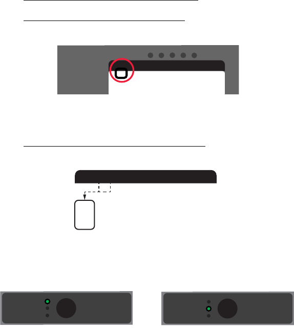
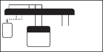
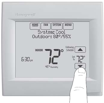
6. For compressors and boilers: Put the thermostat in pairing
mode by selecting “add a device” from the installer menu. See
thermostat manual for further details. Once the thermostat is in
pairing mode, press and quickly release the “Connect” button on
the ERM.
When the ERM is connected to the system, the ERM’s “Con-
nected” LED will be solid green and the thermostat will show
“ERM” in its Wireless Manager. (Fig. 8)
Fig. 8.
7. Connect terminals from the ERM to the appropriate terminals on
the compressor/boiler control board.
COMPRESSOR
Fig. 9.
OR
MCR35661
CONNECTED LED STATUS
Connect
Flashing: Device Connecting
Green: Device Connected
Red: Not Communicating
Compressor
Boiler
Connected
MCR35662
CONNECTED LED STATUS
Connect
Flashing: Device Connecting
Green: Device Connected
Red: Not Communicating
Compressor
Boiler
Connected
M35668
CYDLS1 S1
JRO/B
T
Y2
T
CYDL
R
Y2 O/B
24
VAC
V c.a.
10K OHM OUTDOOR
TEMPERATURE
SENSOR (OPTIONAL)
EQUIPMENT CONTROL BOARD
33-00135EFS_B.book Page 8 Wednesday, November 11, 2015 11:31 AM
9 33-00135EFS—03
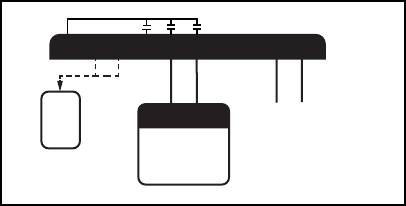
BOILER
Fig. 10.
IMPORTANT
If the ERM was previously used with a compressor and will now
be used with a boiler:
1) un-enroll the ERM at the thermostat;
2) remove the jumper on the ERM;
3) designate Radiant Heat for Heating System Type
(ISU 2000) in your thermostat.
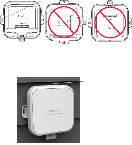
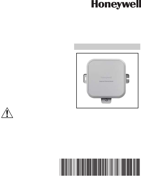
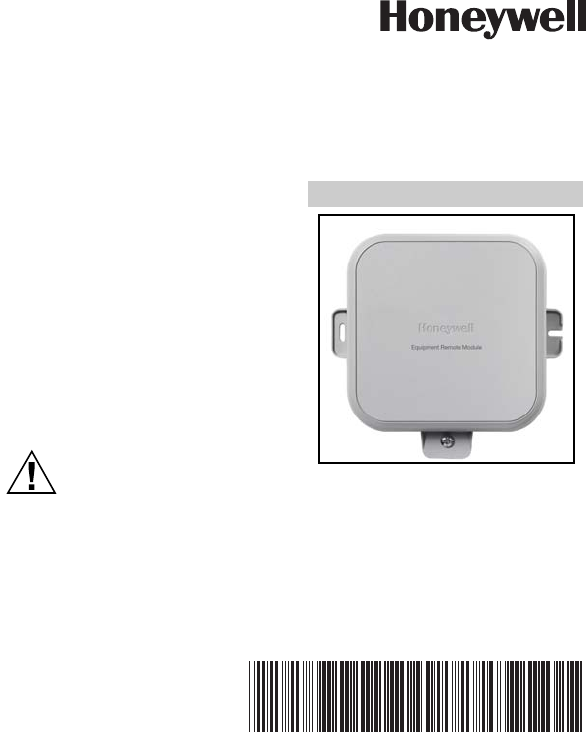
Mounting ERM
8. Use two screws and wall anchors to attach the ERM to the exterior
wall near the compressor. The location should be at least 3 feet
above ground and oriented with the two wire exits facing
downward. See Figs. 11 and 12.
M35673
CYDLS1 S1
JRO/B
T
Y2
T
T
EQUIPMENT
CONTROL
BOARD
10K OHM INDOOR
TEMPERATURE
SENSOR
(RECOMMENDED)
T
24
VAC
V c.a.
33-00135EFS_B.book Page 9 Wednesday, November 11, 2015 11:31 AM
33-00135EFS—03 10
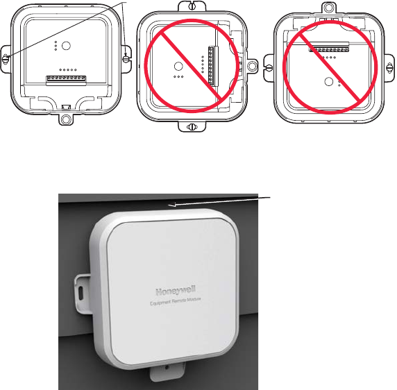
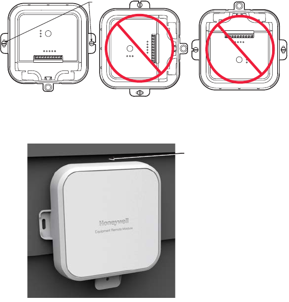
9. Attach cover and secure with bottom screw (Fig. 13).
Fig. 11. Mounting orientation.
Fig. 12. If mounting on lap siding,
allow space for the cover to be removed.
MCR35665
MOUNTING
SCREWS
CORRECT
Equipment Remote Module I ERM5000R
Compressor
Boiler
Connected
Connect
CONNECTED LED STATUS
Flashing: Device Connecting
Green: Device Connected
Red: Not Communicating
Compressor:
Jump J and R
Boiler:
Remove Jumper
JRC
Y1
Y2
TO/B
T
DL
S1 S1
INCORRECTINCORRECT
Equipment Remote Module I ERM5000R
Compressor
Boiler
Connected
Connect
CONNECTED LED STATUS
Flashing: Device Connecting
Green: Device Connected
Red: Not Communicating
Compressor:
Jump J and R
Boiler:
Remove Jumper
JRC
Y1
Y2
TO/B
T
DL
S1 S1
Equipment Remote Module I ERM5000R
Compressor
Boiler
Connected
Connect
CONNECTED LED STATUS
Flashing: Device Connecting
Green: Device Connected
Red: Not Communicating
Compressor:
Jump J and R
Boiler:
Remove Jumper
JRC
Y1
Y2
TO/B
T
DL
S1 S1
M35666
MINIMUM
1/4 INCH GAP
33-00135EFS_B.book Page 10 Wednesday, November 11, 2015 11:31 AM

11 33-00135EFS—03
Fig. 13.
M35667
33-00135EFS_B.book Page 11 Wednesday, November 11, 2015 11:31 AM
33-00135EFS—03 12
Checkout
Power the system on. Use the thermostat to start a cooling or heating
cycle, testing the ERM.
1. Restore power to the compressor/boiler as well as your RedLink
system.
2. Raise/lower the set point on the zone thermostat to initiate a call
for heat/cooling.
3. Observe all control devices to ensure operation and heat/cooling is
active.
4. Lower/raise the set point on the thermostat to suspend the call for
heat/cooling.
5. If outdoor temperature sensor is used, check thermostat to see the
readings are active and accurate.
6. Be sure to set thermostat to the desired settings when checkout is
complete.
33-00135EFS_B.book Page 12 Wednesday, November 11, 2015 11:31 AM

13 33-00135EFS—03
Fig. 14.
M35680
33-00135EFS_B.book Page 13 Wednesday, November 11, 2015 11:31 AM

33-00135EFS—03 14
TROUBLESHOOTING
NOTE: Disconnect RedLink™ when making changes to the
device.
RESET PROCEDURE:
Hold down the “Connect” button on the ERM for 10 seconds. The
“Connection” LED should appear red for a few seconds and go out. This
indicates the unit is reset.
Symptom Possible Cause Action
Relays don’t switch as
expected Incorrect jumper
configuration Check jumper
configuration. If
incorrect, unenroll
from system, change
jumper, then re-enroll
with system.
Connected LED is red Loss of
communication with
system
Verify thermostat and/
or Equipment Interface
Module are powered
and functioning
correctly.
Connected LED is off Device is not enrolled
with system Enroll with system.
No LEDs are on No power to device Verify 24 VAC at R/C
terminals.
33-00135EFS_B.book Page 14 Wednesday, November 11, 2015 11:31 AM

15 33-00135EFS—03
No outdoor
temperature shown on
thermostat
No wired outdoor
temperature sensor
connected to ERM, or
device configured as
boiler
Connect outdoor
temperature sensor to
S1/S1 terminals.
Device only reports
outdoor temperature
temperature when
configured as
compressor.
Thermostat shows “—”
for outdoor
temperature
Wired outdoor
temperature sensor
failed
Check sensor for short
circuit or open circuit.
Outdoor temperature
reading at thermostat
is too high
Sun load on sensor Verify outdoor
temperature sensor is
not in direct sunlight.
May need to use
longer wire to mount in
ideal location.
Compressor doesn’t
turn on, “Y” LED is
blinking
5-minute compressor
lockout after power
cycle
Wait 5 minutes,
compressor will turn
on after safety timeout.
Emergency backup
control doesn’t function
(if configured as boiler)
No valid indoor
temperature sensor Check sensor for short
circuit or open circuit,
or install indoor
temperature sensor on
S1/S1 terminals.
Symptom Possible Cause Action
33-00135EFS_B.book Page 15 Wednesday, November 11, 2015 11:31 AM

33-00135EFS—03 16
SPECIFICATIONS
Operating Ambient Temperature Range:
Compressor: -40 to +155 ºF (-40 to +68 ºC)
Boiler: 30 to +130 ºF (-1 to +54 ºC)
Operating Relative Humidity Range: 0 - 99 %
Electrical:
24 VAC, 50/60 Hz.
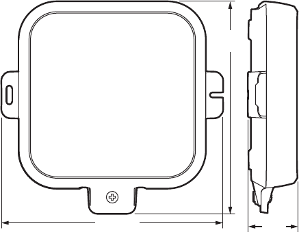
Dimensions:
175 mm x 168 mm x 38 mm
Wireless capability via RedLink™ technology.
Fig. 15. Dimensions.
M35664
6-7/8 (175)
6-39/64
(168)
1-31/64
(38)
33-00135EFS_B.book Page 16 Wednesday, November 11, 2015 11:31 AM
17 33-00135EFS—03
SEPARABLE PARTS
ERM with TH8321R1001/U: YERM5220R8321
ERM with TH8321R1001/U and THM5421R1021: YERM5220RVPEIM
FCC REGULATIONS
§ 15.19 (a)(3)
This device complies with part 15 of the FCC Rules. Operation is subject
to the following two conditions:
1. This device may not cause harmful interference, and
2. this device must accept any interference received, including
interference that may cause undesired operation.
IC REGULATIONS
RSS-GEN
This device complies with Industry Canada’s licence-exempt RSSs.
Operation is subject to the following two conditions:
1. This device may not cause interference; and
2. This device must accept any interference, including interference
that may cause undesired operation of the device.
33-00135EFS_B.book Page 17 Wednesday, November 11, 2015 11:31 AM
FCC Warning (Part 15.21) (USA only)
Changes or modifications not expressly approved by the party
responsible for compliance could void the user’s authority to operate
the equipment.
33-00135EFS—03 18
5 YEAR WARRANTY
Honeywell warrants this product to be free from defects in the workmanship or
materials, under normal use and service, for a period of five (5) years from the
date of purchase by the consumer. If at any time during the warranty period the
product is determined to be defective or malfunctions, Honeywell shall repair or
replace it (at Honeywell's option).
If the product is defective,
(i) return it, with a bill of sale or other dated proof of purchase, to the place from
which you purchased it; or
(ii) call Honeywell Customer Care at 1-800-468-1502. Customer Care will make
the determination whether the product should be returned to the following
address: Honeywell Return Goods, Dock 4 MN10-3860, 1985 Douglas Dr. N.,
Golden Valley, MN 55422, or whether a replacement product can be sent to you.
This warranty does not cover removal or reinstallation costs. This warranty shall
not apply if it is shown by Honeywell that the defect was caused by damage which
occurred while the product was in the possession of a consumer.
Honeywell’s sole responsibility shall be to repair or replace the product within the
terms stated above. HONEYWELL SHALL NOT BE LIABLE FOR ANY LOSS OR
DAMAGE OF ANY KIND, INCLUDING ANY INCIDENTAL OR CONSEQUENTIAL
DAMAGES RESULTING, DIRECTLY OR INDIRECTLY, FROM ANY BREACH OF
ANY WARRANTY, EXPRESS OR IMPLIED, OR ANY OTHER FAILURE OF THIS
PRODUCT. Some states do not allow the exclusion or limitation of incidental or
consequential damages, so this limitation may not apply to you.
THIS WARRANTY IS THE ONLY EXPRESS WARRANTY HONEYWELL MAKES
ON THIS PRODUCT. THE DURATION OF ANY IMPLIED WARRANTIES,
INCLUDING THE WARRANTIES OF MERCHANTABILITY AND FITNESS FOR A
PARTICULAR PURPOSE, IS HEREBY LIMITED TO THE FIVE-YEAR
DURATION OF THIS WARRANTY.
Some states do not allow limitations on how long an implied warranty lasts, so the
above limitation may not apply to you. This warranty gives you specific legal rights,
and you may have other rights which vary from state to state.
If you have any questions concerning this warranty, please write Honeywell
Customer Care, 1985 Douglas Dr, Golden Valley, MN 55422 or call 1-800-468-
1502.
33-00135EFS_B.book Page 18 Wednesday, November 11, 2015 11:31 AM
19 33-00135EFS—03
33-00135EFS_B.book Page 19 Wednesday, November 11, 2015 11:31 AM

Automation and Control Solutions
Honeywell International Inc.
1985 Douglas Drive North
Golden Valley, MN 55422
yourhome.honeywell.com
® U.S. Registered Trademark
© 2015 Honeywell International Inc.
33-00135EFS—03 M.S. 11-15
Printed in United States
33-00135EFS_B.book Page 20 Wednesday, November 11, 2015 11:31 AM
GUIDE D’INSTALLATION
33-00135EFS-03
ERM5220R
Module d'équipement à distance (ERM)
AVEC TECHNOLOGIE SANS FIL REDLINK™
Table des matières
À propos du module ERM5220R 2
Liste de vérification pour l’installation 3
Désignations des bornes 4
Installation 6
Vérification 12
Dépannage 14
Caractéristiques 16
Garantie de 5 ans 18
MISE EN GARDE
Lire cette notice d'installation dans son intégralité et bien respecter
les instructions.
L’installation doit être effectuée par un technicien d’entretien
qualifié et conformément aux codes locaux en vigueur.
Couper l’alimentation vers l’appareil avant d’installer ou de réparer
ce module ERM.
Un raccordement de cet appareil non conforme à ces instructions
peut endommager l’appareil ou les régulateurs et causer des
blessures.
33-00135EFS_B.book Page 1 Wednesday, November 11, 2015 11:31 AM
33-00135EFS—03 2
À propos du module ERM5220R
Fig. 1.
• Communication sans fil RedLink™ entre le unité de
condensation/compresseur ou la chaudière et le thermostat.
• Élimine la nécessité d'acheminer des fils supplémentaires vers
l'équipement, pour la mise à niveau d'une thermopompe par exemple.
• Compatible avec une utilisation à l'extérieur.
• Bornes de capteur de température pour capteurs de température
extérieure ou protection antigel intérieure.
• Témoins DEL pour une vérification aisée de l'installation.
• L'absence de câblage et de perçage peut minimiser les dommages
de l'habitation.
REMARQUE : Le module ERM5220R doit être utilisé
avec les dispositifs THX9421R5021,
TH8321R1001 ou un module d'interface
d'équipement (EIM) mis à jour. Rechercher
cette image sur ces produits.
MFCR35654
MODULE ERM
FIL
UNITÉ DE
CONDENSATION
THERMOSTAT
MODULE ERM
CHAUDIÈRE
33-00135EFS_B.book Page 2 Wednesday, November 11, 2015 11:31 AM
3 33-00135EFS—03
Liste de vérification pour l’installation
MATÉRIEL FOURNI :
• ERM5220R
• Ancres murales (2) et vis de montage (2)
• Vis de couvercle supplémentaire (en option)
• Notice d'installation
OUTILS REQUIS (NON FOURNIS) :
• Perceuse
• Douille tourne-écrou pour la perceuse
• Dénudeur de fils
• Petit tournevis plat
• Tournevis cruciforme
• Transformateur 120/240 V à 24 V (en option)
M35671
INSTALL GUIDE
33-00135EFS-03
ERM5220R
Equipment Remote Module
WITH REDLINK™ WIRELESS TECHNOLOGY
Table of Contents
About the ERM5220R 2
Installation Checklist 3
Terminal Designations 4
Installation 6
Checkout 12
Troubleshooting 14
Specifications 16
5 Year Warranty 18
CAUTION
Read these installation instructions completely and follow them
carefully.
Installation must be performed by a qualified service technician and
must comply with local codes.
Disconnect power to all relevant devices before installing or
servicing the ERM.
Failure to connect the device according to these instructions may
result in damage to the device, the controls, and/or personal injury.
M35669 M35672
M35670
33-00135EFS_B.book Page 3 Wednesday, November 11, 2015 11:31 AM

33-00135EFS—03 4
Désignations des bornes
Fig. 2. Désignations des bornes pour le compresseur.
MF35655
JRCYDLS1 S1
BORNES POUR CAPTEUR DE TEMPÉRATURE 10 K OHMS. PEUVENT ÊTRE UTILISÉES POUR DÉTECTER LES TEMPÉRATURES EXTÉRIEURES
QUI SERONT AFFICHÉES SUR UN THERMOSTAT RedLINK COMPATIBLE.
BORNE DE DÉFAILLANCE DE LIGNE DU COMPRESSEUR. L'OCCURRENCE DE LA DÉFAILLANCE SERA COMMUNIQUÉE AU THERMOSTAT RedLINK COMPATIBLE.
BORNE DE DÉGIVRAGE DU COMPRESSEUR. L'OCCURRENCE DU DÉGIVRAGE SERA COMMUNIQUÉE AU THERMOSTAT RedLINK COMPATIBLE.
BORNE O/B POUR LA VANNE D'INVERSION DE LA THERMOPOMPE.
DEUXIÈME ÉTAGE DU COMPRESSEUR À DEUX ÉTAGES.
PREMIER ÉTAGE DU COMPRESSEUR À DEUX ÉTAGES.
BORNES POUR ALIMENTATION 24 V C.A.
BORNE POUR CAVALIER. LE CAVALIER ENTRE J ET R DOIT ÊTRE EN PLACE POUR L'APPLICATION AVEC COMPRESSEUR.
LA BORNE D SERT D'ENTRÉE POUR LE DÉGIVRAGE. L'ENTRÉE ACTIVE SUR LA BORNE D ALIMENTE AUX1. SI CELA N'EST PAS SOUHAITÉ, NE PAS
BRANCHER LA BORNE D AU MODULE ERM5220R. CETTE FONCTION N'EST ACTIVE QUE LORSQUE LE MODULE ERM5220R EST CONFIGURÉ
POUR UNE UTILISATION AVEC UN COMPRESSEUR.
D
É
SIGNATIONS DES BORNES POUR LE COMPRESSEUR
O/B
T
Y2
T
1
1
33-00135EFS_B.book Page 4 Wednesday, November 11, 2015 11:31 AM

5 33-00135EFS—03
Fig. 3. Désignations des bornes pour la chaudière.
MF35656A
JRCYO/B
TDLS1 S1
BORNES POUR CAPTEUR DE TEMPÉRATURE 10 K OHMS. PEUT ÊTRE UTILISÉ POUR LA PROTECTION CONTRE LE GEL EN CAS
DE PERTE DE SIGNAL ENTRE LE THERMOSTAT ET LE MODULE ERM. LE CAPTEUR DOIT RESTER À L'INTÉRIEUR POUR ÊTRE
UTILISÉ COMME PROTECTION CONTRE LE GEL.
BORNE POUR APPEL DE CHAUFFAGE.
BORNES POUR ALIMENTATION 24 V C.A.
BORNE POUR CAVALIER. LE CAVALIER ENTRE J ET R DOIT ÊTRE RETIRÉ POUR L'APPLICATION AVEC CHAUDIÈRE.
DÉSIGNATIONS DES BORNES POUR LA CHAUDIÈRE
Y2
T
BORNE POUR APPEL DE CHAUFFAGE.
REMARQUE : L'ERM N'EST PAS COMPATIBLE AVEC LA SÉRIE 20. POUR LES APPLICATIONS AVEC CHAUDIÈRE, LE RELAIS Y EST
DÉSACTIVÉ EN PERMANENCE.
33-00135EFS_B.book Page 5 Wednesday, November 11, 2015 11:31 AM
33-00135EFS—03 6
INSTALLATION
IMPORTANT
• Le module ERM n'est pas compatible avec les tableaux de zone
RedLink.
• Pour s'assurer que le module ERM recevra un signal sans fil à
l'emplacement souhaité pour l'installation, suivre les étapes 1 à 5 de la
section Câblage.
• Si l'emplacement comporte un bardage métallique, le signal de l'ERM
peut en être affecté. En cas d'absence de communication ou d'intensité
insuffisante du signal, considérer un autre emplacement.
• Les thermostats Prestige (avec EIM) ou VisionPRO (avec ou sans EIM)
ne permettront que l'une des configurations suivantes :
1) Enregistrement avec un ERM configuré pour une seule chaudière;
2) Enregistrement avec un ERM configuré pour un seul compresseur;
3) Enregistrement avec un ERM configuré pour une seule chaudière
et enregistrement avec un ERM configuré pour un seul compresseur.
Câblage
1. S'assurer que l'alimentation vers le compresseur/la chaudière est
coupée.
2. Retirer le couvercle avant en desserrant la vis du couvercle et en le
relevant du bas de l'ERM.
3. Retirer 3 à 4 pouces de la gaine extérieure du câble, puis retirer
3/8 à 1/2 pouce d'isolation de chaque fil.
Fig. 4. Câble préparé pour le raccordement.
M35674
33-00135EFS_B.book Page 6 Wednesday, November 11, 2015 11:31 AM
7 33-00135EFS—03
4. Pour les applications avec compresseur : Laisser le cavalier en
place entre les bornes J et R.
Pour les applications avec chaudière : Retirer le cavalier entre
les bornes J et R.
Fig. 5. Désignations des bornes montrant
le cavalier entre les bornes J et R.
5. Pour les compresseurs et les chaudières : Brancher une source
d'alimentation de 24 V c.a. sur les bornes R et C du module ERM.
Fig. 6.
Une fois l'alimentation connectée, le témoin DEL « Compressor »
(Compresseur) ou « Boiler » (Chaudière) devrait s'allumer en vert. (Fig. 7)
Fig. 7.
MCR35657
CYDLS1 S1
FOR COMPRESSOR:
Jumper J and R
FOR BOILER:
Remove Jumper
JRO/B
T
Y2
T
MF35658
CYDLS1 S1
24 V PROVENANT DU SYSTÈME DE
TRAITEMENT DE L'AIR (APPLICATION
AVEC COMPRESSEUR) OU D'UN
TRANSFORMATEUR EXTERNE
JRO/B
T
Y2
T
24
V c.a.
OU
MCR35659
CONNECTED LED STATUS
Connect
Flashing: Device Connecting
Green: Device Connected
Red: Not Communicating
Compressor
Boiler
Connected
MCR35660
CONNECTED LED STATUS
Connect
Flashing: Device Connecting
Green: Device Connected
Red: Not Communicating
Compressor
Boiler
Connected
33-00135EFS_B.book Page 7 Wednesday, November 11, 2015 11:31 AM
33-00135EFS—03 8
6. Pour les compresseurs et les chaudières : Mettre le thermostat
en mode d'appairage en sélectionnant « Add a device » (Ajouter
un appareil) dans le menu de l'installateur. Consulter le manuel du
thermostat pour plus de détails. Une fois le thermostat en mode
d'appairage, appuyer rapidement sur le bouton « Connect »
(Connexion) sur le module ERM.
Une fois le module ERM connecté au système, son témoin DEL de
connexion s'allume en vert en continu et le thermostat indique
« ERM » dans le gestionnaire des dispositifs sans fil. (Fig. 8)
Fig. 8.
7. Connecter les bornes du module ERM aux bornes appropriées du
tableau de contrôle du compresseur/de la chaudière.
COMPRESSEUR
Fig. 9.
OU
MCR35661
CONNECTED LED STATUS
Connect
Flashing: Device Connecting
Green: Device Connected
Red: Not Communicating
Compressor
Boiler
Connected
MCR35662
CONNECTED LED STATUS
Connect
Flashing: Device Connecting
Green: Device Connected
Red: Not Communicating
Compressor
Boiler
Connected
MF35668
CYDLS1 S1
JRO/B
T
Y2
T
CYDL
R
Y2 O/B
24
V c.a. CAPTEUR DE TEMPÉRATURE
EXTÉRIEURE 10 K OHMS
(EN OPTION)
TABLEAU DE CONTRÔLE
DE L'ÉQUIPEMENT
33-00135EFS_B.book Page 8 Wednesday, November 11, 2015 11:31 AM

9 33-00135EFS—03
CHAUDIÈRE
Fig. 10.
IMPORTANT
Si le module ERM a précédemment été utilisé avec un compresseur
et est maintenant destiné à être utilisé avec une chaudière :
1) annuler l'enregistrement du module ERM sur le thermostat;
2) retirer le cavalier du module ERM;
3) indiquer Radiant Heat for Heating System Type (ISU 2000)
(Chauffage rayonnant pour type de système de chauffage) sur
le thermostat.
Montage du module ERM
8. Utiliser deux vis et deux ancres murales pour fixer le module ERM
sur le mur extérieur près du compresseur. L'emplacement doit être
situé à au moins 3 pieds au-dessus du sol et orienté avec les
deux sorties de fil face vers le bas. Voir les Figs. 11 et 12.
MF35673
CYDLS1 S1
JRO/B
T
Y2
T
T
TABLEAU DE
CONTRÔLE DE
L'ÉQUIPEMENT
CAPTEUR DE TEMPÉRATURE
INTÉRIEURE 10 K OHMS
(RECOMMANDÉ)
T
24
V c.a.
33-00135EFS_B.book Page 9 Wednesday, November 11, 2015 11:31 AM
33-00135EFS—03 10
9. Attacher le couvercle et le fixer avec la vis inférieure (Fig. 13).
Fig. 11. Orientation de montage.
Fig. 12. Si le montage a lieu sur un bardage à clin, laisser
suffisamment d'espace pour permettre le retrait du couvercle.
MFCR35665
VIS DE MONTAGE
CORRECTE
Equipment Remote Module I ERM5000R
Compressor
Boiler
Connected
Connect
CONNECTED LED STATUS
Flashing: Device Connecting
Green: Device Connected
Red: Not Communicating
Compressor:
Jump J and R
Boiler:
Remove Jumper
JRC
Y1
Y2
TO/B
T
DL
S1 S1
INCORRECTEINCORRECTE
Equipment Remote Module I ERM5000R
Compressor
Boiler
Connected
Connect
CONNECTED LED STATUS
Flashing: Device Connecting
Green: Device Connected
Red: Not Communicating
Compressor:
Jump J and R
Boiler:
Remove Jumper
JRC
Y1
Y2
TO/B
T
DL
S1 S1
Equipment Remote Module I ERM5000R
Compressor
Boiler
Connected
Connect
CONNECTED LED STATUS
Flashing: Device Connecting
Green: Device Connected
Red: Not Communicating
Compressor:
Jump J and R
Boiler:
Remove Jumper
JRC
Y1
Y2
TO/B
T
DL
S1 S1
ESPACEMENT
MINIMUM 1/4 PO
33-00135EFS_B.book Page 10 Wednesday, November 11, 2015 11:31 AM

11 33-00135EFS—03
Fig. 13.
M35667
33-00135EFS_B.book Page 11 Wednesday, November 11, 2015 11:31 AM
33-00135EFS—03 12
Vérification
Mettre le système sous tension. Utiliser le thermostat pour lancer un
cycle de chauffage ou de refroidissement pour tester le module ERM.
1. Restaurer l'alimentation vers le compresseur/la chaudière ainsi
que vers le système RedLink.
2. Hausser/réduire le point de consigne sur le thermostat de zone
pour lancer un appel de chauffage/refroidissement.
3. Observer tous les dispositifs de régulation pour vérifier qu'ils
fonctionnent bien et que le chauffage/refroidissement est actif.
4. Réduire/hausser le point de consigne sur le thermostat pour lancer
un appel de chauffage/refroidissement.
5. Si le capteur de température extérieure est utilisé, vérifier que les
valeurs indiquées sur le thermostat sont actives et précises.
6. Veiller à régler le thermostat aux réglages désirés une fois la
vérification terminée.
33-00135EFS_B.book Page 12 Wednesday, November 11, 2015 11:31 AM

13 33-00135EFS—03
Fig. 14.
M35680
33-00135EFS_B.book Page 13 Wednesday, November 11, 2015 11:31 AM

33-00135EFS—03 14
DÉPANNAGE
REMARQUE : Débrancher le système RedLink™ avant de procéder
à des modifications sur le dispositif.
PROCÉDURE DE RÉINTIALISATION :
Appuyer pendant 10 secondes sur le bouton « Connect » (Connexion)
du module ERM. Le témoin DEL de connexion doit s'allumer en rouge
pendant quelques secondes, puis s'éteindre. Ceci indique que l'unité a
été réinitialisée.
Symptôme Cause possible Action
Les relais ne
s'enclenchent pas
comme prévu
Configuration
incorrecte du cavalier Contrôler la configuration
du cavalier. Si elle est
incorrecte, annuler
l'enregistrement, modifier
le cavalier, puis
enregistrer de nouveau
l'appareil.
Le témoin DEL de
connexion est rouge Perte de
communication avec le
système
Vérifier que le thermostat
et/ou le module
d'interface d'équipement
sont alimentés et
fonctionnent
correctement.
Le témoin DEL de
connexion est éteint L'appareil n'est pas
enregistré dans le
système
Enregistrer l'appareil
dans le système.
Aucun témoin DEL
n'est allumé L'appareil n'est pas
alimenté Vérifier que 24 V c.a. sont
présents aux bornes R/C.
33-00135EFS_B.book Page 14 Wednesday, November 11, 2015 11:31 AM

15 33-00135EFS—03
Le thermostat
n'affiche pas la
température
extérieure
Aucun capteur de
température extérieure
n'est connecté au
module ERM, ou
l'appareil est configuré
sur chaudière
Brancher le capteur de
température extérieur aux
bornes S1/S1.
L'appareil n'indique que
la température extérieure
lorsqu'il est configuré sur
compresseur.
Le thermostat
indique « — » pour
la température
extérieure
Défaillance du capteur
de température
extérieure avec fil
Contrôler le capteur pour
s'assurer qu'il n'y a ni
court-circuit ni circuit
ouvert.
La température
extérieure indiquée
sur le thermostat est
trop élevée
Charge solaire sur le
capteur Vérifier que le capteur de
température extérieure
n'est pas directement
exposé à la lumière
solaire. Un fil plus long
peut être requis pour
assurer une installation
adéquate.
Le compresseur ne
se met pas en
marche, le témoin
DEL « Y » clignote
Verrouillage du
compresseur de 5
minutes après le cycle
de mise sous tension
Attendre 5 minutes. Le
compresseur se met en
marche après le délai de
sécurité.
La régulation de
secours en cas
d'urgence ne
fonctionne pas (si
configurée comme
chaudière)
Pas de capteur de
température intérieure
valide
Contrôler le capteur pour
vérifier qu'il n'y a pas de
court-circuit ni de circuit
ouvert, ou installer le
capteur de température
intérieure sur les bornes
S1/S1.
Symptôme Cause possible Action
33-00135EFS_B.book Page 15 Wednesday, November 11, 2015 11:31 AM

33-00135EFS—03 16
CARACTÉRISTIQUES
Gamme de température ambiante de service :
Compresseur : -40 à +68 °C (-40 à +155 °F)
Chaudière : -1 à +54 °C (30 à +130 °F)
Plage d'humidité relative de service : 0 - 99 %
Spécifications électriques :
24 V c.a., 50/60 Hz.
Dimensions :
175 mm x 168 mm x 38 mm
Capacité sans fil via technologie RedLink™.
Fig. 15. Dimensions.
M35664
6-7/8 (175)
6-39/64
(168)
1-31/64
(38)
33-00135EFS_B.book Page 16 Wednesday, November 11, 2015 11:31 AM
17 33-00135EFS—03
PIÈCES SÉPARABLES
ERM avec TH8321R1001/U : YERM5220R8321
ERM avec TH8321R1001/U et THM5421R1021 : YERM5220RVPEIM
RÈGLEMENTS DE LA FCC
§ 15.19 (a)(3)
Ce dispositif est conforme à la Partie 15 du règlement de la FCC. Le
fonctionnement est soumis aux deux conditions suivantes :
1. Ce dispositif ne doit pas causer d’interférences nuisibles, et
2. Ce dispositif doit accepter toutes les interférences reçues, y
compris celles pouvant causer un fonctionnement non souhaité.
RÉGLEMENTATION IC
RSS-GEN
Le présent appareil est conforme aux CNR d’Industrie Canada
applicables aux appareils radio exempts de licence. L’exploitation est
autorisée aux deux conditions suivantes :
1. l’appareil ne doit pas produire de brouillage;
2. l’utilisateur de l’appareil doit accepter tout brouillage
radioélectrique subi, même si le brouillage est susceptible d’en
compromettre le fonctionnement.
33-00135EFS_B.book Page 17 Wednesday, November 11, 2015 11:31 AM
Avertissement de la FCC (Partie 15.21)
(États-Unis uniqument):
Toute modification qui n'est pas autorisée expressément par la partie
responsable de la conformite de l'appareil peut rendre l'utilisateur
inapte a faire fonctionner l'équipment
33-00135EFS—03 18
GARANTIE DE 5 ANS
Honeywell garantit ce produit contre tout vice de fabrication ou de matériau dans la
mesure où il en est fait une utilisation et un entretien convenables, et ce, pour cinq (5)
ans à partir de la date d’achat par le consommateur. En cas de défaillance ou de
mauvais fonctionnement pendant la période de garantie, Honeywell remplacera ou
réparera le produit (à sa discrétion).
Si le produit est défectueux,
(i) le renvoyer avec la facture ou une autre preuve d’achat date au lieu d’achat; ou
(ii) appeler le service à la clientèle de Honeywell en composant le 1-800-468-1502. Le
service à la clientèle déterminera si le produit doit être retourné à l’adresse suivante :
Honeywell Return Goods, Dock 4MN10-3860, 1985 Douglas Dr. N., Golden Valley, MN
55422, ou si un produit de remplacement peut être expédié.
La présente garantie ne couvre pas les frais de retrait ou de réinstallation. La présente
garantie ne s’appliquera pas s’il est démontré par Honeywell que la défaillance est due
à un endommagement du produit qui s'est produit lorsque le consommateur l’avait en
sa possession.
La responsabilité exclusive de Honeywell se limite à réparer ou à remplacer le produit
conformément aux modalités susmentionnées. HONEYWELL N’EST EN AUCUN CAS
RESPONSABLE DES PERTES OU DOMMAGES, Y COMPRIS LES DOMMAGES
INDIRECTS OU ACCESSOIRES DÉCOULANT DIRECTEMENT OU
INDIRECTEMENT D’UNE VIOLATION QUELCONQUE D’UNE GARANTIE,
EXPRESSE OU TACITE, APPLICABLE AU PRÉSENT PRODUIT, OU TOUTE AUTRE
DÉFAILLANCE DU PRÉSENT PRODUIT. Certains états ou provinces ne permettent
pas de limiter la durée des garanties tacites et, par conséquent, la présente limitation
peut ne pas s’appliquer.
CETTE GARANTIE EST LA SEULE GARANTIE EXPRESSE FAITE PAR
HONEYWELL POUR CE PRODUIT. LA DURÉE DE TOUTE GARANTIE IMPLICITE,
INCLUANT LES GARANTIES DE QUALITÉ MARCHANDE OU D’ADAPTATION À UNE
UTILISATION PARTICULIÈRE, EST LIMITÉE PAR LES PRÉSENTES À LA PÉRIODE
DE CINQ ANS DE LA PRÉSENTE GARANTIE.
Certaines provinces ne permettent pas de limiter la durée des garanties tacites et, par
conséquent, la présente limitation peut ne pas s’appliquer. La présente garantie donne
au consommateur des droits spécifiques et certains autres droits qui peuvent varier
d’une province à l’autre.
Pour toute question concernant la présente garantie, prière d’écrire aux Services à la
clientèle de Honeywell à l’adresse suivante : Honeywell Customer Relations, 1985
Douglas Dr, Golden Valley, MN 55422, ou composer le 1-800-468-1502.
33-00135EFS_B.book Page 18 Wednesday, November 11, 2015 11:31 AM
19 33-00135EFS—03
33-00135EFS_B.book Page 19 Wednesday, November 11, 2015 11:31 AM

Solutions de régulation et
d'automatisation
Honeywell International Inc.
1985 Douglas Drive North
Golden Valley, MN 55422
yourhome.honeywell.com
® Marque de commerce déposée aux États-Unis
© 2015 Honeywell International Inc.
33-00135EFS—03 M.S. 11-15
Imprimé aux États-Unis
33-00135EFS_B.book Page 20 Wednesday, November 11, 2015 11:31 AM
GUÍA DE INSTALACIÓN
33-00135EFS-03
Módulo de acceso remoto al
equipo ERM5220R
CON TECNOLOGÍA INALÁMBRICA REDLINK™
Índice
Sobre el ERM5220R 2
Lista de verificación para la instalación 3
Designación de los terminales: 4
Instalación 6
Verificación 12
Localización y solución de problemas 14
Especificaciones 16
Garantía de 5 Años 19
PRECAUCIÓN
Lea todas las instrucciones de instalación y cumpla con estas
atentamente.
La instalación la debe realizar un técnico de servicio calificado y
debe cumplir con los códigos locales.
Desconecte el suministro de energía eléctrica hacia todos los
dispositivos relevantes antes de instalar o prestar servicio al ERM.
No conectar el dispositivo según estas instrucciones, puede
ocasionar daños al dispositivo, los controles y/o lesiones
personales.
33-00135EFS_B.book Page 1 Wednesday, November 11, 2015 11:31 AM
33-00135EFS—03 2
Sobre el ERM5220R
Fig. 1.
• Comunicación inalámbrica RedLink™ entre el unidad de
condensación/compresor o la caldera y el termostato.
• Elimina la necesidad de pasar cables adicionales a su equipo, por
ejemplo, durante una actualización de la bomba de calor.
• Apto para uso exterior.
• Terminales de sensor de temperatura para protección de los
sensores de temperatura exteriores o de congelamiento en interiores.
• Los LED para revisión fácil de la instalación.
• Puede disminuir el daño a los hogares debido a que se elimina el
cableado/las perforaciones.
NOTA: El ERM5220R se deberá utilizar con los THX-
9421R5021, TH8321R1001 actualizados y/o con
el módulo de interfaz del equipo (EIM). Busque
esta imagen en estos productos.
MSCR35654
ERM
CABLE
UNIDAD DE
CONDENSACIÓN
TERMOSTATO
ERM
CALDERA
33-00135EFS_B.book Page 2 Wednesday, November 11, 2015 11:31 AM
3 33-00135EFS—03
Lista de verificación para la instalación
MATERIALES PROPORCIONADOS:
• ERM5220R
• Tarugos de pared (2) y tornillos de montaje (2)
• Tornillo para cubierta adicional (opcional)
• Instrucciones de instalación
HERRAMIENTAS NECESARIAS (NO SE SUMINISTRAN):
• Taladro
• Accesorio de inserción de tuercas para uso con el taladro
• Pelacables
• Destornillador pequeño de hoja plana
• Destornillador de estrella
• Transformador de 120/240 V a 24 V (opcional)
M35671
INSTALL GUIDE
33-00135EFS-03
ERM5220R
Equipment Remote Module
WITH REDLINK™ WIRELESS TECHNOLOGY
Table of Contents
About the ERM5220R 2
Installation Checklist 3
Terminal Designations 4
Installation 6
Checkout 12
Troubleshooting 14
Specifications 16
5 Year Warranty 18
CAUTION
Read these installation instructions completely and follow them
carefully.
Installation must be performed by a qualified service technician and
must comply with local codes.
Disconnect power to all relevant devices before installing or
servicing the ERM.
Failure to connect the device according to these instructions may
result in damage to the device, the controls, and/or personal injury.
M35669 M35672
M35670
33-00135EFS_B.book Page 3 Wednesday, November 11, 2015 11:31 AM

33-00135EFS—03 4
Designación de los terminales:
Fig. 2. Designación de los terminales para el compresor.
MS35655
JRCYDLS1 S1
TERMINALES PARA EL SENSOR DE TEMPERATURA DE 10K OHMIOS. SE PUEDE UTILIZAR PARA DETECTAR LAS TEMPERATURAS
EXTERIORES QUE SE MOSTRARÁN EN UN TERMOSTATO RedLINK COMPATIBLE.
TERMINAL DE FALLA DE TUBERÍA DEL COMPRESOR . LA FALLA SERÁ COMUNICADA AL TERMOSTATO RedLINK COMPATIBLE.
TERMINAL DE DESCONGELACIÓN DEL COMPRESOR. LA DESCONGELACIÓN SERÁ COMUNICADA AL TERMOSTATO RedLINK COMPATIBLE.
TERMINAL O/B PARA INVERTIR LA VÁLVULA EN LA BOMBA DE CALOR.
SEGUNDA ETAPA DEL COMPRESOR DE DOS ETAPAS.
PRIMERA ETAPA DEL COMPRESOR DE DOS ETAPAS.
TERMINALES PARA ALIMENTACIÓN DE 24 V CA.
TERMINAL DEL PUENTE. EL PUENTE ENTRE J Y R DEBE ESTAR EN SU LUGAR PARA EL USO DEL COMPRESOR.
EL TERMINAL "D" FUNCIONA COMO UNA ENTRADA PARA DESCONGELACIÓN. ACTIVAR LA ENTRADA EN EL TERMINAL "D" ALIMENTARÁ EL AUX1.
SI NO SE DESEA "D" A AUX1, NO CONECTE EL TERMINAL "D" AL ERM5220R. ESTA FUNCIÓN ESTÁ ACTIVA ÚNICAMENTE CUANDO EL ERM5220R
ESTÁ CONFIGURADO PARA USO CON UN COMPRESOR.
DESIGNACIÓN DE LOS TERMINALES PARA EL COMPRESOR
O/B
T
Y2
T
1
1
33-00135EFS_B.book Page 4 Wednesday, November 11, 2015 11:31 AM

5 33-00135EFS—03
Fig. 3. Designación de los terminales para la caldera.
MS35656A
JRCYO/B
TDLS1 S1
TERMINALES PARA EL SENSOR DE TEMPERATURA DE 10K OHMIOS. SE PUEDE UTILIZAR PARA PROTECCIÓN CONTRA CONGELACIÓN
EN CASO DE QUE EL TERMOSTATO PIERDA LA SEÑAL AL ERM. EL SENSOR DEBE PERMANECER EN INTERIORES PARA SER UTILIZADO
COMO PROTECCIÓN CONTRA CONGELACIÓN.
TERMINAL PARA DEMANDA DE CALEFACCIÓN.
TERMINALES PARA ALIMENTACIÓN DE 24 V CA.
TERMINAL PARA EL PUENTE. EL PUENTE ENTRE J Y R DEBE ESTAR EN SU LUGAR PARA EL USO DE LA CALDERA.
DESIGNACI
Ó
N DE LOS TERMINALES PARA LA CALDERA
Y2
T
TERMINAL PARA DEMANDA DE CALEFACCIÓN.
NOTA: EL ERM NO ADMITE EL FUNCIONAMIENTO CON LA SERIE 20. CUANDO SE CONFIGURA COMO UNA CALDERA, EL RELÉ "Y"
DEBE ESTAR APAGADO EN TODO MOMENTO.
33-00135EFS_B.book Page 5 Wednesday, November 11, 2015 11:31 AM

33-00135EFS—03 6
INSTALACIÓN
IMPORTANTE
• El módulo de acceso remoto al equipo (ERM) no es compatible con
los tableros de zona RedLink.
• Para garantizar que el ERM reciba una señal inalámbrica en el
lugar de instalación deseado, siga los pasos 1 al 5 en la sección de
Cableado.
• Si el lugar tiene paneles de revestimiento de metal, la señal del
ERM puede verse afectada. Si no hay comunicación o la señal
tiene poca potencia, considere una ubicación diferente.
• Un Prestige (con EIM) o VisionPRO (con o sin EIM) solo permitirá
una de las siguientes configuraciones:
1) Incorporado con un ERM configurado a una sola caldera;
2) Incorporado con un ERM configurado a un solo compresor;
3) Incorporado con un ERM configurado a una sola caldera e
incorporado con un ERM configurado a un solo compresor.
Cableado
1. Compruebe que el suministro de energía eléctrica hacia el compresor/
caldera esté desconectado.
2. Retire la cubierta frontal aflojando el tornillo de la cubierta y
extrayéndola de la parte inferior del ERM.
3. Retire 3 o 4 pulgadas (7.6 cm o 10.2 cm) del revestimiento del cable,
seguidamente retire de 3/8 a 1/2 pulgada del aislante de cada cable.
Fig. 4. Cable preparado para el cableado.
M35674
33-00135EFS_B.book Page 6 Wednesday, November 11, 2015 11:31 AM

7 33-00135EFS—03
4. Para aplicaciones en el compresor: Deje el puente entre los
terminales J y R en su lugar.
Para aplicaciones en la caldera: Retire el puente entre los
terminales J y R.
Fig. 5. Designaciones de terminales mostrando
el puente entre los terminales J y R.
5. Para compresores y calderas: Conecte a una toma de energía
de 24 V CA a los terminales R y C en el ERM.
Fig. 6.
Una vez que se ha conectado el suministro de energía eléctrica, el LED
del “Compresor” (o de la “Caldera”) debe ponerse en verde. (Fig. 7)
Fig. 7.
MCR35657
CYDLS1 S1
FOR COMPRESSOR:
Jumper J and R
FOR BOILER:
Remove Jumper
JRO/B
T
Y2
T
MS35658
CYDLS1 S1
LOS 24 V PUEDEN PROCEDER DE UN
CONTROLADOR DE AIRE (APLICACIÓN
DEL COMPRESOR) O DE UN
TRANSFORMADOR EXTERNO
JRO/B
T
Y2
T
24
VAC
V c.a.
O
MCR35659
CONNECTED LED STATUS
Connect
Flashing: Device Connecting
Green: Device Connected
Red: Not Communicating
Compressor
Boiler
Connected
MCR35660
CONNECTED LED STATUS
Connect
Flashing: Device Connecting
Green: Device Connected
Red: Not Communicating
Compressor
Boiler
Connected
33-00135EFS_B.book Page 7 Wednesday, November 11, 2015 11:31 AM
33-00135EFS—03 8
6. Para compresores y calderas: Coloque el termostato en el modo
de conexión seleccionando "añada un dispositivo" del menú del
instalador. Para obtener información más detallada, consulte el
manual del termostato. Una vez que el termostato esté en el modo
de conexión, presione y suelte rápidamente el botón "Conectar" en
el ERM.
Cuando el ERM está conectado al sistema, el LED "conectado"
del ERM estará verde fijo y el termostato mostrará "ERM" en su
Administrador inalámbrico. (Fig. 8)
Fig. 8.
7. Conecte los terminales del ERM a los terminales adecuados del
tablero de control del compresor/caldera.
COMPRESOR
Fig. 9.
O
MCR35661
CONNECTED LED STATUS
Connect
Flashing: Device Connecting
Green: Device Connected
Red: Not Communicating
Compressor
Boiler
Connected
MCR35662
CONNECTED LED STATUS
Connect
Flashing: Device Connecting
Green: Device Connected
Red: Not Communicating
Compressor
Boiler
Connected
MS35668
CYDLS1 S1
JRO/B
T
Y2
T
CYDL
R
Y2 O/B
24
VAC
V c.a.
SENSOR DE 10K OHM
DE TEMPERATURA EXTERIOR
(OPCIONAL)
PANEL DE CONTROL
DEL EQUIPO
33-00135EFS_B.book Page 8 Wednesday, November 11, 2015 11:31 AM
9 33-00135EFS—03
CALDERA
Fig. 10.
IMPORTANTE
Si el ERM se utilizó previamente con un compresor y ahora se
utilizará con una caldera:
1) Desincorpore el ERM en el termostato;
2) Retire el puente en el ERM;
3) Designe calefacción radiante para el tipo de sistema
de calefacción (ISU 2000) en su termostato
Monte el ERM
8. Utilice dos tornillos y tarugos de pared para fijar el ERM a la pared
exterior cerca del compresor. La ubicación debe estar por lo
menos a 3 pies (91 cm) por encima del suelo y orientada con
las dos salidas de cable hacia abajo. Vea las Figs. 11 y 12.
MS35673
CYDLS1 S1
JRO/B
T
Y2
T
T
PANEL DE
CONTROL DEL
EQUIPO
SENSOR DE 10K OHM
DE TEMPERATURA INTERIOR
(RECOMENDADO)
T
24
VAC
V c.a.
33-00135EFS_B.book Page 9 Wednesday, November 11, 2015 11:31 AM
33-00135EFS—03 10
9. Fije la cubierta y asegúrela con el tornillo inferior (Fig. 13).
Fig. 11. Orientación de montaje.
Fig. 12. Si está montado sobre paneles de revestimiento,
deje espacio para que se pueda retirar la cubierta.
MSCR35665
TORNILLOS DE
MONTAJE
CORRECTA
Equipment Remote Module I ERM5000R
Compressor
Boiler
Connected
Connect
CONNECTED LED STATUS
Flashing: Device Connecting
Green: Device Connected
Red: Not Communicating
Compressor:
Jump J and R
Boiler:
Remove Jumper
JRC
Y1
Y2
TO/B
T
DL
S1 S1
INCORRECTAINCORRECTA
Equipment Remote Module I ERM5000R
Compressor
Boiler
Connected
Connect
CONNECTED LED STATUS
Flashing: Device Connecting
Green: Device Connected
Red: Not Communicating
Compressor:
Jump J and R
Boiler:
Remove Jumper
JRC
Y1
Y2
TO/B
T
DL
S1 S1
Equipment Remote Module I ERM5000R
Compressor
Boiler
Connected
Connect
CONNECTED LED STATUS
Flashing: Device Connecting
Green: Device Connected
Red: Not Communicating
Compressor:
Jump J and R
Boiler:
Remove Jumper
JRC
Y1
Y2
TO/B
T
DL
S1 S1
MS35666
MÍNIMO 1/4 DE PULGADA
(6.3 mm) DE SEPARACIÓN
33-00135EFS_B.book Page 10 Wednesday, November 11, 2015 11:31 AM
11 33-00135EFS—03
Fig. 13.
M35667
33-00135EFS_B.book Page 11 Wednesday, November 11, 2015 11:31 AM
33-00135EFS—03 12
Verificación
Active el suministro de energía eléctrica hacia el sistema. Utilice el
termostato para comenzar el ciclo de refrigeración o calefacción,
probando el ERM.
1. Restituya el suministro de energía eléctrica al compresor/caldera
así como al sistema RedLink.
2. Eleve/baje el punto de referencia del termostato de zona para
iniciar una demanda de calefacción/refrigeración.
3. Observe todos los dispositivos de control para garantizar que el
funcionamiento y la calefacción/refrigeración estén activas.
4. Baje/eleve el punto de referencia del termostato de zona para
suspender la demanda de calefacción/refrigeración.
5. Si se utiliza el sensor de temperatura exterior, revise el termostato
para ver si las lecturas están activas y son precisas.
6. Verifique que el termostato esté en las configuraciones deseadas
cuando finalice la revisión.
33-00135EFS_B.book Page 12 Wednesday, November 11, 2015 11:31 AM
13 33-00135EFS—03
Fig. 14.
M35680
33-00135EFS_B.book Page 13 Wednesday, November 11, 2015 11:31 AM

33-00135EFS—03 14
LOCALIZACIÓN Y SOLUCIÓN DE
PROBLEMAS
NOTA: Desconecte RedLink™ cuando haga cambios al
dispositivo.
PROCEDIMIENTO PARA REINICIAR:
Presione el botón "Connect" (conectar) en el ERM durante 10 segundos.
El LED de la "conexión" debe aparecer en rojo durante unos segundos y
después se apaga. Esto indica que la unidad está reiniciada.
Síntoma Causa posible Acción
Los relés no
cambian como se
espera
Configuración
incorrecta del puente. Revise la configuración
del puente. Si está
incorrecta, desincorpore a
nivel del sistema, cambie
el puente y vuelva a
incorporar al sistema.
El LED conectado
está rojo Pérdida de
comunicación con el
sistema
Verifique que el
termostato y/o el módulo
de acceso remoto están
alimentados y
funcionando
correctamente.
El LED conectado
está apagado El dispositivo no está
incorporado al sistema Incorpórelo al sistema.
Ninguno de los LED
está encendido No llega electricidad al
dispositivo Verifique que haya
24 V CA en los terminales
R/C
33-00135EFS_B.book Page 14 Wednesday, November 11, 2015 11:31 AM

15 33-00135EFS—03
No se muestra la
temperatura exterior
en el termostato
No hay sensor de
temperatura de
exterior cableado
conectado al ERM, ni
dispositivo configurado
como caldera
Conecte el sensor de
temperatura exterior a los
terminales S1/S1.
El dispositivo solo reporta
la temperatura exterior
cuando está configurado
como compresor.
El termostato
muestra “—” para la
temperatura exterior
Falla en el sensor de
temperatura cableado
exterior
Revise el sensor en
busca de cortocircuito o
circuito abierto.
La lectura de
temperatura exterior
del termostato es
demasiado alta
Carga de sol en el
sensor Verifique que el sensor de
temperatura exterior no
esté bajo la luz solar
directa. Puede necesitar
utilizar un cable más largo
para montarlo en un lugar
ideal.
El compresor no se
activa, el LED "Y"
está parpadeando
Bloqueo del
compresor durante 5
minutos después del
ciclo de encendido
Espere 5 minutos, el
compresor se activará
después del apagado por
seguridad.
El control de
respaldo de
emergencia no
funciona (si se
configura como
caldera)
No hay sensor de
temperatura válido en
interiores
Revise el sensor en
busca de cortocircuito o
circuito abierto o instale el
sensor de temperatura en
interiores en los
terminales S1/S1.
Síntoma Causa posible Acción
33-00135EFS_B.book Page 15 Wednesday, November 11, 2015 11:31 AM
33-00135EFS—03 16
ESPECIFICACIONES
Rango de temperatura ambiente de funcionamiento:
Compresor: De -40 a +155 °F (-40 a +68 °C)
Caldera: De 30 a +130 ºF (-1 a +54 ºC)
Rango de humedad relativa de funcionamiento: 0 - 99 %
Características eléctricas:
24 V CA, 50/60 Hz.
Dimensiones:
175 mm x 168 mm x 38 mm
Habilitación inalámbrica mediante la tecnología RedLink™.
Fig. 15. Dimensiones.
M35664
6-7/8 (175)
6-39/64
(168)
1-31/64
(38)
33-00135EFS_B.book Page 16 Wednesday, November 11, 2015 11:31 AM
17 33-00135EFS—03
PARTES SEPARABLES
ERM con TH8321R1001/U: YERM5220R8321
ERM con TH8321R1001/U y THM5421R1021: YERM5220RVPEIM
33-00135EFS_B.book Page 17 Wednesday, November 11, 2015 11:31 AM
33-00135EFS—03 18
REGULACIONES DE LA FCC
§ 15.19 (a)(3)
Este dispositivo cumple con la Sección 15 de las regulaciones la FCC. El
funcionamiento está sujeto a las dos condiciones siguientes:
1. Este dispositivo no debe causar interferencia perjudicial y
2. este dispositivo deberá aceptar cualquier interferencia que se
reciba, incluyendo la interferencia que pudiese causar el
funcionamiento no deseado.
REGULACIONES IC
RSS-GEN
Este dispositivo cumple con la(s) norma(s) RSS exentas de licencia de la
industria de Canadá. El funcionamiento está sujeto a las dos
condiciones siguientes:
1. Este dispositivo no debe causar interferencia, y
2. Este dispositivo deberá aceptar cualquier interferencia, incluso la
interferencia que pudiese causar el funcionamiento no deseado
del dispositivo.
33-00135EFS_B.book Page 18 Wednesday, November 11, 2015 11:31 AM
Advertencia de la FCC (Sección15.21)
(solo en los EE.UU.)
Los cambios o las modificaciones que no hayan sido expresamente
aprobados por la parte responsable del cumplimiento de las
regulaciones podrían anular la autoridad del usuario para hacer
funcionar el equipo.
19 33-00135EFS—03
GARANTÍA DE 5 AÑOS
Honeywell garantiza que este producto no tiene defectos en la mano de obra ni en los
materiales en condiciones de uso y servicio normales durante un período de cinco (5)
años desde la fecha de compra por parte del consumidor. Si en cualquier momento,
durante el período de vigencia de la garantía, se determina que el producto está
defectuoso o no funciona adecuadamente, Honeywell lo reparará o lo reemplazará (a
elección de Honeywell).
Si el producto está defectuoso,
(i) llévelo al lugar donde lo compró, junto con la factura de compra u otra prueba de
compra que incluya la fecha en la que compró el producto; o
(ii) comuníquese con el Servicio de atención al cliente de Honeywell, llamando al 1-
800-468-1502. En el Servicio de atención al cliente determinarán si el producto debe
ser devuelto a la siguiente dirección: Honeywell Return Goods, Dock 4 MN10-3860,
1985 Douglas Dr. N., Golden Valley, MN 55422, o si se le puede enviar un producto de
reemplazo.
Esta garantía no cubre los gastos de remoción ni de reinstalación. Esta garantía no se
aplicará si Honeywell demuestra que el defecto fue causado por daños que se
produjeron mientras el producto estuvo en posesión de un consumidor.
La única responsabilidad de Honeywell será la de reparar o reemplazar el producto
dentro de los términos mencionados anteriormente. HONEYWELL NO SERÁ
RESPONSABLE POR LA PÉRDIDA NI EL DAÑO DE NINGÚN TIPO, QUE INCLUYE
CUALQUIER DAÑO INCIDENTAL O CONSECUENTE QUE RESULTE, DIRECTA O
INDIRECTAMENTE, DE CUALQUIER INCUMPLIMIENTO DE CUALQUIER
GARANTÍA, EXPRESA O IMPLÍCITA, O DE CUALQUIER OTRA FALLA DE ESTE
PRODUCTO. Algunos estados no permiten la exclusión o limitación de los daños
incidentales o consecuentes, por lo que esta limitación podría no aplicarse en su caso.
ESTA GARANTÍA ES LA ÚNICA GARANTÍA EXPRESA QUE HONEYWELL REALIZA
SOBRE ESTE PRODUCTO. LA DURACIÓN DE CUALQUIERA DE LAS GARANTÍAS
IMPLÍCITAS, INCLUYENDO LAS GARANTÍAS DE COMERCIABILIDAD O DE
APTITUD PARA UN FIN DETERMINADO, ESTÁN LIMITADAS A LOS CINCO AÑOS
DE DURACIÓN DE ESTA GARANTÍA.
Algunos estados no permiten limitaciones en relación a la duración de una garantía
implícita, de manera tal que la limitación anterior puede no aplicarse en su caso. Esta
garantía le otorga derechos legales específicos, pero es posible que usted goce de
otros derechos que varían de un estado a otro.
Si tiene preguntas acerca de esta garantía, escriba a Honeywell Customer Relations,
1985 Douglas Dr. Golden Valley, MN 55422 o llame al 1-800-468-1502.
33-00135EFS_B.book Page 19 Wednesday, November 11, 2015 11:31 AM

Automatización y control desenlace
Honeywell International Inc.
1985 Douglas Drive North
Golden Valley, MN 55422
yourhome.honeywell.com
® Marca Registrada en los Estados Unidos
© 2015 Honeywell International Inc.
33-00135EFS—03 M.S. 11-15
Impreso en Estados Unidos
33-00135EFS_B.book Page 20 Wednesday, November 11, 2015 11:31 AM