Ademco RTU-K12 RFID Access Control User Manual 737434
Honeywell International Inc RFID Access Control 737434
UserManual.wiki
>
Ademco
>
RTU K12 User Manual
User manual
Navigation menu
Upload a User Manual
Namespaces
Wiki Guide
HTML
PDF
Info
Views
User Manual
Discussion / Help
Navigation
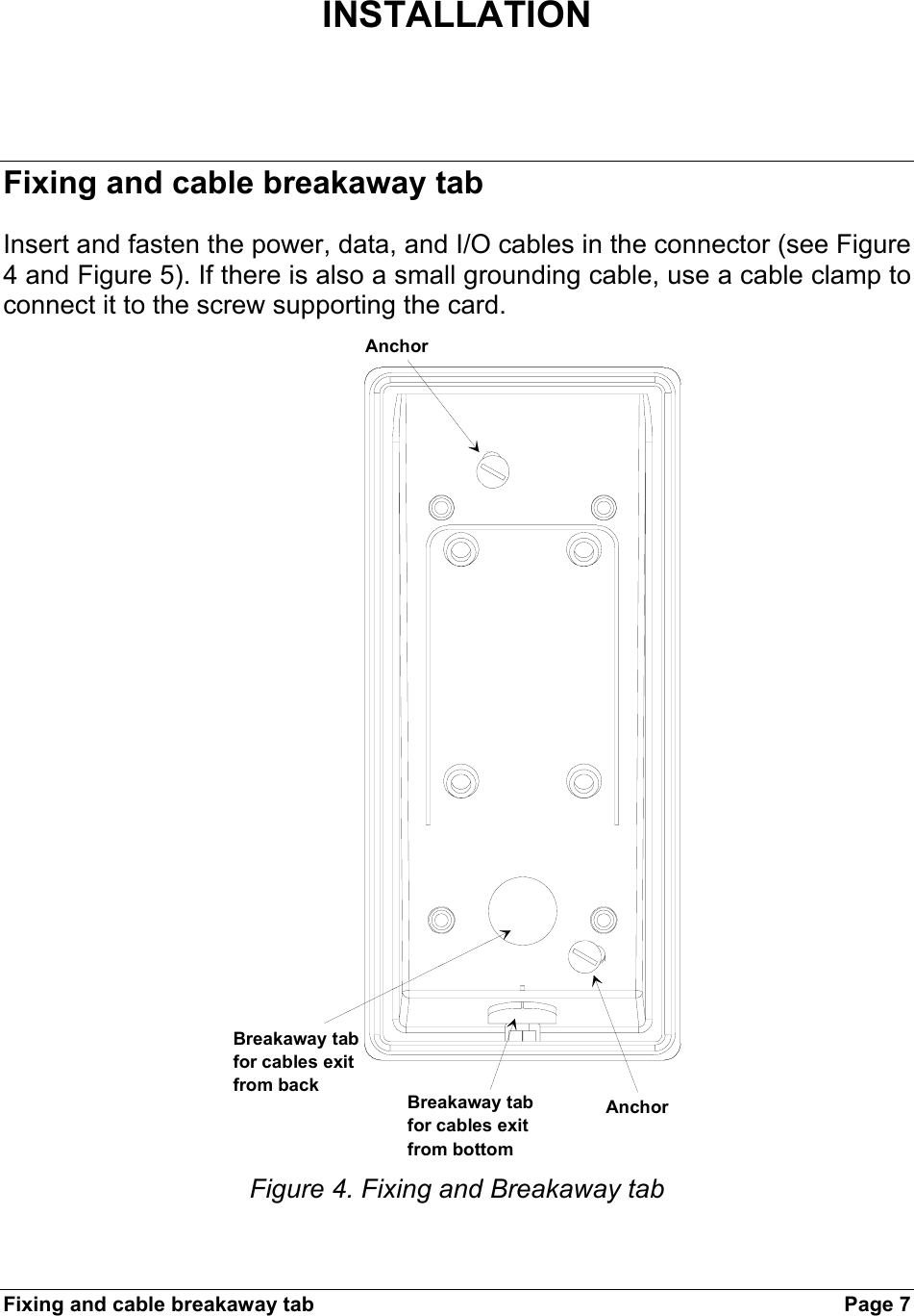
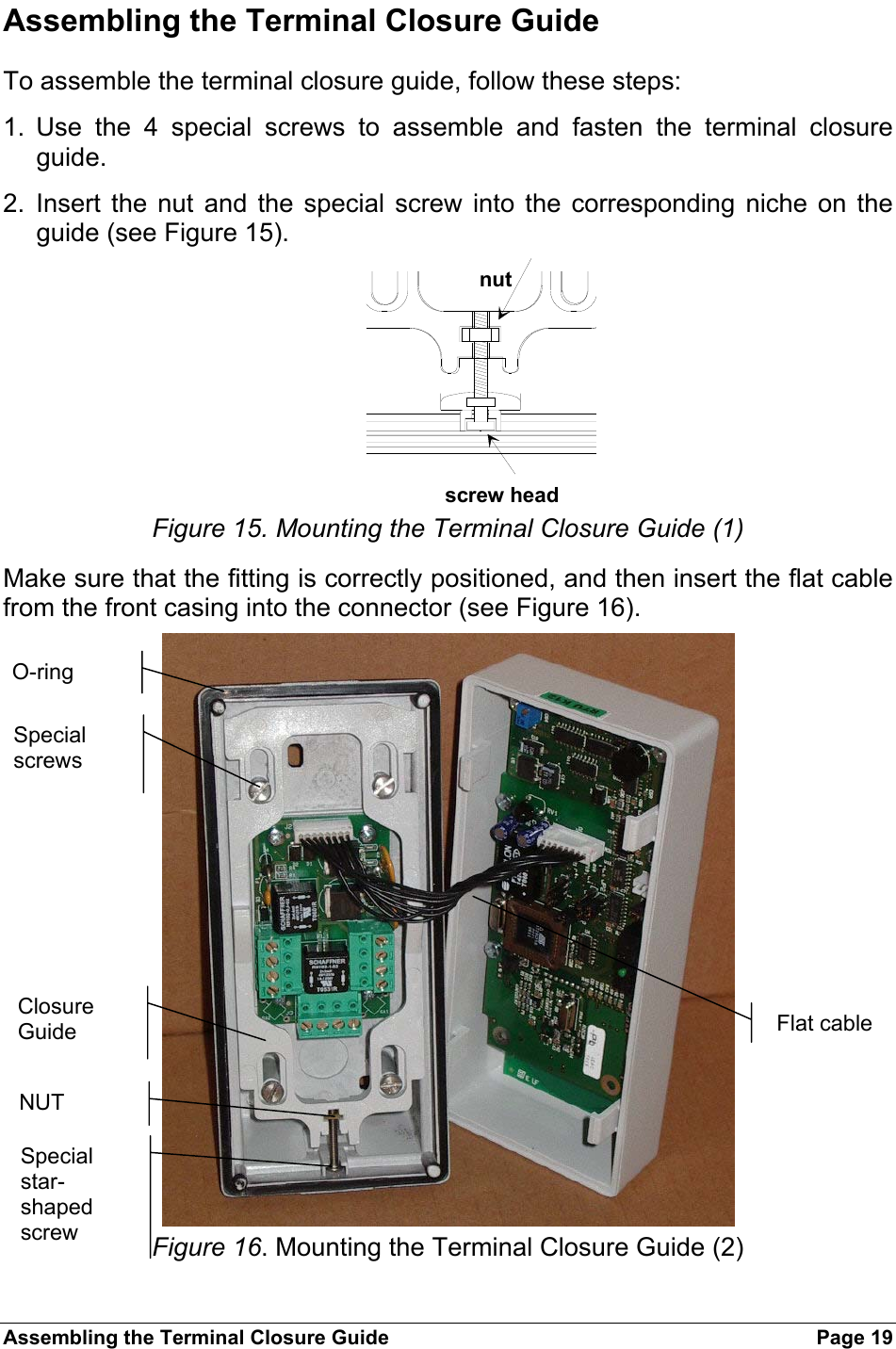
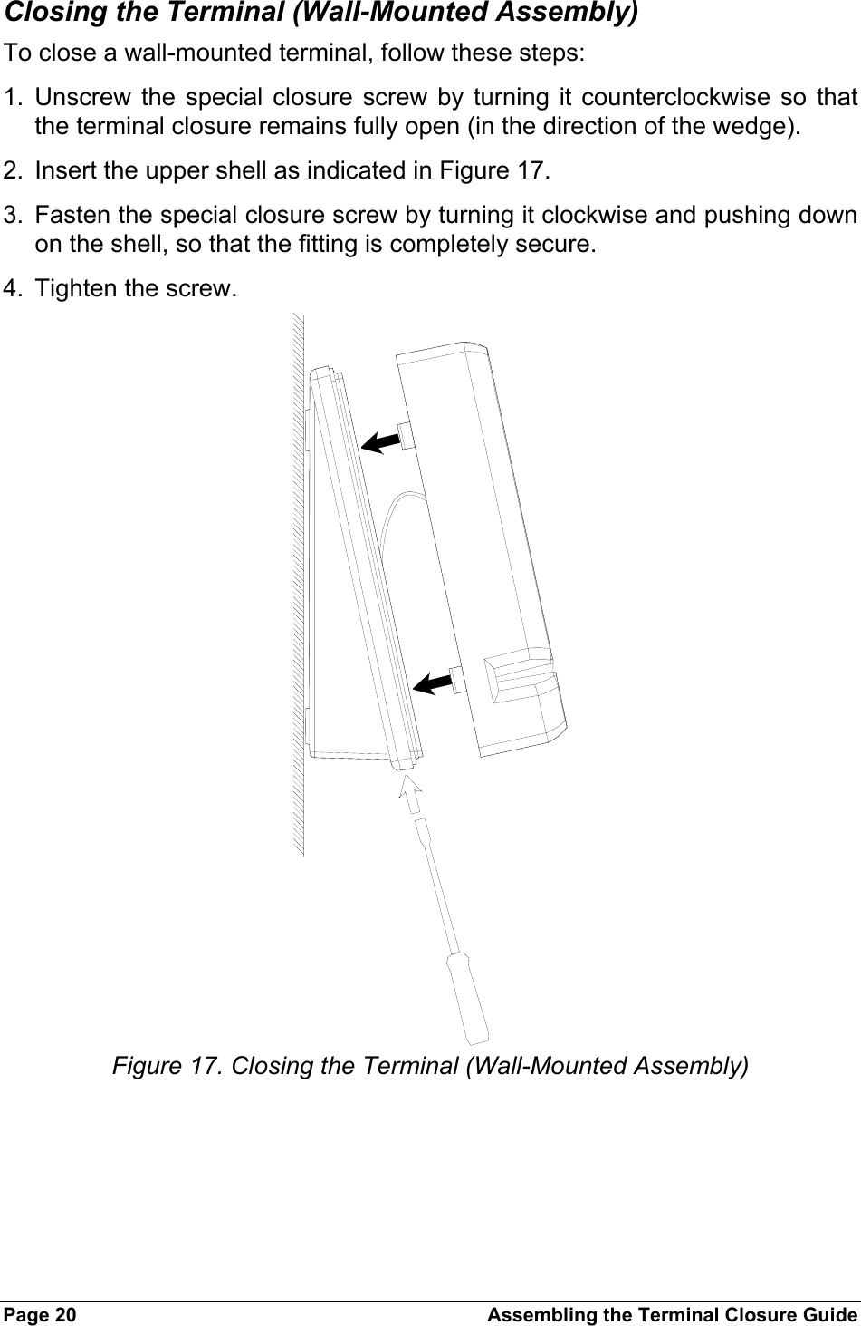
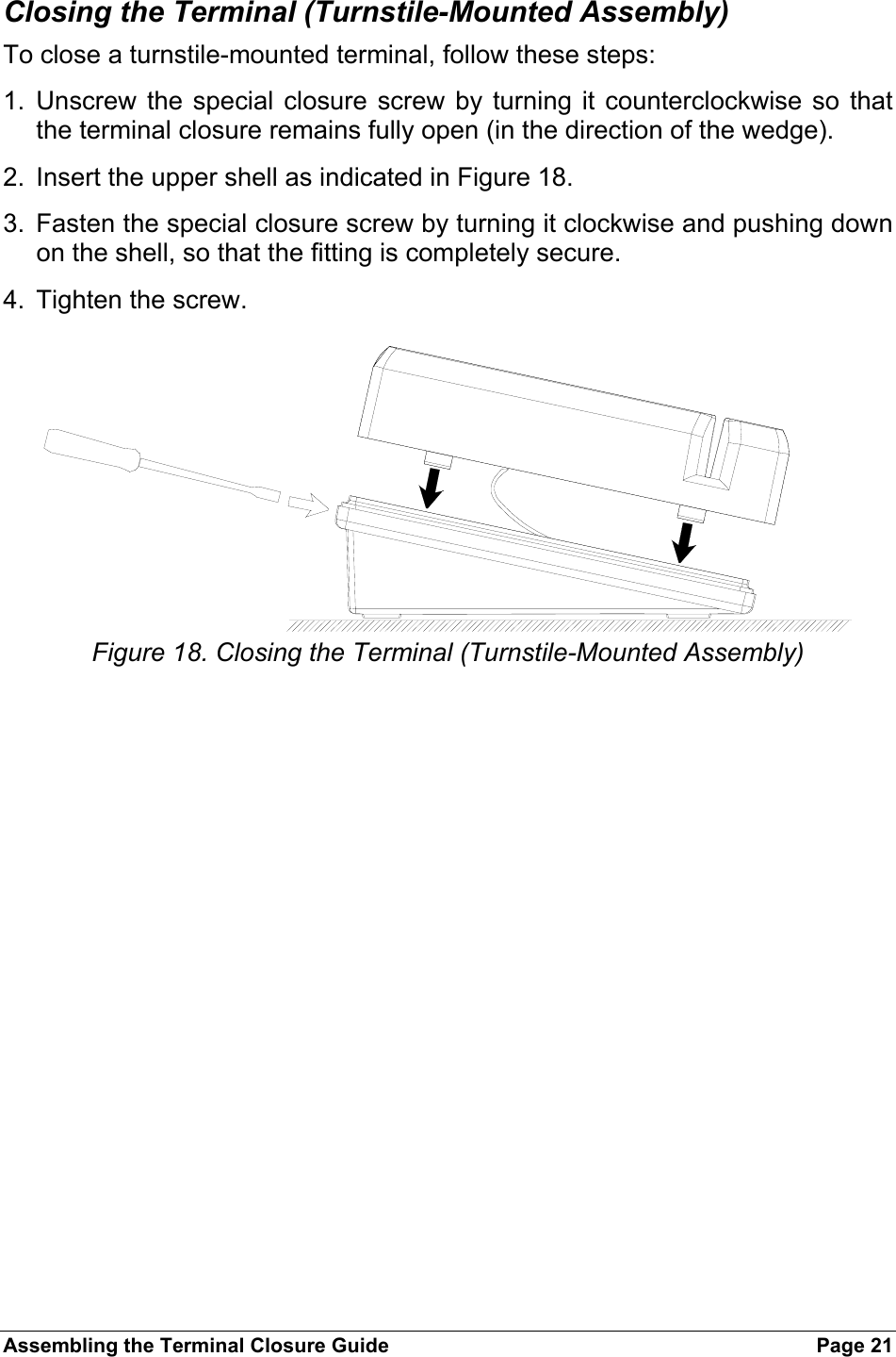
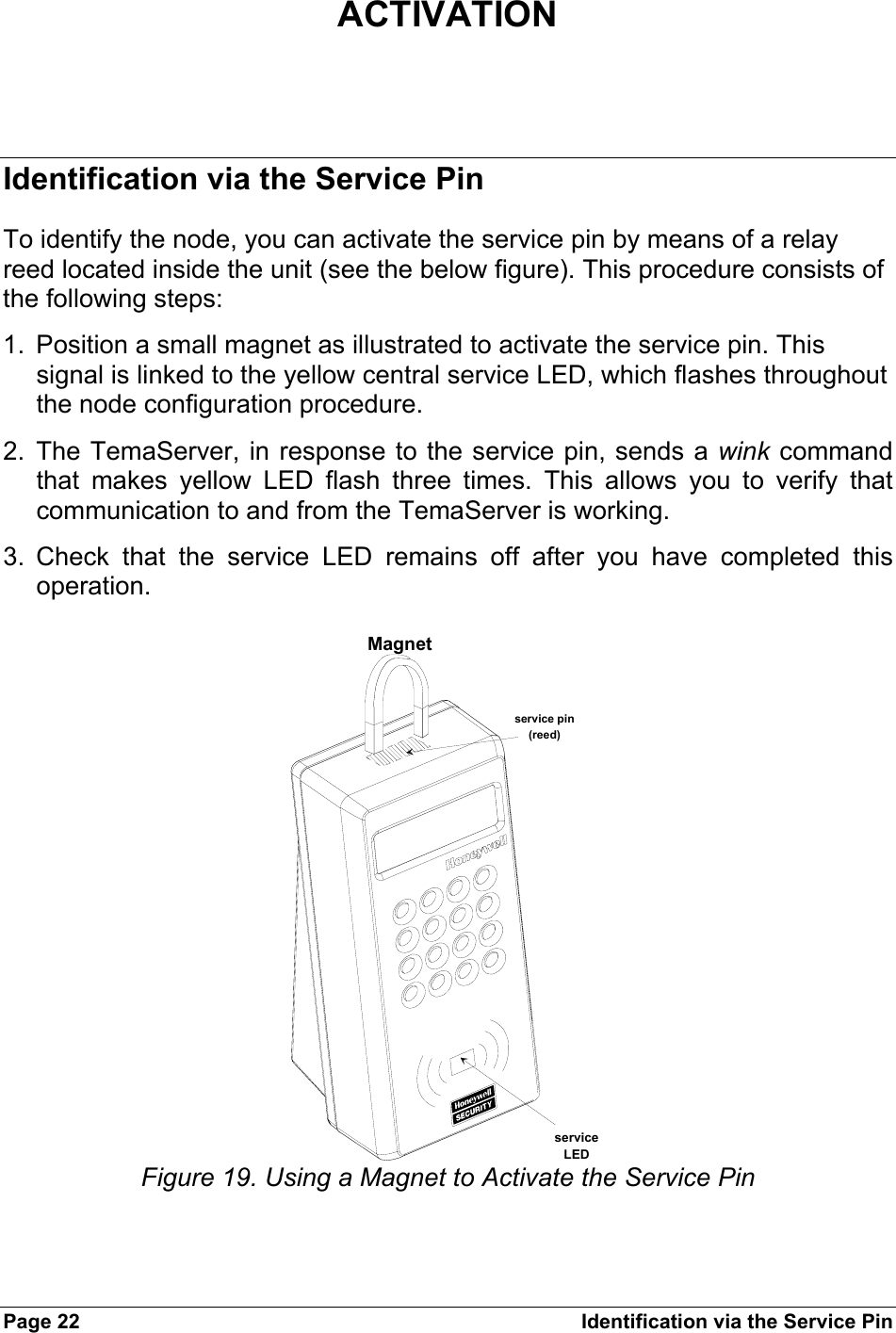
![Power Page 9 Power The RTU is powered at low voltage (12VDC 150mA) by a battery-operated power supply module (RTU-Qxx). In order to determine the correct size for power cables, refer to the table below. Max voltage cable drop = 1,0VDC for assure that in battery power working, when battery min voltage is 10,5V the min RTU power supply Î 9,5V (min RTU voltage). Type of cable Length (m) in relation to effective loadAWG mm2 ohm/Km 150 [mA] 300 [mA] 600 [mA] 1,2 [A] 2,4 [A]12 3,3 5,7 585 292 117 58 2914 2 8,8 379 189 76 38 19161,31423811948241218 0,9 21 159 79 32 16 8200,63498492010 522 0,35 52 64 32 13 6 3240,2853920842 +12V Ground When the cables go out-of-doors is mandatory to use shielded cables. The cables’ shielding must be connected to the ground connector. For internal wiring without shielded cables is recommended an electrical environment where the cables are well separated, even at short runs, especially to the power cables or external cables which can be essentially subjected to interference or lighting.](https://usermanual.wiki/Ademco/RTU-K12/User-Guide-737434-Page-9.png)
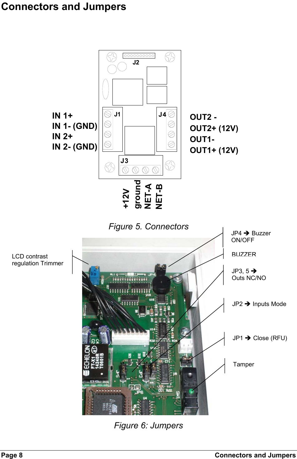
![NET Page 11 • Check that the length of the LONWORKS data cable corresponds to the norms indicated in Table 1. Type of cable Length [m] in relation to cable capacity AWG mm2 Ohm/Km 50nF/Km 100nF/Km 200nF/Km 500nF/Km 1uF/Km 12 3,3 5,7 2676 1892 1338 846 598 14 2 8,8 2153 1523 1077 681 482 16 1,3 14 1707 1207 854 540 382 18 0,9 21 1394 986 697 441 312 20 0,6 34 1096 775 548 346 245 22 0,35 52 886 626 443 280 198 24 0,2 85 693 490 346 219 155 Table 1. Length/Capacity of LONWORKS Data Cables (m) • The FTT10A Echelon v1.2 User Guide recommends the cables indicated in Table 2. Producer and Model AWG Connection to bus -maximum total length [m] Connection in free topology –maximum node-node length max. [m] Connection in free topology –maximum total wire length. [m] Belden 85102 16 2700 500 500 Belden 8471 16 2700 400 500 Level IV (twisted-pair, typically solid and unshielded) 22 1400 400 500 JY (St) 2x2x0.8 (4-wire helical twist, solid shielded) 20 900 320 500 TIA Cat5 / 900 250 450 Table 2. Recommended LONWORKS Cables](https://usermanual.wiki/Ademco/RTU-K12/User-Guide-737434-Page-11.png)
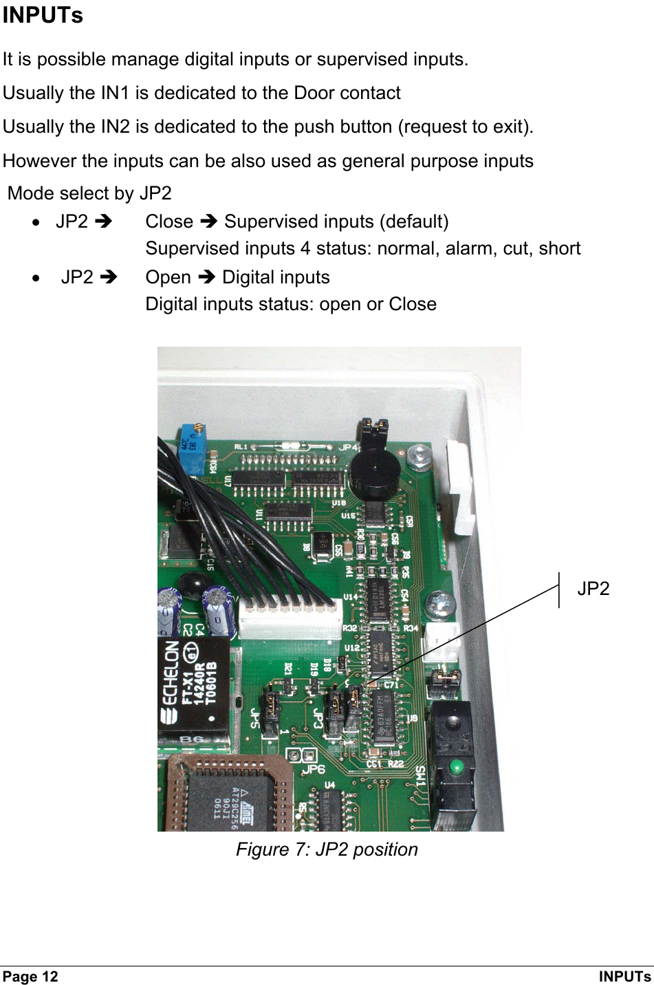
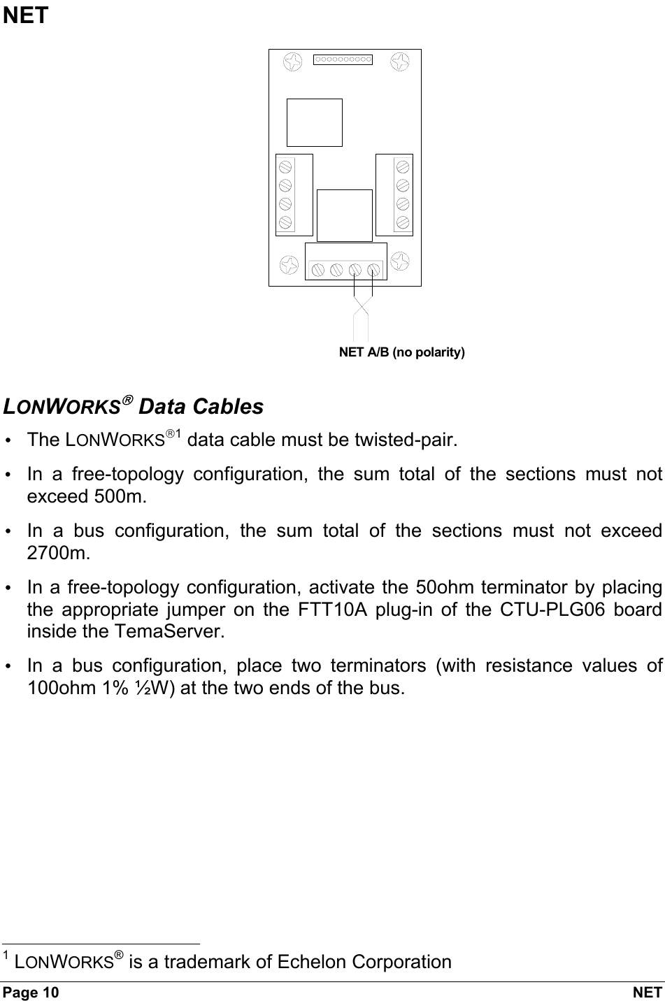
![INPUTs Page 13 Digital INPUTs The typical connection for digital dry contacts is shown in the next figure. input 1+input 1-input 2+input 2-Normally closed (door)Push Button+12V GroundDry contactNormally open (Exit)Figure 8. Clean Contacts Connection Example When the cables go out-of-doors it is mandatory to use shielded cables. The cables’ shielding must be connected to the ground connector. For internal wiring without shielded cables is recommended an electrical environment where the cables are well separated, even at short runs, especially to the power cables or external cables which can be essentially subjected to interference or lighting. Use a twisted-pair cable for the contact cables. Make sure that the cables correspond in size to the norms indicated in. Max resistance = 25 Ohm AWG mm2 ohm/Km [m]22 0,35 52 24024 0,2 85 147 Table 3. Length of Contact Cables](https://usermanual.wiki/Ademco/RTU-K12/User-Guide-737434-Page-13.png)
![Page 14 INPUTs Supervised INPUTs The typical connection for supervised dry contacts is shown in the next figure. Put the resistors close to the dry contact input 1+input 1-input 2+input 2-Normally closedDoorPush Button+12VGroundDry contactsNormally open (Exit)yellowyellowWhiteWhiteFigure 9. Supervised input connection Yellow resistor: 1210 Ohm 1% White resistor: 392 Ohm 1% Close contact resistance: 296 Ohm Open contact resistance: 1210 Ohm When the cables go out-of-doors is mandatory to use shielded cables. The cables’ shielding must be connected to the ground connector. For internal wiring without shielded cables it is recommended an electrical environment where the cables are well separated, even at short runs, especially to the power cables or external cables which can be essentially subjected to interference or lighting. Use a twisted-pair cable for the contact cables. Make sure that the cables correspond in size to the norms indicated in. Max resistance = 25 Ohm AWG mm2 ohm/Km [m]22 0,35 52 24024 0,2 85 147 Table 4. Length of Contact Cables](https://usermanual.wiki/Ademco/RTU-K12/User-Guide-737434-Page-14.png)
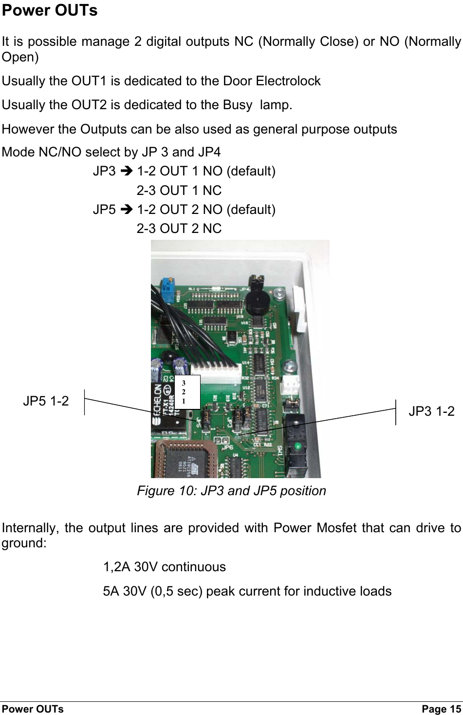
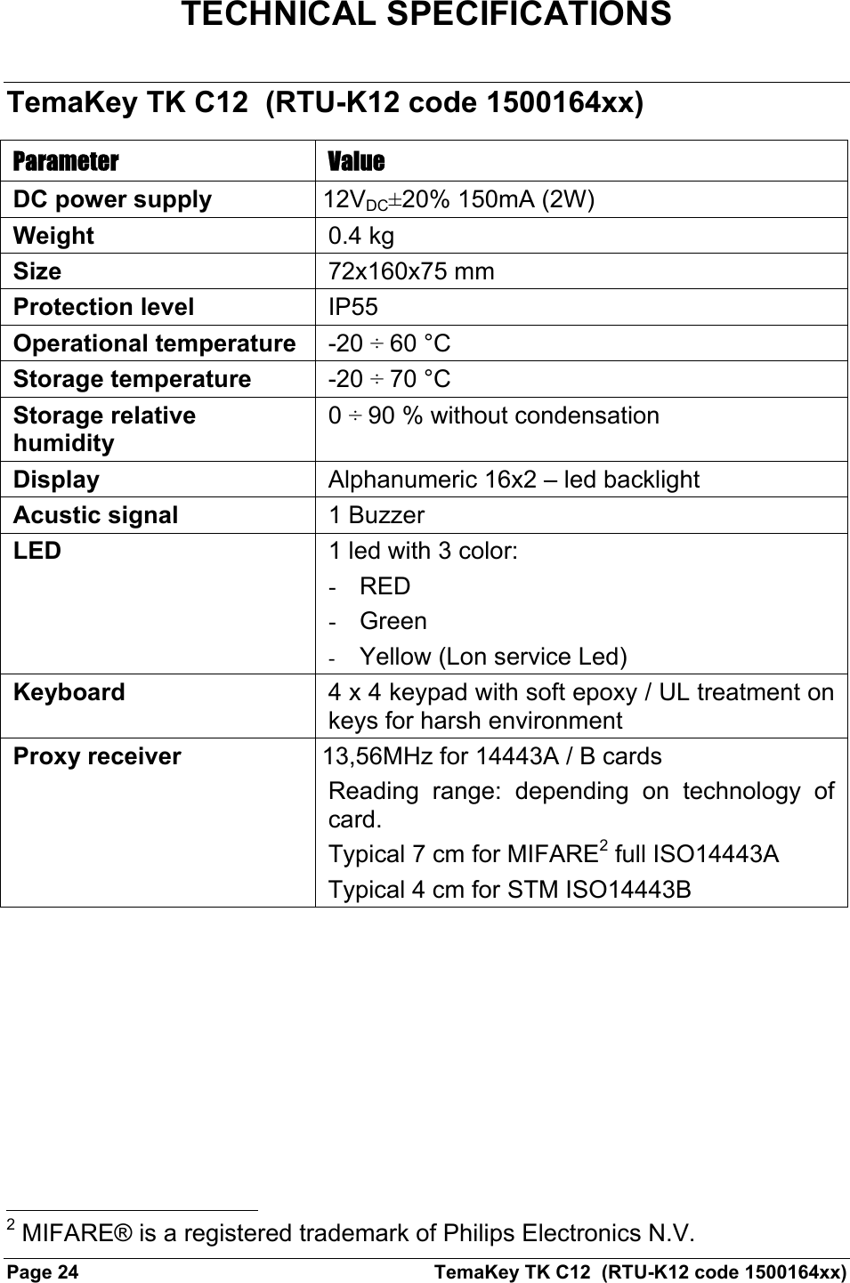
![TemaKey TK C12 (RTU-K12 code 1500164xx) Page 25 Inputs 2 supervised or digital inputs. Mode select by JP2 JP2 = Close Î Supervised inputs JP2 = Open Î Digital inputs • Supervised inputs with 4 status: normal, alarm, cut, short • Digital inputs with status: open or Close Current 0 to 10mA for each input (internal reference 5Vdc) Voltage +14V max. 0V min Outputs Number 2 Type Power Open drain (MOSFET) Current 1,2A continuous 5A (0,5sec) impulsive Voltage 10V...+14V (internal Power supply) Voltage (absolute max) 10V...+30V (from external Power supply). Current 1,2A [5A / 0,5sec peak max – inductive load] Normality NO or NC via Jumper setting JP3 = 1-2 OUT 1 NO 2-3 OUT 1 NC JP5 = 1-2 OUT 2 NO 2-3 OUT 2 NC Wire length connection: it depends on cable diameter, load current sink and load min power supply On state resistance = typical 20 mOhm Load 1A = 0.02 V](https://usermanual.wiki/Ademco/RTU-K12/User-Guide-737434-Page-25.png)