Ademco RTU-K12 RFID Access Control User Manual 737434
Honeywell International Inc RFID Access Control 737434
Ademco >
User manual
TK C12 (RTUK12)
WEEE/ RoHS Compliant
Directive 2002/95/EC
Installation Manual ver.1.1

Page 2 FCC NOTICE
TABLE OF CONTENTS
FCC NOTICE .............................................................................................. 3
Canadian Compliance Statement ........................................................ 3
Mounting Instructions .................................................................................. 4
Attaching the Terminal Support Plate.......................................................... 5
Channeling the Cables from the Bottom of the Box ............................. 6
Fixing and cable breakaway tab.................................................................. 7
Connectors and Jumpers ............................................................................ 8
Power .......................................................................................................... 9
NET ........................................................................................................... 10
LONWORKS Data Cables................................................................ 10
INPUTs...................................................................................................... 12
Digital INPUTs.................................................................................... 13
Supervised INPUTs............................................................................ 14
Power OUTs.............................................................................................. 15
Resistive load..................................................................................... 16
Inductive load..................................................................................... 16
Inductive load with external Power supply ......................................... 17
External relays ................................................................................... 18
Assembling the Terminal Closure Guide................................................... 19
Closing the Terminal (Wall-Mounted Assembly) ................................ 20
Closing the Terminal (Turnstile-Mounted Assembly) ......................... 21
Identification via the Service Pin ............................................................... 22
Identification via Bar Code ........................................................................ 23
TemaKey TK C12 (RTU-K12 code 1500164xx) ....................................... 24
Optional Parts .................................................................................... 26
Recycling................................................................................................... 27

FCC NOTICE Page 3
FCC NOTICE
NOTE: This equipment has been tested and found to comply with the limits
for a Class B digital device, pursuant to Part 15 of FCC Rules. These limits
are designed to provide reasonable protection against harmful interference in
a residential installation. This equipment generates, uses and can radiate
radio frequency energy and, if not installed and used in accordance with the
instructions, may cause harmful interference to radio communications.
However, these is no guarantee that interference will not occur in a particular
installation.
If this equipment does cause harmful interference to radio or television
reception, which can be determined by tuning the equipment off and on, the
user is encouraged to try to correct the interference by one or more the
following measures:
-- Reorient or relocate the receiving antenna.
-- Increase the separation between the equipment and receiver.
-- Connect the equipment into an outlet on a circuit different from that to
which the receiver is connected.
-- Consult the dealer or an experienced radio/TV technician for help.
Caution: any modification or change not expressly approved by the party
responsible for compliance could void the user’s authority to operate the
equipment.
Canadian Compliance Statement
This Class B Digital apparatus meets all the requirements of the Canadian
Interference-Causing Equipment Regulations.
Cet appareil numerique de la classe B respecte les exigences du Reglement
sur le material broilleur du Canada.
This device co m plies w ith Part 15 of the FCC Rules.
Operation is subjec t to the following two conditions:
(1) this device may not cause harmful interference, and
(2) this device must accept any interference received,
including interference that m ay cause undesired op eration.
FCC ID: HS9-RTU-K12
Page 4 Mounting Instructions
PRELIMINARY OPERATIONS
Mounting Instructions
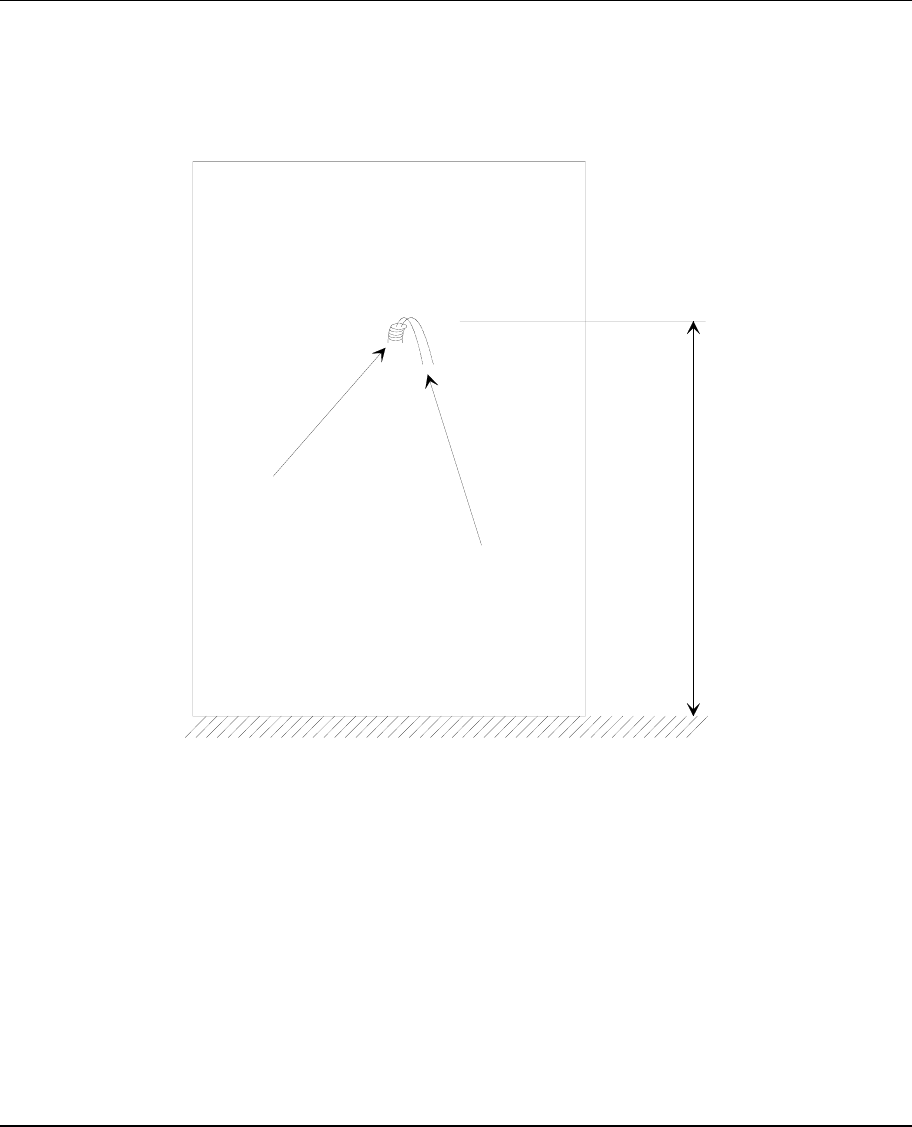
The cables are attached to an encased box. Make sure that you place the
box at a height of 120cm from the floor (see Figure 1).
tube
cables
120 cm
floor
Figure 1. Space Requirements for Mounting
Attaching the Terminal Support Plate Page 5
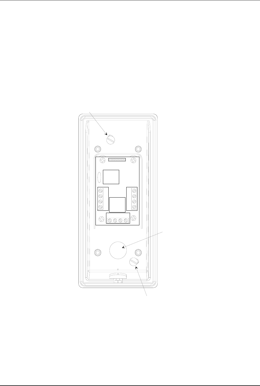
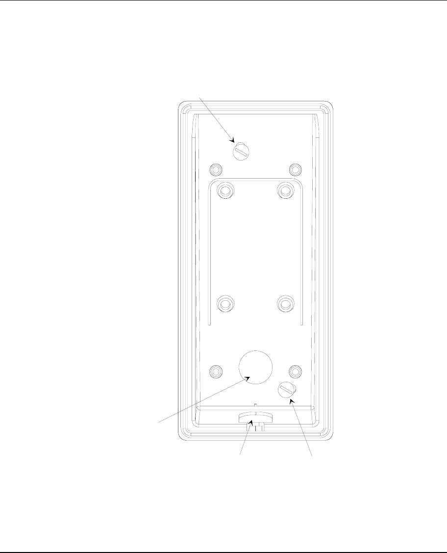
Attaching the Terminal Support Plate
To attach the terminal support plate, follow these steps:
1. Drill two holes into the wall to accommodate the plastic anchors that hold
up the support plate (you must use M4 screws).
2. Make sure that the box attached to the wall is aligned with the niche on the
lower part of the support plate
3. Use a ∅ 4mm slotted screwdriver.
A
nchor
A
nchor
Cables
entrance
Figure 2. Attaching the Support Plate
Page 6 Attaching the Terminal Support Plate
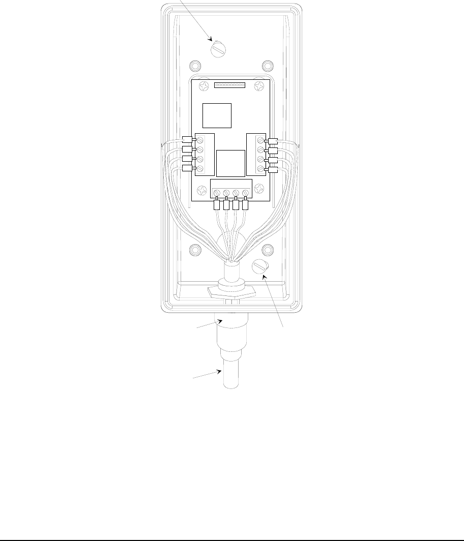
Channeling the Cables from the Bottom of the Box
As an alternative, you can channel the cables so that they issue from the
bottom of the box (see Figure 3). This alternative procedure consists of the
following steps:
1. Drill a hole in the breakaway tab and apply a cable clamp with a clutch for
the cable tube.
2. Remove the cable clamps from the rear side and apply the stopper.
Anchor
Anchor
PG9 cable
clamp
Multi-pole
cable
(15 poles)
Figure 3. Channeling the Cables from the Bottom of the Box
Fixing and cable breakaway tab Page 7
INSTALLATION
Fixing and cable breakaway tab
Insert and fasten the power, data, and I/O cables in the connector (see Figure
4 and Figure 5). If there is also a small grounding cable, use a cable clamp to
connect it to the screw supporting the card.
Anchor
Anchor
Breakaway tab
for cables exit
from bottom
Breakaway tab
for cables exit
from back
Figure 4. Fixing and Breakaway tab
Page 8 Connectors and Jumpers
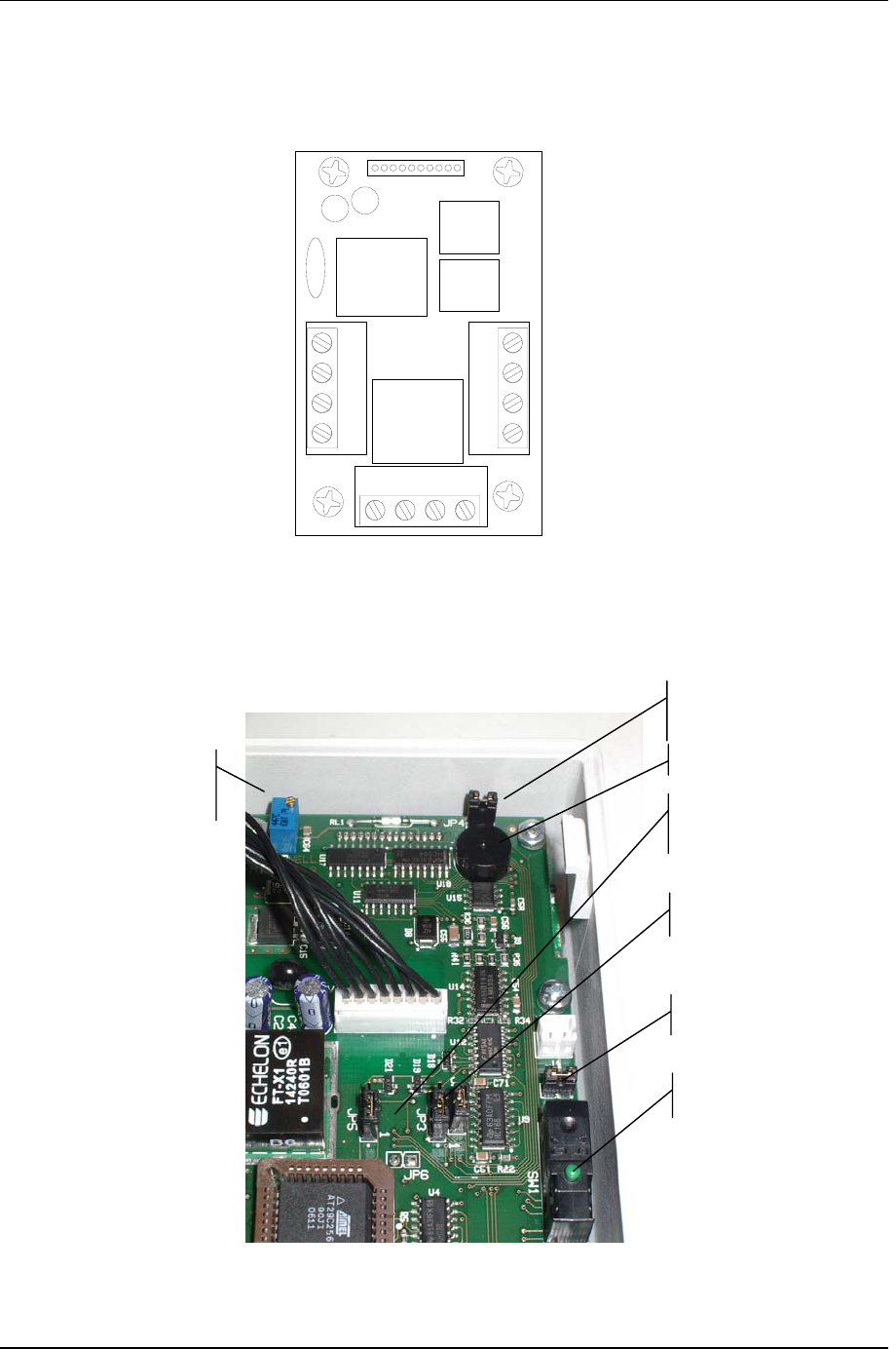
Connectors and Jumpers
OUT2 -
OUT2+ (12V)
OUT1-
OUT1+ (12V)
IN 1+
IN 1- (GND)
IN 2+
IN 2- (GND)
+12V
ground
NET-A
NET-B
J1
J3
J4
J2
Figure 5. Connectors
Figure 6: Jumpers
JP4 Î Buzzer
ON/OFF
JP1 Î Close (RFU)
JP2 Î Inputs Mode
JP3, 5 Î
Outs NC/NO
LCD contrast
regulation Trimmer
BUZZER
Tamper
Power Page 9
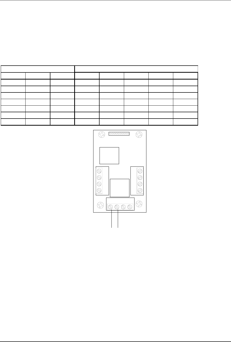
Power
The RTU is powered at low voltage (12VDC 150mA) by a battery-operated
power supply module (RTU-Qxx). In order to determine the correct size for
power cables, refer to the table below. Max voltage cable drop = 1,0VDC for
assure that in battery power working, when battery min voltage is 10,5V the
min RTU power supply Î 9,5V (min RTU voltage).
Type of cable Length (m) in relation to effective load
AWG mm2 ohm/Km 150 [mA] 300 [mA] 600 [mA] 1,2 [A] 2,4 [A]
12 3,3 5,7 585 292 117 58 29
14 2 8,8 379 189 76 38 19
161,314238119482412
18 0,9 21 159 79 32 16 8
200,63498492010 5
22 0,35 52 64 32 13 6 3
240,2853920842
+12V Ground
When the cables go out-of-doors is mandatory to use shielded cables. The
cables’ shielding must be connected to the ground connector.
For internal wiring without shielded cables is recommended an electrical
environment where the cables are well separated, even at short runs,
especially to the power cables or external cables which can be essentially
subjected to interference or lighting.
Page 10 NET
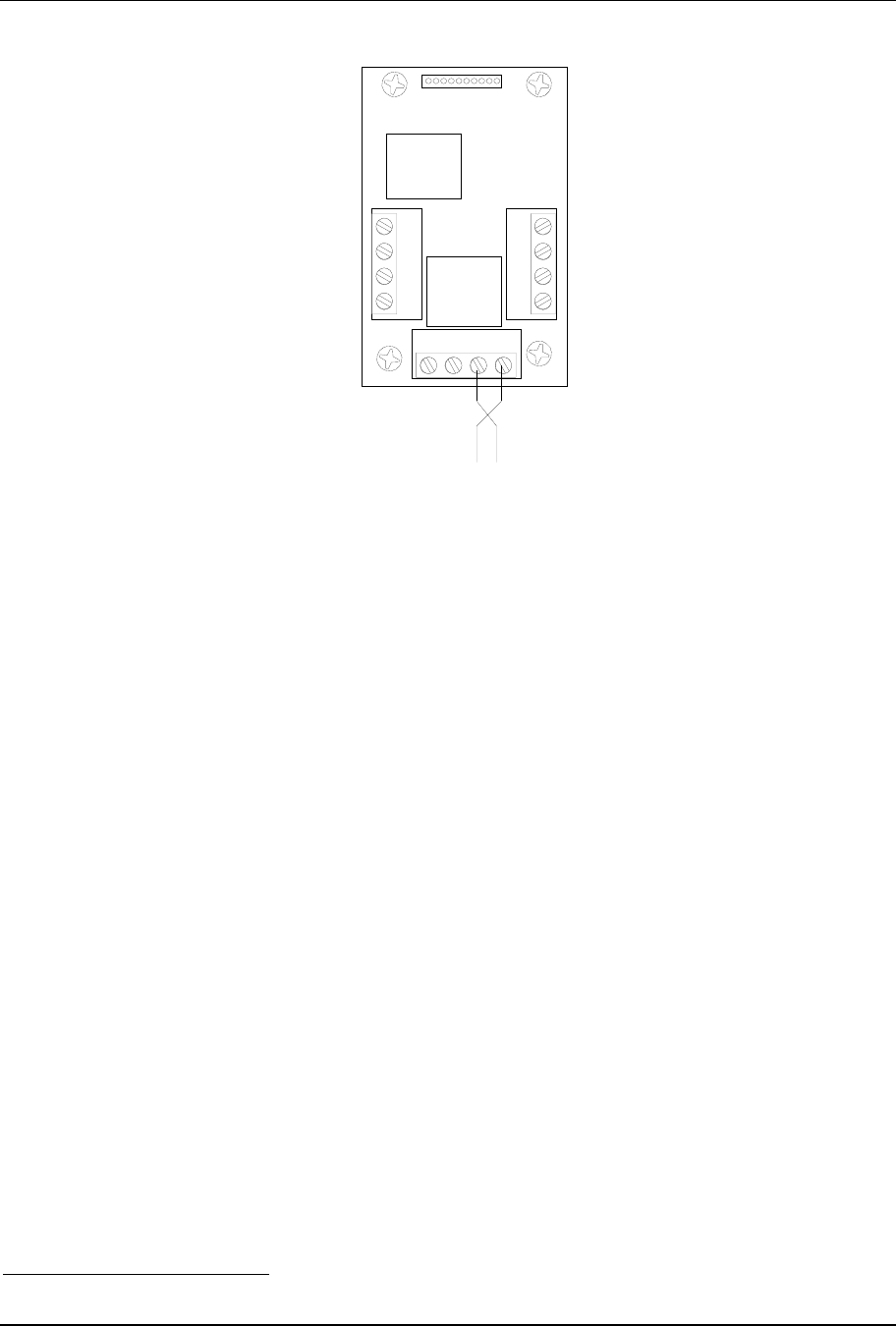
NET
NET A/B (no polarity)
LONWORKS
Data Cables
• The LONWORKS1 data cable must be twisted-pair.
• In a free-topology configuration, the sum total of the sections must not
exceed 500m.
• In a bus configuration, the sum total of the sections must not exceed
2700m.
• In a free-topology configuration, activate the 50ohm terminator by placing
the appropriate jumper on the FTT10A plug-in of the CTU-PLG06 board
inside the TemaServer.
• In a bus configuration, place two terminators (with resistance values of
100ohm 1% ½W) at the two ends of the bus.
1 LONWORKS® is a trademark of Echelon Corporation

NET Page 11
• Check that the length of the LONWORKS data cable corresponds to the
norms indicated in Table 1.
Type of cable Length [m] in relation to cable capacity
AWG mm2 Ohm/Km 50nF/Km 100nF/Km 200nF/Km 500nF/Km 1uF/Km
12 3,3 5,7 2676 1892 1338 846 598
14 2 8,8 2153 1523 1077 681 482
16 1,3 14 1707 1207 854 540 382
18 0,9 21 1394 986 697 441 312
20 0,6 34 1096 775 548 346 245
22 0,35 52 886 626 443 280 198
24 0,2 85 693 490 346 219 155
Table 1. Length/Capacity of LONWORKS
Data Cables (m)
• The FTT10A Echelon v1.2 User Guide recommends the cables indicated
in Table 2.
Producer and Model AWG Connection to
bus -maximum
total length [m]
Connection in free
topology –maximum
node-node length
max. [m]
Connection in free
topology –maximum
total wire length. [m]
Belden 85102 16 2700 500 500
Belden 8471 16 2700 400 500
Level IV (twisted-pair,
typically solid and
unshielded)
22 1400 400 500
JY (St) 2x2x0.8 (4-wire
helical twist, solid
shielded)
20 900 320 500
TIA Cat5 / 900 250 450
Table 2. Recommended LONWORKS
Cables
Page 12 INPUTs
INPUTs
It is possible manage digital inputs or supervised inputs.
Usually the IN1 is dedicated to the Door contact
Usually the IN2 is dedicated to the push button (request to exit).
However the inputs can be also used as general purpose inputs
Mode select by JP2
• JP2 Î Close Î Supervised inputs (default)
Supervised inputs 4 status: normal, alarm, cut, short
• JP2 Î Open Î Digital inputs
Digital inputs status: open or Close
Figure 7: JP2 position
JP2
INPUTs Page 13
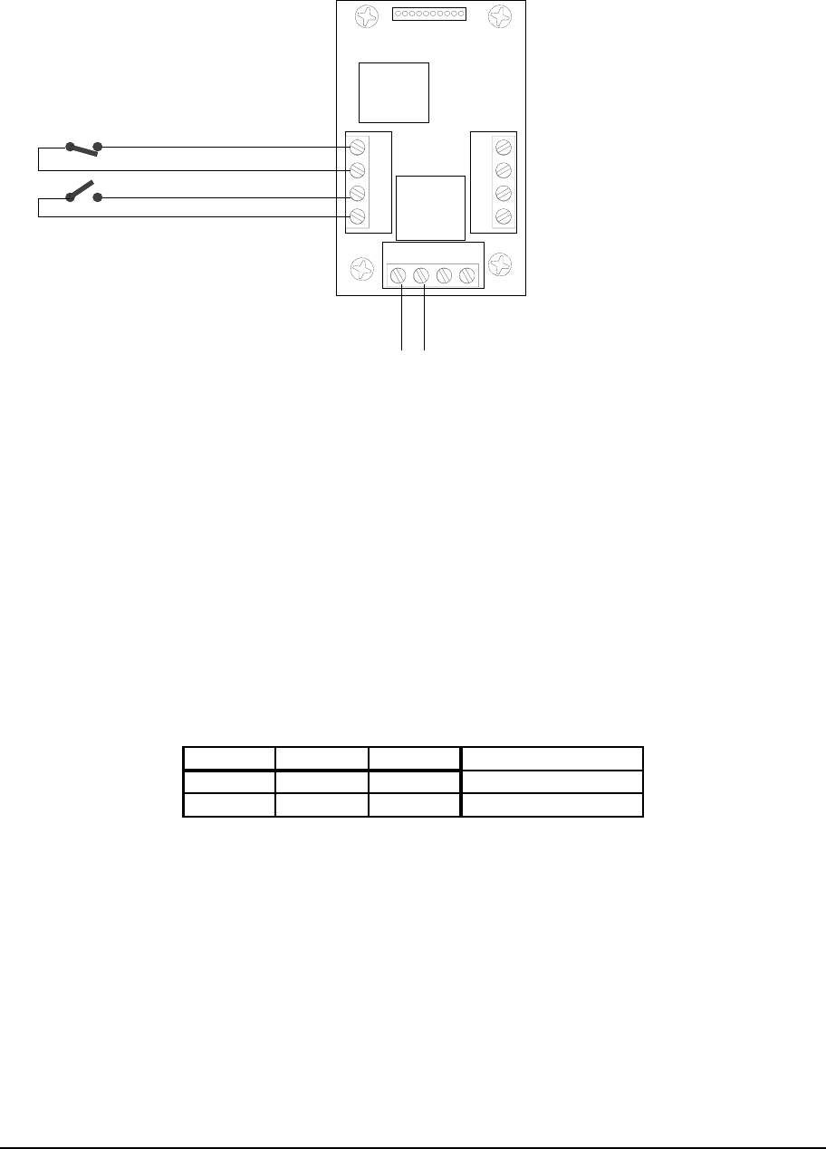
Digital INPUTs
The typical connection for digital dry contacts is shown in the next figure.
input 1+
input 1-
input 2+
input 2-
Normally closed (door)
Push Button
+12V Ground
Dry contact
Normally open (Exit)
Figure 8. Clean Contacts Connection Example
When the cables go out-of-doors it is mandatory to use shielded cables. The
cables’ shielding must be connected to the ground connector.
For internal wiring without shielded cables is recommended an electrical
environment where the cables are well separated, even at short runs,
especially to the power cables or external cables which can be essentially
subjected to interference or lighting.
Use a twisted-pair cable for the contact cables. Make sure that the cables
correspond in size to the norms indicated in.
Max resistance = 25 Ohm
A
WG mm2 ohm/Km [m]
22 0,35 52 240
24 0,2 85 147
Table 3. Length of Contact Cables
Page 14 INPUTs
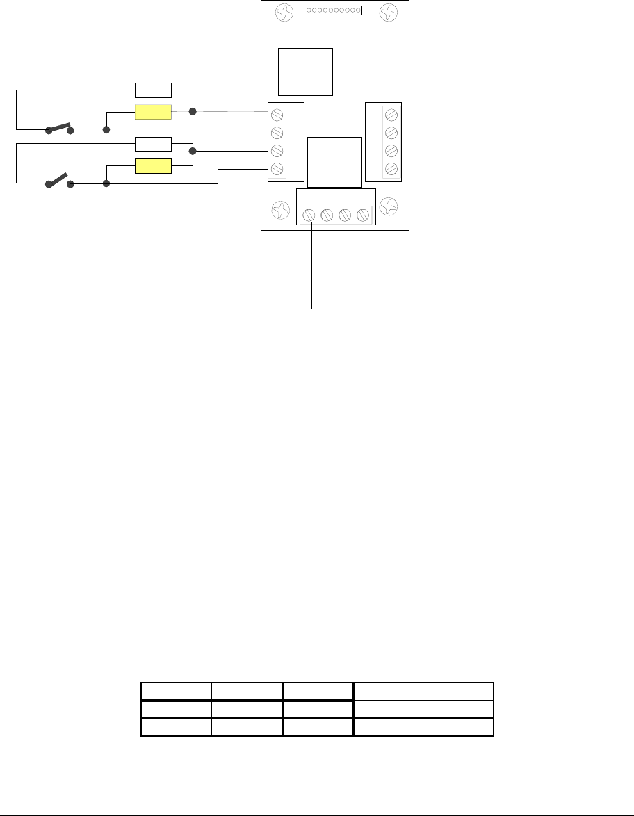
Supervised INPUTs
The typical connection for supervised dry contacts is shown in the next figure.
Put the resistors close to the dry contact
input 1+
input 1-
input 2+
input 2-
Normally closed
Door
Push Button
+12V
Ground
Dry contacts
Normally open (Exit)
yellow
yellow
White
White
Figure 9. Supervised input connection
Yellow resistor: 1210 Ohm 1%
White resistor: 392 Ohm 1%
Close contact resistance: 296 Ohm
Open contact resistance: 1210 Ohm
When the cables go out-of-doors is mandatory to use shielded cables. The
cables’ shielding must be connected to the ground connector.
For internal wiring without shielded cables it is recommended an electrical
environment where the cables are well separated, even at short runs,
especially to the power cables or external cables which can be essentially
subjected to interference or lighting.
Use a twisted-pair cable for the contact cables. Make sure that the cables
correspond in size to the norms indicated in.
Max resistance = 25 Ohm
A
WG mm2 ohm/Km [m]
22 0,35 52 240
24 0,2 85 147
Table 4. Length of Contact Cables
Power OUTs Page 15
Power OUTs
It is possible manage 2 digital outputs NC (Normally Close) or NO (Normally
Open)
Usually the OUT1 is dedicated to the Door Electrolock
Usually the OUT2 is dedicated to the Busy lamp.
However the Outputs can be also used as general purpose outputs
Mode NC/NO select by JP 3 and JP4
JP3 Î 1-2 OUT 1 NO (default)
2-3 OUT 1 NC
JP5 Î 1-2 OUT 2 NO (default)
2-3 OUT 2 NC
Figure 10: JP3 and JP5 position
Internally, the output lines are provided with Power Mosfet that can drive to
ground:
1,2A 30V continuous
5A 30V (0,5 sec) peak current for inductive loads
JP3 1-2
JP5 1-2
3
2
1
Page 16 Power OUTs
When the cables go out-of-doors is mandatory to use shielded cables. The
cables’ shielding must be connected to the respective ground connectors
(GND).
For internal wiring without shielded cables is recommended an electrical
environment where the cables are well separated, even at short runs,
especially to the power cables or external cables which can be essentially
subjected to interference or lighting.
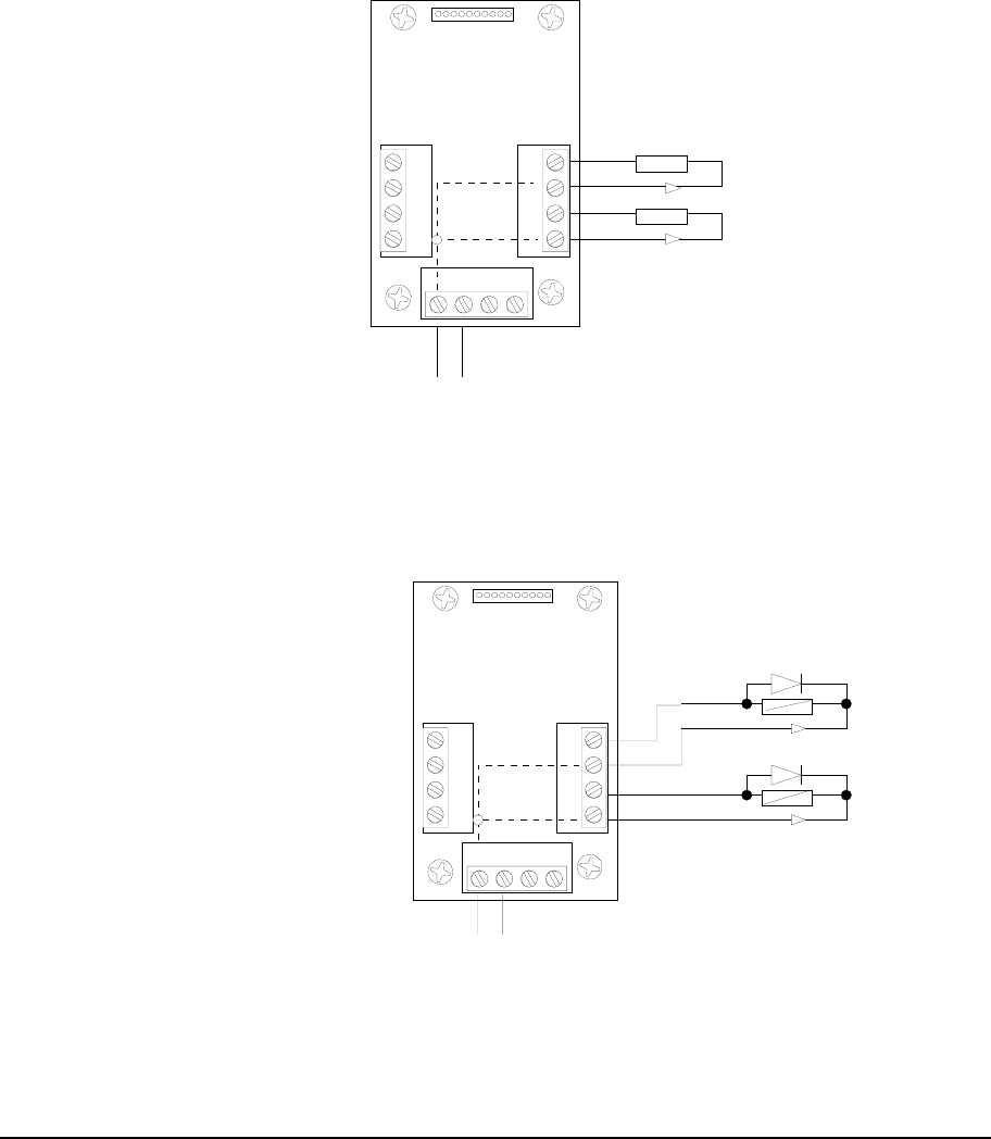
Resistive load
+12V
OUT1-
+12V
OUT2-
max 1,2A
max 1,2A
12VDC / GND
Figure 11: Connecting to resistive loads
Inductive load
+12V
OUT1-
max 1,2A (5A impulse)
1N4004
+12V
OUT2-
max 1,2A (5A impulse)
1N4004
12VDC / GND
Figure 12: Connecting to inductive loads
Power OUTs Page 17
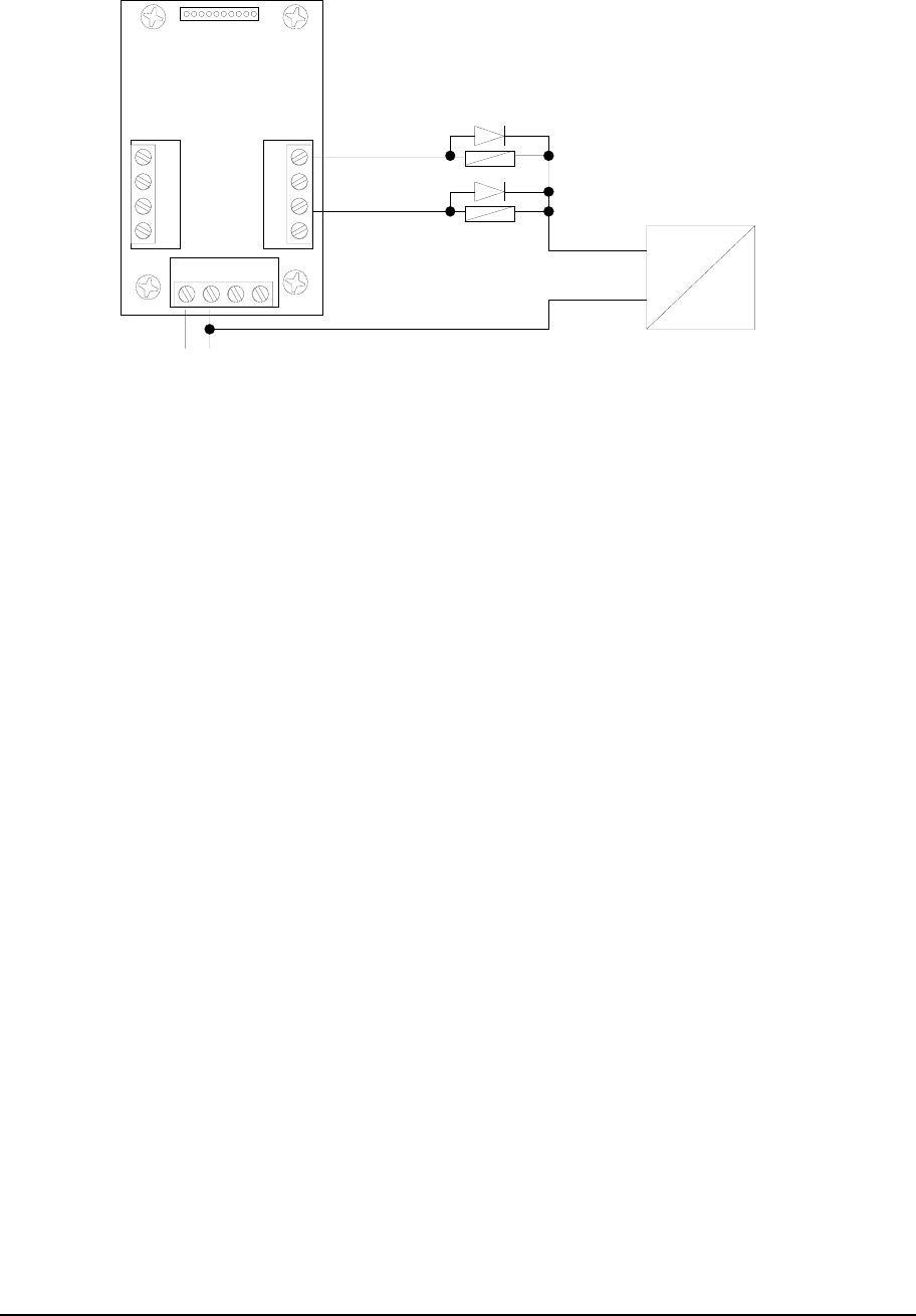
Inductive load with external Power supply
AC IN
DC OUT
OUT1-
max 1,2A (5A impulse)
1N4004
12VDC / GND
10 to 30VDC
OUT2-
1N4004
GND
Isolated Power Supply
Figure 13: Connecting to inductive loads with an external isolated power
supply
Note for inductive loads
• In this case is mandatory use the 1N4004 diodes as in figure. Two (2)
Diodes are included in the product
• The external power supply has to be isolated
Page 18 Power OUTs
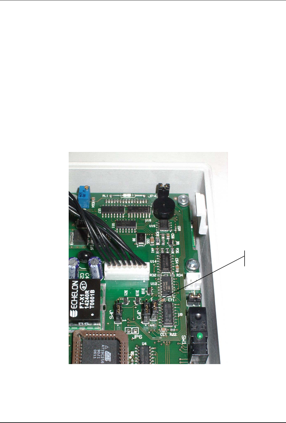
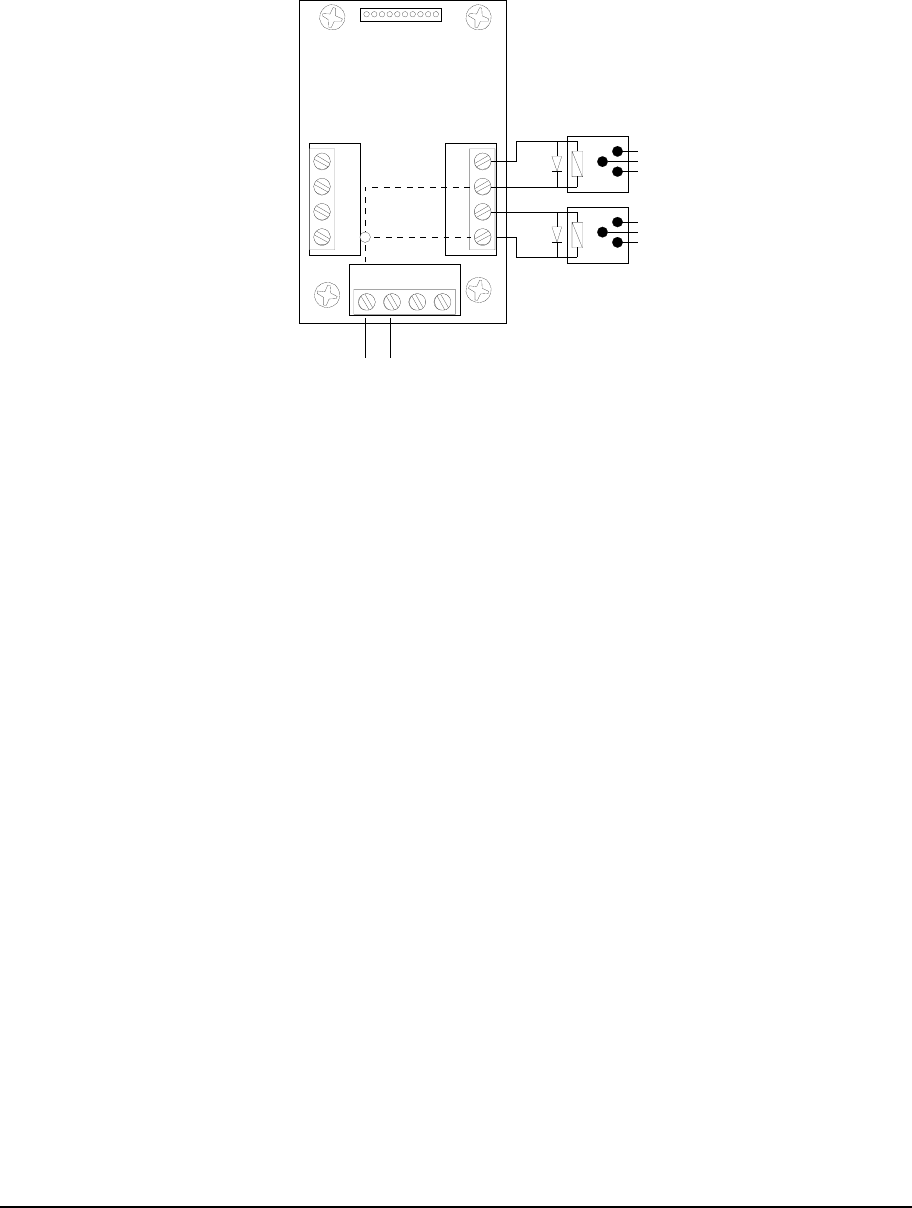
External relays
When the load exceeds the max internal Mosfet current it is possible to
use external relays
12VDC / GND
OUT1
OUT2
12V relay
12V relay
1N4004
1N4004
Figure 14. Relays OUT
Notes:
• Use 12VDC relay - max coil current = 100mA each.
In this case is mandatory use the 1N4004 diodes as in figure.
Assembling the Terminal Closure Guide Page 19
Assembling the Terminal Closure Guide
To assemble the terminal closure guide, follow these steps:
1. Use the 4 special screws to assemble and fasten the terminal closure
guide.
2. Insert the nut and the special screw into the corresponding niche on the
guide (see Figure 15).
nut
screw head
Figure 15. Mounting the Terminal Closure Guide (1)
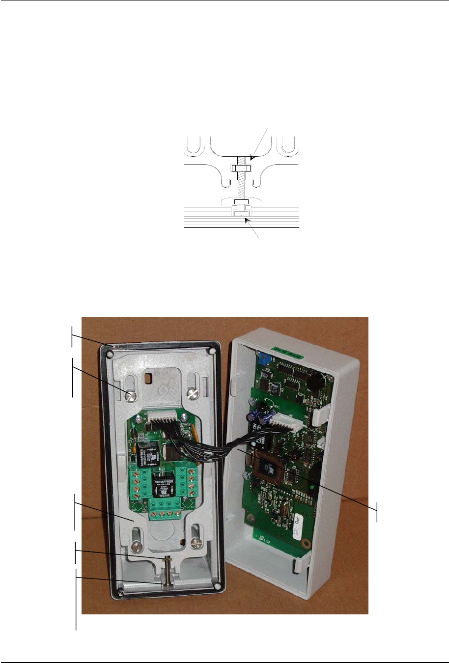
Make sure that the fitting is correctly positioned, and then insert the flat cable
from the front casing into the connector (see Figure 16).
Figure 16. Mounting the Terminal Closure Guide (2)
O-ring
Special
screws
Closure
Guide
NUT
Special
star-
shaped
screw
Flat cable
Page 20 Assembling the Terminal Closure Guide
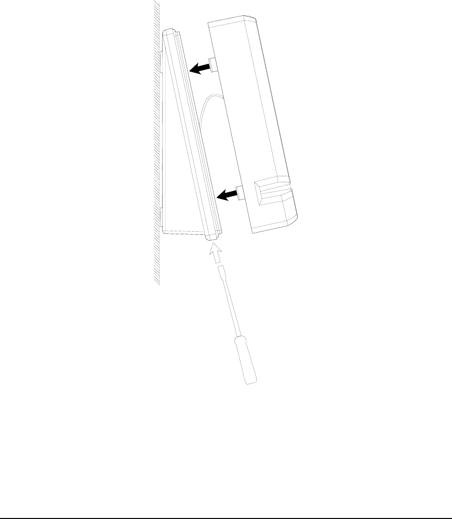
Closing the Terminal (Wall-Mounted Assembly)
To close a wall-mounted terminal, follow these steps:
1. Unscrew the special closure screw by turning it counterclockwise so that
the terminal closure remains fully open (in the direction of the wedge).
2. Insert the upper shell as indicated in Figure 17.
3. Fasten the special closure screw by turning it clockwise and pushing down
on the shell, so that the fitting is completely secure.
4. Tighten the screw.
Figure 17. Closing the Terminal (Wall-Mounted Assembly)
Assembling the Terminal Closure Guide Page 21
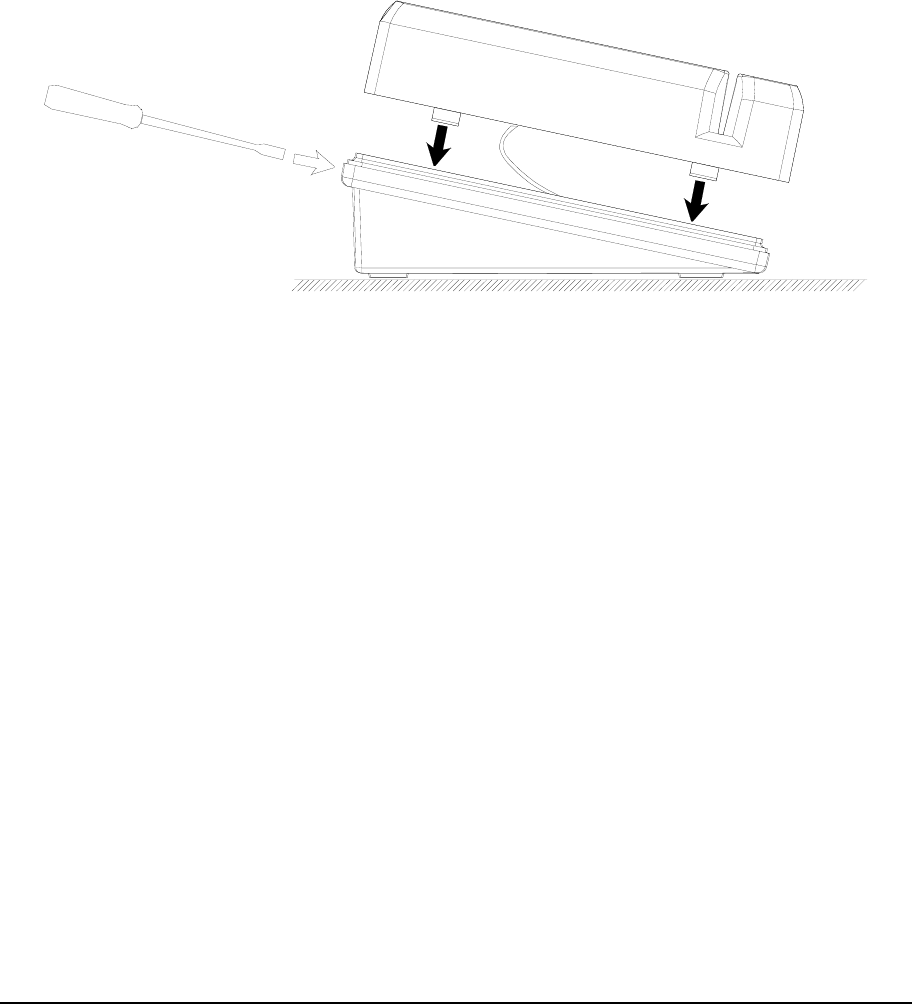
Closing the Terminal (Turnstile-Mounted Assembly)
To close a turnstile-mounted terminal, follow these steps:
1. Unscrew the special closure screw by turning it counterclockwise so that
the terminal closure remains fully open (in the direction of the wedge).
2. Insert the upper shell as indicated in Figure 18.
3. Fasten the special closure screw by turning it clockwise and pushing down
on the shell, so that the fitting is completely secure.
4. Tighten the screw.
Figure 18. Closing the Terminal (Turnstile-Mounted Assembly)
Page 22 Identification via the Service Pin
ACTIVATION
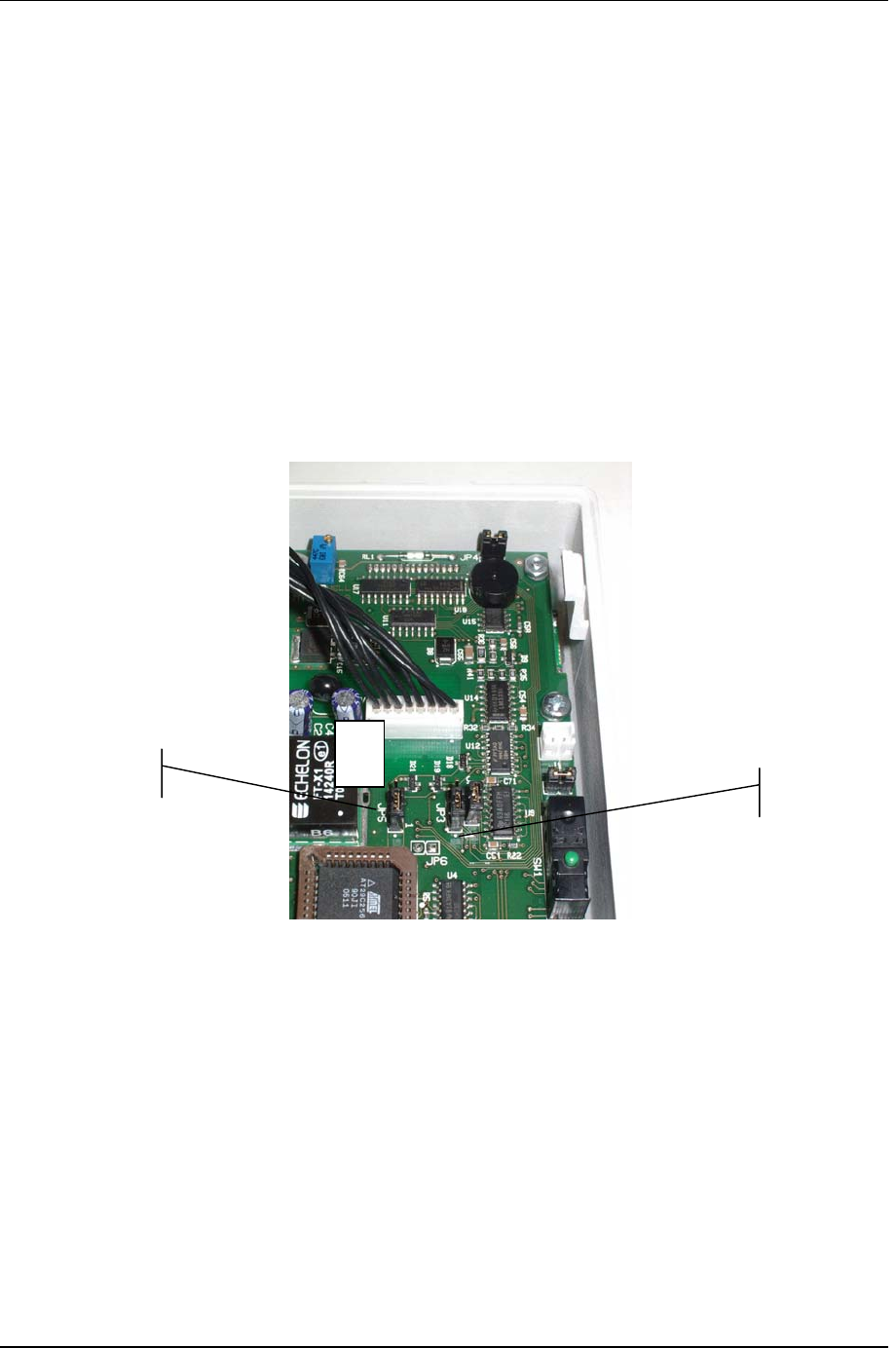
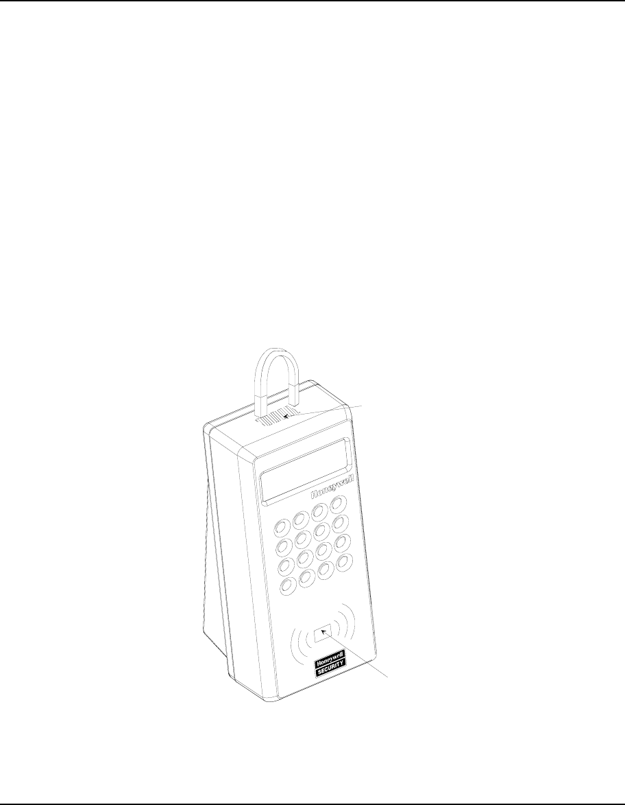
Identification via the Service Pin
To identify the node, you can activate the service pin by means of a relay
reed located inside the unit (see the below figure). This procedure consists of
the following steps:
1. Position a small magnet as illustrated to activate the service pin. This
signal is linked to the yellow central service LED, which flashes throughout
the node configuration procedure.
2. The TemaServer, in response to the service pin, sends a wink command
that makes yellow LED flash three times. This allows you to verify that
communication to and from the TemaServer is working.
3. Check that the service LED remains off after you have completed this
operation.
Figure 19. Using a Magnet to Activate the Service Pin
Magnet
service
LED
service pin
(reed)
Identification via Bar Code Page 23
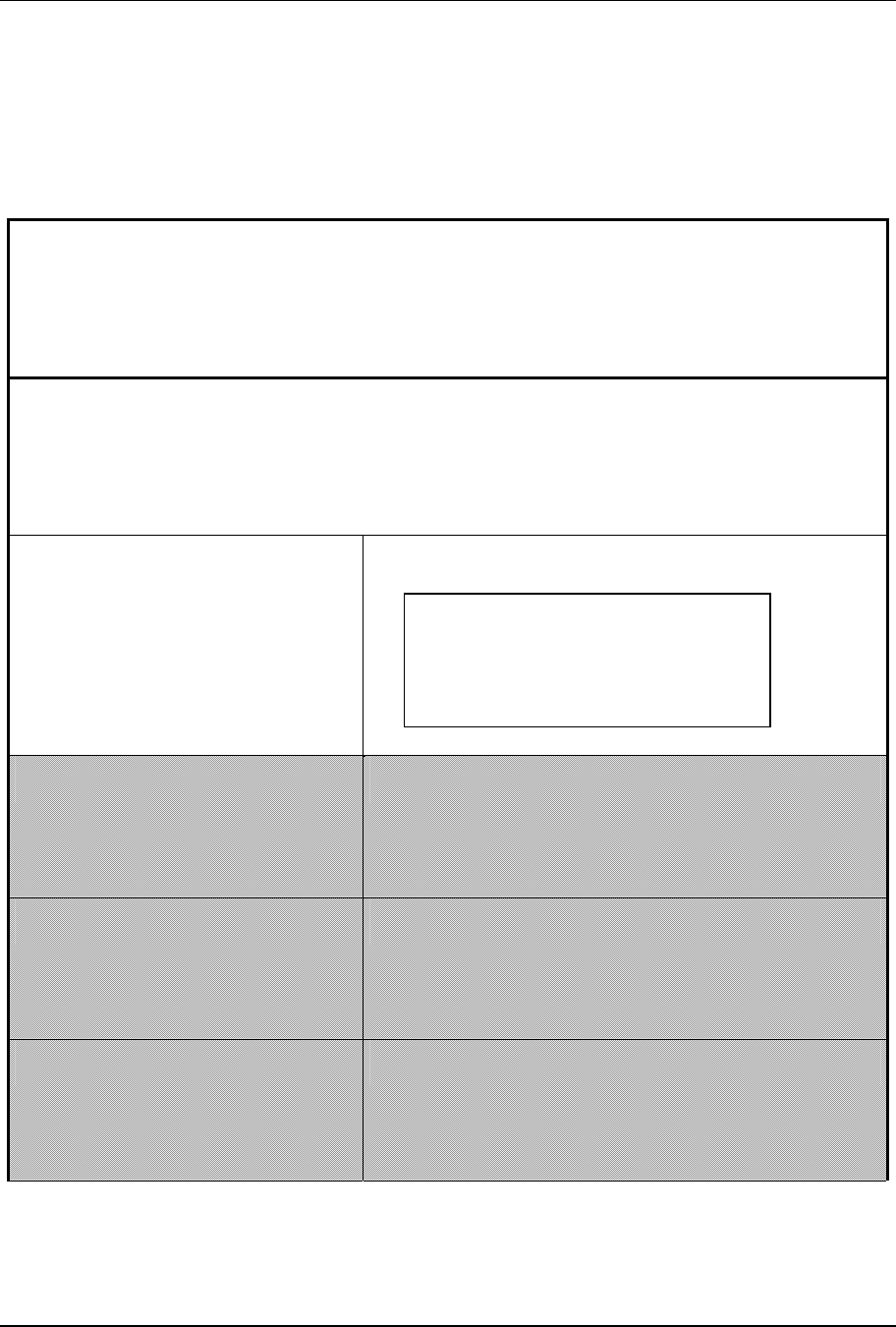
Identification via Bar Code
The components enclosed in the packaging include a bar code label. The
person responsible for installing the terminal must apply this label to the
corresponding identification form, and indicate the location of the terminal in
the appropriate box (see example in Table 5).
Description of location
Office entrance area, first floor -
staircase E
Description of TemaServer
Panel 2 entrance area, first floor
– staircase E
TKC01 (RTU-K01)
TKC02 (RTU-K02)
TKC03 (RTU-K03)
TKC12 (RTU-K12)
NID label
Table 5. Example of Completed Identification Form
X

Page 24 TemaKey TK C12 (RTU-K12 code 1500164xx)
TECHNICAL SPECIFICATIONS
TemaKey TK C12 (RTU-K12 code 1500164xx)
Parameter Value
DC power supply 12VDC±20% 150mA (2W)
Weight 0.4 kg
Size 72x160x75 mm
Protection level IP55
Operational temperature -20 ÷ 60 °C
Storage temperature -20 ÷ 70 °C
Storage relative
humidity
0 ÷ 90 % without condensation
Display Alphanumeric 16x2 – led backlight
Acustic signal 1 Buzzer
LED 1 led with 3 color:
- RED
- Green
- Yellow (Lon service Led)
Keyboard 4 x 4 keypad with soft epoxy / UL treatment on
keys for harsh environment
Proxy receiver 13,56MHz for 14443A / B cards
Reading range: depending on technology of
card.
Typical 7 cm for MIFARE2 full ISO14443A
Typical 4 cm for STM ISO14443B
2 MIFARE® is a registered trademark of Philips Electronics N.V.

TemaKey TK C12 (RTU-K12 code 1500164xx) Page 25
Inputs 2 supervised or digital inputs.
Mode select by JP2
JP2 = Close Î Supervised inputs
JP2 = Open Î Digital inputs
• Supervised inputs with 4 status:
normal, alarm, cut, short
• Digital inputs with status: open or Close
Current 0 to 10mA for each input
(internal reference 5Vdc)
Voltage +14V max.
0V min
Outputs Number 2
Type Power Open drain (MOSFET)
Current 1,2A continuous
5A (0,5sec) impulsive
Voltage 10V...+14V (internal Power
supply)
Voltage (absolute max) 10V...+30V (from
external Power supply).
Current 1,2A [5A / 0,5sec peak max –
inductive load]
Normality NO or NC via Jumper setting
JP3 = 1-2 OUT 1 NO
2-3 OUT 1 NC
JP5 = 1-2 OUT 2 NO
2-3 OUT 2 NC
Wire length connection: it depends on cable
diameter, load current sink and load min
power supply
On state resistance = typical 20 mOhm
Load 1A = 0.02 V

Page 26 TemaKey TK C12 (RTU-K12 code 1500164xx)
Other Jumpers JP4 Î normally close
Close = Buzzer enabled
Open = Buzzer disabled
JP1 Î normaly close (reserved for future use)
JP6 Î normaly open (reserved for future use)
LONWORKS®3 connection Unshielded twisted-pair cable in free topology
(transceiver FTT10A, 78Kbps)
Compliance with
Regulations
Directive EMC 89/336/EEC, 92/31/EEC,
Directive Low Voltage 72/23/EEC, 93/68/EEC:
EN60950, EN55024, EN55022, EN 300 330
Environment friendly
RoHS / WEEE compliant device
Directives 2002/95/EC 2002/96/EC
Optional Parts
TORX screwdriver TX10 code 1500108AA
3 LONWORKS® is a trademark of Echelon Corporation

Recycling Page 27
Recycling
In application of directive 2002/96/EC regarding waste electrical and electronic apparatus, effective beginning 13
August 2005, Honeywell commits, when requested by the customer, to the collection, treatment, recovery, and
disposal of the apparatus produced.
Customers in European Union are advised to dispose this product, at the end of its useful life, as per applicable local
laws, regulations and procedures