Ademco RTU-L19 Access Control Terminal User Manual RTUL19
Honeywell International Inc Access Control Terminal RTUL19
UserManual.wiki
>
Ademco
>
RTU L19 User Manual
manual
Navigation menu
Upload a User Manual
Namespaces
Wiki Guide
HTML
PDF
Info
Views
User Manual
Discussion / Help
Navigation
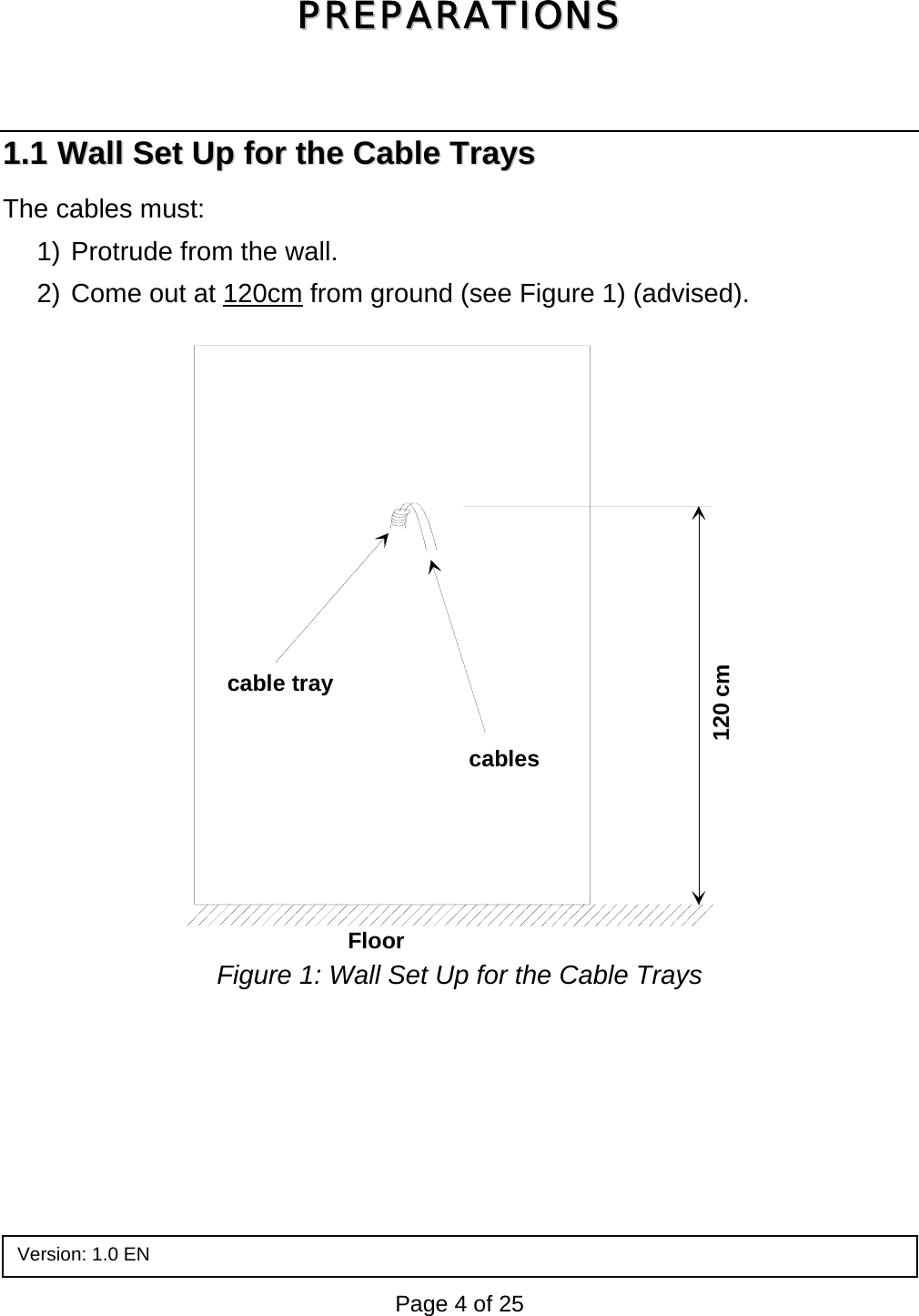
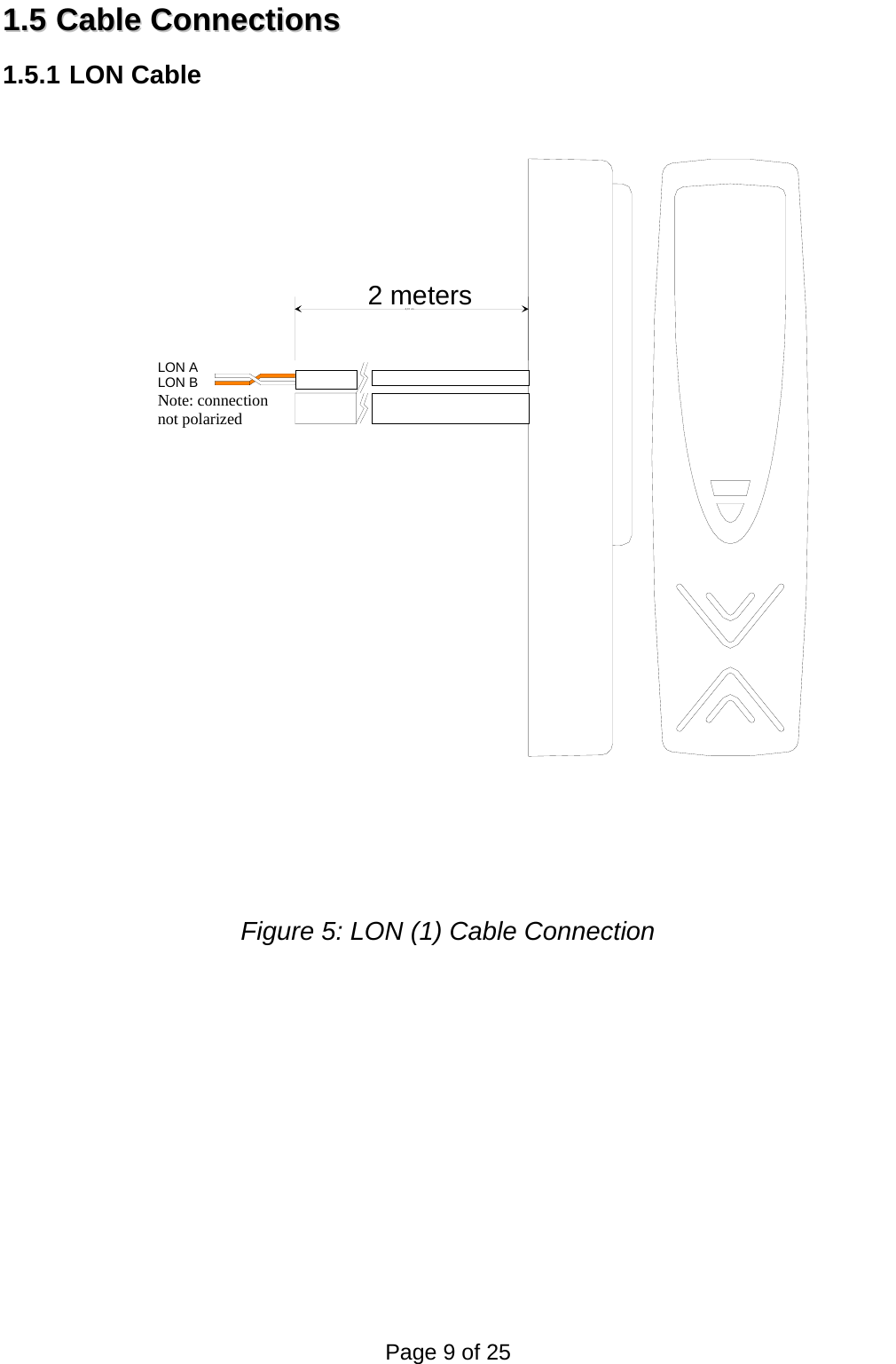
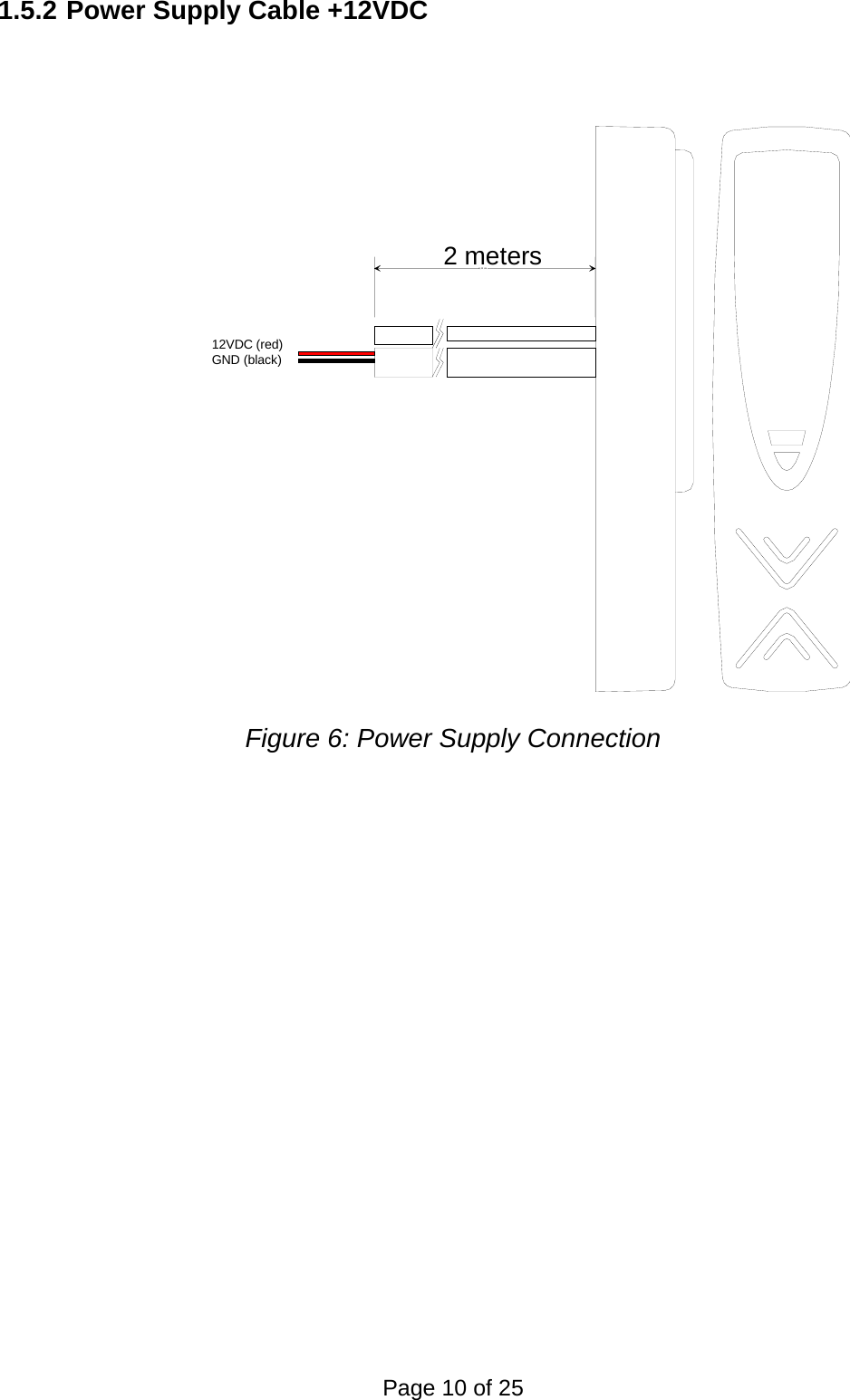
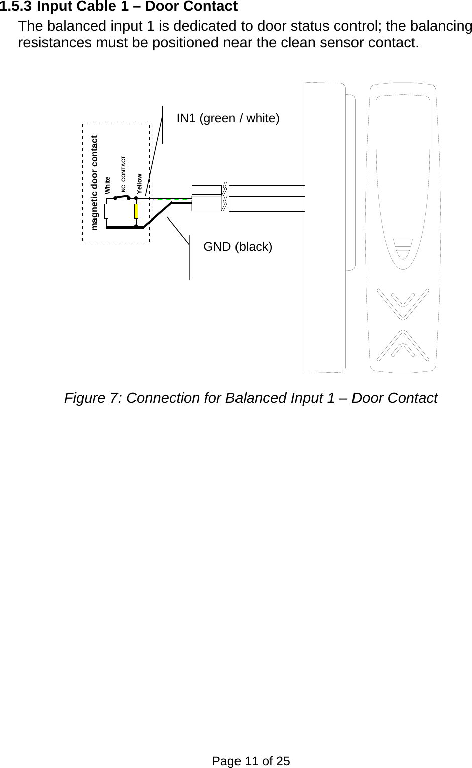
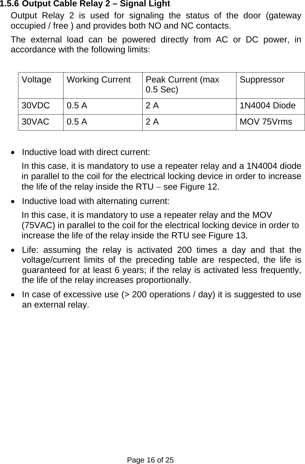
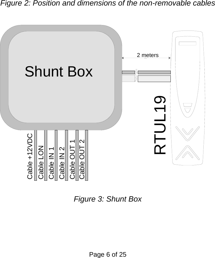
![11..22 EElleeccttrriiccaall CCoonnnneeccttiioonnss The RTU is powered at low voltage (12VDC 160mA), preferably using a power supply module with battery backup (RTU-Qxx), or using an ordinary power supply having the same characteristics. The power cables must be dimensioned as indicated in the table below. The maximum allowable voltage drop on the power cable is 1V. • Cable length(m) = 1V / (I[A] load x 2 x (res [Ohm/km] /1000)) Cabl e Type Ext ensi on [ m] based on l oadAWG mm2 ohm/ Km 160 [ mA] 320 [ mA]12 3. 3 5. 7 548 27414 2 8. 8 355 17816 1. 3 14 223 11218 0. 9 21 149 74200.634924622 0. 35 52 60 30240.2853718 The device is equipped with 2 non-removable cables of 2m length: • Two-pole, twisted, unpolarized cable dedicated to the LON line connection - LON a 0,325 mm2 white - LON b 0,325 mm2 orange • Ten-pole cable, providing the following signals: - +12VDC 0,34 mm2 red - GND 0,34 mm2 black - INPUT 1 + 0,22 mm2 green / white - INPUT 2 + 0,22 mm2 gray / green - RELAY 2 contact C 0,22 mm2 brown - RELAY 2 contact NC 0,22 mm2 white - RELAY 2 contact NO 0,22 mm2 blue - RELAY 1 contact C 0,56 mm2 green - RELAY 1 contact NC 0,56 mm2 yellow - RELAY 1 contact NO 0,56 mm2 gray The signals must be connected using a shunt box with IP protection level in conformance with the type of environment in which it is to be used: - IP55 for moist environments - Recessed box or IP31 at least for inside installations The shunt box must be positioned within the perimeter controlled by the access control system. If necessary, the repeater relays must be inserted inside the box for electrical locking commands and the signal light. Page 5 of 25 2-pole LONcable](https://usermanual.wiki/Ademco/RTU-L19/User-Guide-587398-Page-5.png)
![11..33 LLOONNWWOORRKKSS®® DDaattaa CCaabblleess • The LONWORKS®1 data cables must be double twisted-pair cables • In a free topology configuration, the overall length of the sections must not exceed 500m • In a bus configuration, the overall length of the sections must not exceed 2700m • In the free topology configuration, the 50ohm terminator must be enabled by inserting the appropriate jumper into the FTT10A plug-in on the CTU-PLG06 board inside the TemaServer • In a bus configuration, two terminators must be inserted at the two ends of the bus (resistance of 100ohm 1% ½W) • The LONWORKS®1 data cables must be dimensioned according to the indications in Table 1 Cable Type Extension [m] based on cable capacitance AWG mm2Ohm/Km 50nF/Km 100nF/Km 200nF/Km 500nF/Km 1uF/Km 12 3.3 5.7 2676 1892 1338 846 598 14 2 8.8 2153 1523 1077 681 482 16 1.3 14 1707 1207 854 540 382 18 0.9 21 1394 986 697 441 312 20 0.6 34 1096 775 548 346 245 22 0.35 52 886 626 443 280 198 24 0.2 85 693 490 346 219 155 Table 1: Length/Capacitance of LONWORKS® 1Cables • The FTT10A Echelon® v1.2 User’s Guide suggests using the cables as indicated in Table 2. Make and Model AWG Bus Connection Max Length total [m] Free Topology Connection Node-to-Node Max Length [m] Free Topology - Connection Max Length total [m] Belden 85102 16 2700 500 500 Belden 8471 16 2700 400 500 Level IV (twisted pair, solid, unshielded) 22 1400 400 500 JY (St) 2x2x0,8 (4 solid wires, spiral-twisted, shielded) 20 900 320 500 TIA Cat5 / 900 250 450 Table 2: Suggested LONWORKS® Cables 1 LONWORKS® is a trademark of the Echelon Corporation Page 7 of 25](https://usermanual.wiki/Ademco/RTU-L19/User-Guide-587398-Page-7.png)