Ademco RTU-L19 Access Control Terminal User Manual RTUL19
Honeywell International Inc Access Control Terminal RTUL19
Ademco >
manual
TKL19 (RTUL19)
Installation Manual
Honeywell Installation manual Pagina 1 di 25

CONTENTS
1.1 Wall Set Up for the Cable Trays ......................................................... 4
1.2 Electrical Connections ........................................................................ 5
1.3 LONWORKS® Data Cables ................................................................ 7
1.4 Mounting the Wall Bracket.................................................................. 8
1.5 Cable Connections ............................................................................. 9
1.5.1 LON Cable.............................................................................. 9
1.5.2 Power Supply Cable +12VDC .............................................. 10
1.5.3 Input Cable 1 – Door Contact............................................... 11
1.5.4 Input Cable 2 - Button .......................................................... 12
1.5.5 Output Cable Relay 1- Door Open ....................................... 13
1.5.6 Output Cable Relay 2 – Signal Light .................................... 16
1.6 Mounting the Device on the Wall Bracket......................................... 18
1.7 Identification Using the Service Pin .................................................. 19
1.8 Identification Using the Neuron ID.................................................... 20
2.1 TemaKey TKL19 (RTU-L19 code 1500154xx)................................... 21
2.1.1 Supplied Parts...................................................................... 22
2.1.2 Optional Parts....................................................................... 22
2.2 Recycling .......................................................................................... 23
Page 2 of 25

F
FC
CC
C
N
NO
OT
TI
IC
CE
E
NOTE: This equipment has been tested and found to comply with the limits
for a Class B digital device, pursuant to Part 15 of FCC Rules. These limits
are designed to provide reasonable protection against harmful interference in
a residential installation. This equipment generates, uses and can radiate
radio frequency energy and, if not installed and used in accordance with the
instructions, may cause harmful interference to radio communications.
However, these is no guarantee that interference will not occur in a particular
installation.
If this equipment does cause harmful interference to radio or television
reception, which can be determined by tuning the equipment off and on, the
user is encouraged to try to correct the interference by one or more the
following measures:
-- Reorient or relocate the receiving antenna.
-- Increase the separation between the equipment and receiver.
-- Connect the equipment into an outlet on a circuit different from that to
which the receiver is connected.
-- Consult the dealer or an experienced radio/TV technician for help.
Caution: any modification or change not expressely approved by the party
responsible for compliance could void the user’s authority to operate the
equipment.
Canadian Compliance Statement
This Class B Digital apparatus meets all the requirements of the Canadian
Interference-Causing Equipment Regulations.
Cet appareil numerique de la classe B respecte les exigences du Reglement
sur le material broilleur du Canada.
This device complies with Part 15 of the FCC Rules.
Operation is subject to the following two conditions:
(1) this device may not cause harmful interference, and
(2) this device must accept any interference received,
including interference that may cause undesired operation.
FCC ID: HS9-RTU-L19
Page 3 of 25
1
1.
.2
2
E
El
le
ec
ct
tr
ri
ic
ca
al
l
C
Co
on
nn
ne
ec
ct
ti
io
on
ns
s
The RTU is powered at low voltage (12VDC 160mA), preferably using a
power supply module with battery backup (RTU-Qxx), or using an ordinary
power supply having the same characteristics. The power cables must be
dimensioned as indicated in the table below. The maximum allowable voltage
drop on the power cable is 1V.
• Cable length(m) = 1V / (I[A] load x 2 x (res [Ohm/km] /1000))
Cabl e Type Ext ensi on [ m] based on l oad
AWG mm2 ohm/ Km 160 [ mA] 320 [ mA]
12 3. 3 5. 7 548 274
14 2 8. 8 355 178
16 1. 3 14 223 112
18 0. 9 21 149 74
200.6349246
22 0. 35 52 60 30
240.2853718
The device is equipped with 2 non-removable cables of 2m length:
• Two-pole, twisted, unpolarized cable dedicated to the LON line
connection
- LON a 0,325 mm2 white
- LON b 0,325 mm2 orange
• Ten-pole cable, providing the following signals:
- +12VDC 0,34 mm2 red
- GND 0,34 mm2 black
- INPUT 1 + 0,22 mm2 green / white
- INPUT 2 + 0,22 mm2 gray / green
- RELAY 2 contact C 0,22 mm2 brown
- RELAY 2 contact NC 0,22 mm2 white
- RELAY 2 contact NO 0,22 mm2 blue
- RELAY 1 contact C 0,56 mm2 green
- RELAY 1 contact NC 0,56 mm2 yellow
- RELAY 1 contact NO 0,56 mm2 gray
The signals must be connected using a shunt box with IP protection level
in conformance with the type of environment in which it is to be used:
- IP55 for moist environments
- Recessed box or IP31 at least for inside installations
The shunt box must be positioned within the perimeter controlled by the
access control system.
If necessary, the repeater relays must be inserted inside the box for
electrical locking commands and the signal light.
Page 5 of 25
2-pole LON
cable
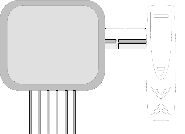
Figure 2: Position and dimensions of the non-removable cables
4,20 cm
2 meters
Shunt Box
Cable +12VDC
Cable LON
Cable IN 1
Cable IN 2
Cable OUT 1
Cable OUT 2
RTUL19
Figure 3: Shunt Box
Page 6 of 25
1
1.
.3
3
L
LO
ON
NW
WO
OR
RK
KS
S®
®
D
Da
at
ta
a
C
Ca
ab
bl
le
es
s
• The LONWORKS®1 data cables must be double twisted-pair cables
• In a free topology configuration, the overall length of the sections must not
exceed 500m
• In a bus configuration, the overall length of the sections must not exceed
2700m
• In the free topology configuration, the 50ohm terminator must be enabled
by inserting the appropriate jumper into the FTT10A plug-in on the CTU-
PLG06 board inside the TemaServer
• In a bus configuration, two terminators must be inserted at the two ends of
the bus (resistance of 100ohm 1% ½W)
• The LONWORKS®1 data cables must be dimensioned according to the
indications in Table 1
Cable Type Extension [m] based on cable capacitance
AWG mm2Ohm/Km 50nF/Km 100nF/K
m 200nF/K
m 500nF/K
m 1uF/Km
12 3.3 5.7 2676 1892 1338 846 598
14 2 8.8 2153 1523 1077 681 482
16 1.3 14 1707 1207 854 540 382
18 0.9 21 1394 986 697 441 312
20 0.6 34 1096 775 548 346 245
22 0.35 52 886 626 443 280 198
24 0.2 85 693 490 346 219 155
Table 1: Length/Capacitance of LONWORKS
®
1Cables
• The FTT10A Echelon® v1.2 User’s Guide suggests using the cables as
indicated in Table 2.
Make and Model AW
G Bus
Connection
Max Length
total [m]
Free Topology
Connection Node-
to-Node Max
Length [m]
Free Topology -
Connection
Max Length total
[m]
Belden 85102 16 2700 500 500
Belden 8471 16 2700 400 500
Level IV (twisted pair,
solid, unshielded) 22 1400 400 500
JY (St) 2x2x0,8 (4
solid wires, spiral-
twisted, shielded)
20 900 320 500
TIA Cat5 / 900 250 450
Table 2: Suggested LONWORKS
®
Cables
1 LONWORKS® is a trademark of the Echelon Corporation
Page 7 of 25
1
1.
.4
4
M
Mo
ou
un
nt
ti
in
ng
g
t
th
he
e
W
Wa
al
ll
l
B
Br
ra
ac
ck
ke
et
t
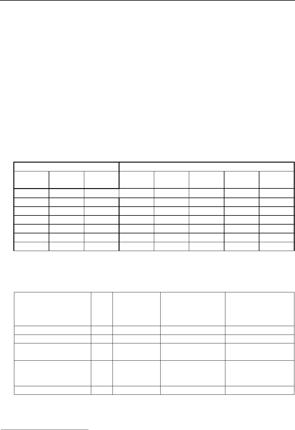
Mount the bracket onto the wall as follows:
1. Placing the bracket against the wall to indicate the proper positions of the
holes, make the holes for the two bolts that will go into the wall to hold the
bracket (the bolts are included in the installation kit)
2. Make sure that the cable tray bathces with the hole for the passage of the
cables
3. Screw in the bolts.
Hole for Cables
Hole for inserting bolt and
screw to press against the
anti-removal/anti-open
tamper
Holes for wall
mounting
Figure 4: Wall Bracket: Front View and Side View
Page 8 of 25
1
1.
.5
5
C
Ca
ab
bl
le
e
C
Co
on
nn
ne
ec
ct
ti
io
on
ns
s
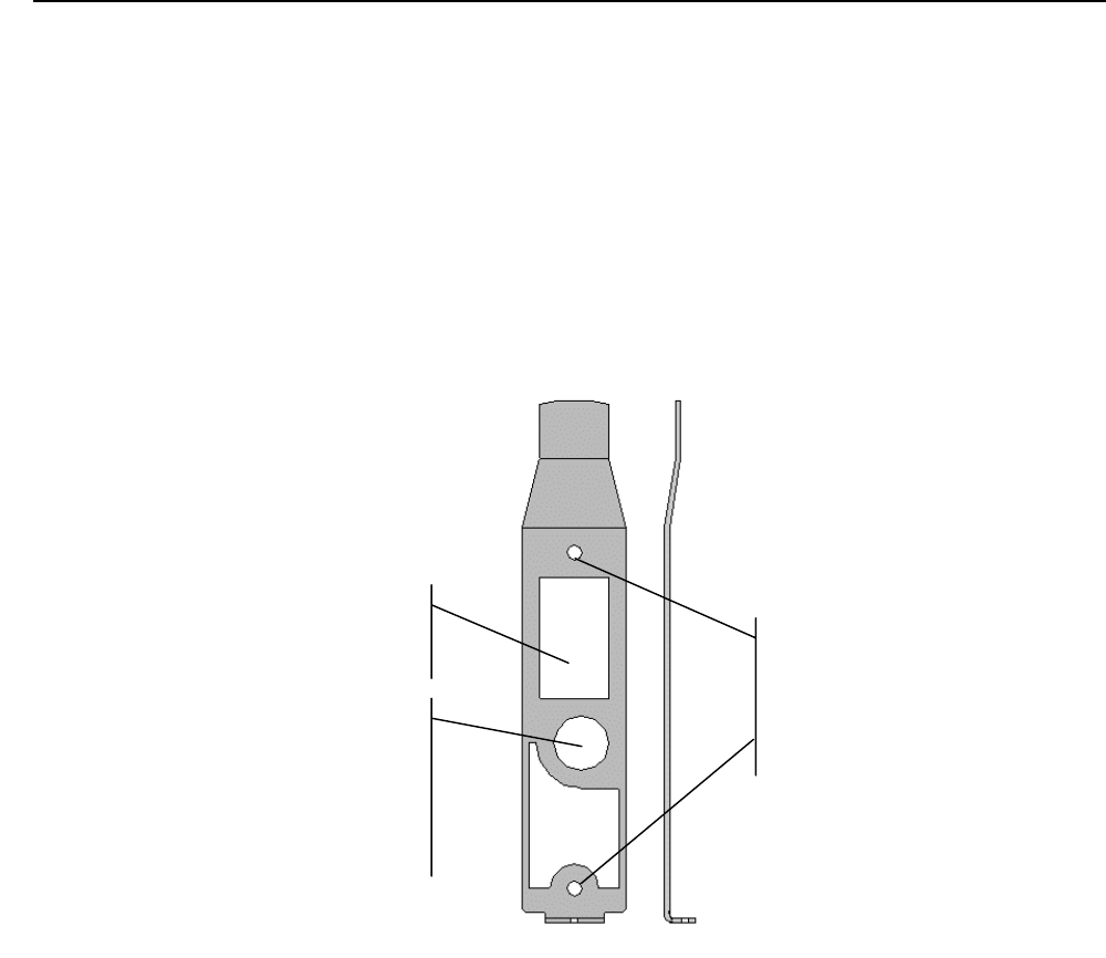
1.5.1 LON Cable
6,10 cm
2 meters
LON A
LON B
Note: connection
not polarized
Figure 5: LON (1) Cable Connection
Page 9 of 25
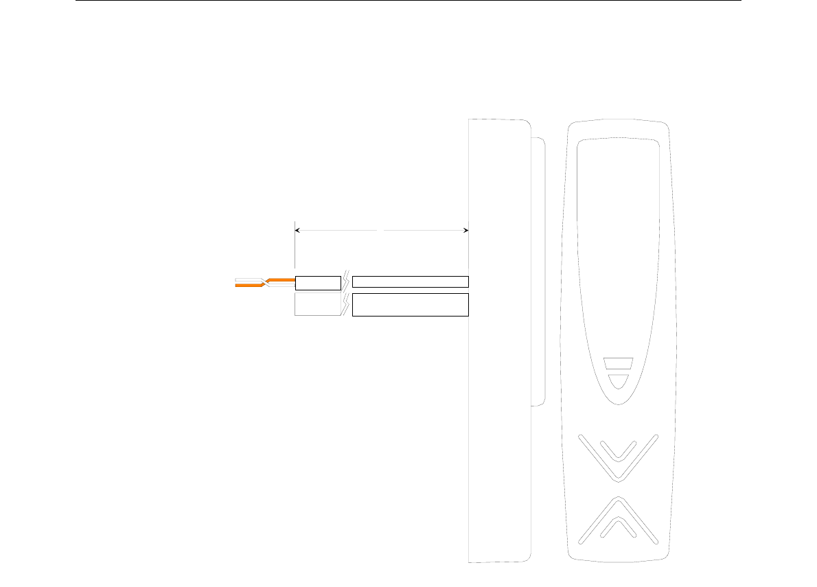
1.5.2 Power Supply Cable +12VDC
6,10 cm
2 meters
12VDC (red)
GND (black)
Figure 6: Power Supply Connection
Page 10 of 25
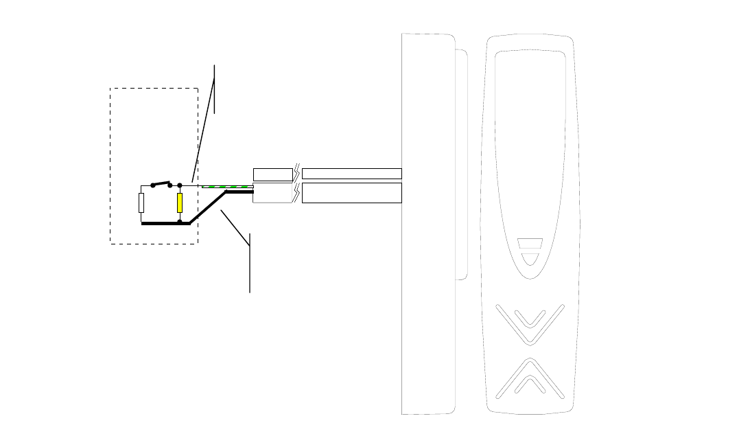
1.5.3 Input Cable 1 – Door Contact
The balanced input 1 is dedicated to door status control; the balancing
resistances must be positioned near the clean sensor contact.
White
Yellow
magnetic door contact
NC CONTACT
Figure 7: Connection for Balanced Input 1 – Door Contact
GND (black)
IN1 (green / white)
Page 11 of 25
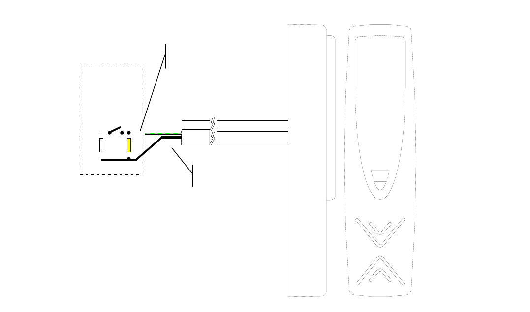
1.5.4 Input Cable 2 - Button
Balanced input 2 is dedicated to status control of the Open button; the
balancing resistances must be positioned near the clean contact of the
button.
White
Yellow
button contact
NO CONTACT
GND
IN2 (green / gray)
Figure 8: Connection for Balanced Input 2 - Button
Page 12 of 25

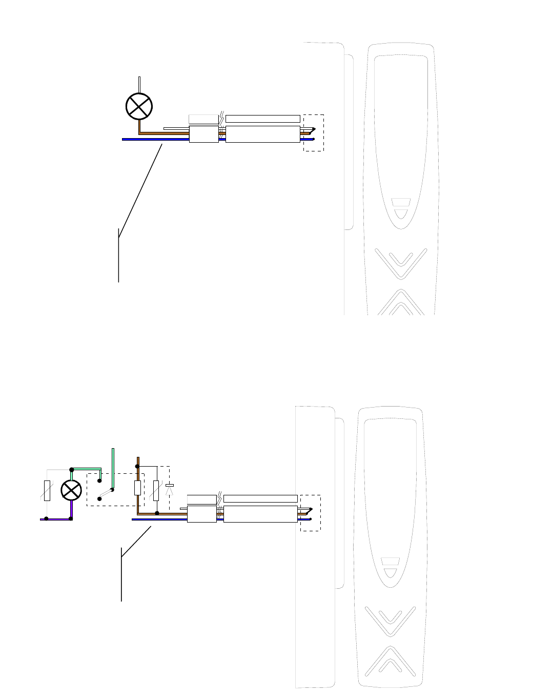
1.5.5 Output Cable Relay 1- Door Open
The Relay 1 output is used for door control. It makes both NO and NC
contacts available.
The external load can be powered directly by AC or DC, in accordance
with the following limits:
- Minimum Load: 12VDC / 10mA
Voltage Working Current Peak Current
max 0.5 Sec
(inductive load)
Suppressor
12VDC 3A 10A 1N4004 Diode
30VDC 2A 10A 1N4004 Diode
42VDC 0.5A 7A 1N4004 Diode
42VAC 0.5A 7A MOV 75Vrms
• Inductive load with direct current:
In this case it is mandatory to use the 1N4004 diode, which is provided,
(or an equivalent) in parallel to the coil of the electrical locking device, to
increase the life of the relay inside the RTU – see Figure 9.
• Inductive load with alternating current:
In this case it is mandatory to use the MOV (75VAC), which is provided,
(or an equivalante) in parallel to the coil of the electrical locking device,
to increase the life of the relay inside the RTU − see Figure 10.
• Life: assuming the relay is activated 200 times a day and that the
voltage/current limits of the preceding table are respected, the life is
guaranteed for at least 6 years; if the relay is activated less frequently,
the life of the relay increases proportionally.
In case of excessive use (> 200 operations / day) it is suggested to use
an external relay.
Page 13 of 25
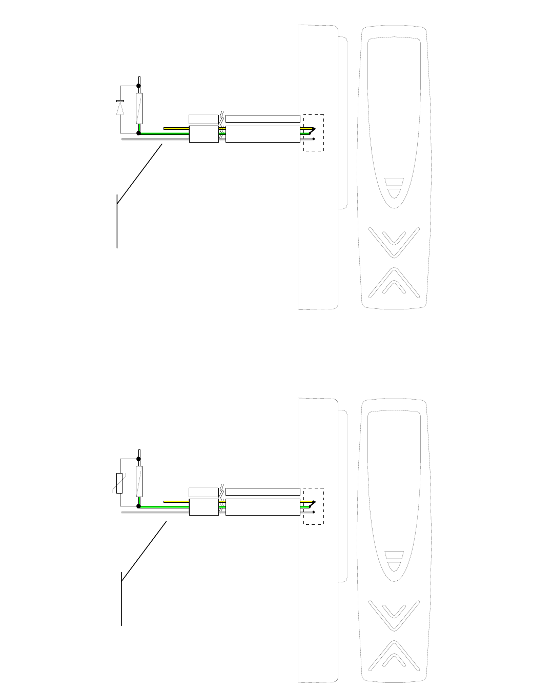
VEXT _+VDC
VEXT_GND
coil for electrical locking device/repeater
1N4004
Diode Transient
Suppressor
Relay 1
Green = C
Yellow = NC
Gray = NO
Figure 9: Connection for Output Relay 1 (NO) – Door Open – DC Voltage
VEXT_Vac1
VEXT _Vac2
Bobina elettroserratura / relè di ripetizione
Mov75Vac
Soppressore
di transienti
Rele 1
Green = C
Yellow = NC
Gray = NO
Figure 10: Connection for Output Relay 1 (NO) – Door Open – AC Voltage
Page 14 of 25
1.5.5.1 Using an External Relay
In case of excessive use or use under elevated current or voltage, you must
insert a relay capable of supporting the load for a higher number of
operations.
The coil for the repeater relay must always be equipped with transient
suppressors, as can be seen in Figures 9 and 10.
It is also suggested to use a transient suppressor on the load in order to
prolong the life of the external relay.
VEXT_relay
VEXT _relay
coil for repeater relay
Transient Suppressor:
Vext AC = Mov75Vac
Vext DC = diodo 1N4004
Relay 1
Mov75Vac
Transient
Suppressor
Vac
Vac
C
NC NO
coil for electrical locking device/repeater
Figure 11: Connection for Output Relay 1 (NO) – External Relay
Page 15 of 25

1.5.6 Output Cable Relay 2 – Signal Light
Output Relay 2 is used for signaling the status of the door (gateway
occupied / free ) and provides both NO and NC contacts.
The external load can be powered directly from AC or DC power, in
accordance with the following limits:
Voltage Working Current Peak Current (max
0.5 Sec) Suppressor
30VDC 0.5 A 2 A 1N4004 Diode
30VAC 0.5 A 2 A MOV 75Vrms
• Inductive load with direct current:
In this case, it is mandatory to use a repeater relay and a 1N4004 diode
in parallel to the coil for the electrical locking device in order to increase
the life of the relay inside the RTU − see Figure 12.
• Inductive load with alternating current:
In this case, it is mandatory to use a repeater relay and the MOV
(75VAC) in parallel to the coil for the electrical locking device in order to
increase the life of the relay inside the RTU see Figure 13.
• Life: assuming the relay is activated 200 times a day and that the
voltage/current limits of the preceding table are respected, the life is
guaranteed for at least 6 years; if the relay is activated less frequently,
the life of the relay increases proportionally.
• In case of excessive use (> 200 operations / day) it is suggested to use
an external relay.
Page 16 of 25
VEXT
VEXT
Signaling Device (LED)
Relay 2
Brown = C
White = NC
Blue = NO
Figure 12: Connection for Output Relay 2 (NO) – Resistive Load – AC/DC
Voltage
VEXT_relay
VEXT _relay
coil for repeater relay
Transient Suppressor:
Vext AC = Mov75Vac
Vext DC = diodo 1N4004
Relay 2
Mov x Vac
Transient
Suppressor
Vac_lamp
Vac_lamp
C
NC NO
Figure 13: Connection for Output Relay 2 (NO) – Inductive Load – Repeater
Relay
Brown = C
White = NC
Blue = NO
Page 17 of 25
1
1.
.6
6
M
Mo
ou
un
nt
ti
in
ng
g
t
th
he
e
D
De
ev
vi
ic
ce
e
o
on
n
t
th
he
e
W
Wa
al
ll
l
B
Br
ra
ac
ck
ke
et
t
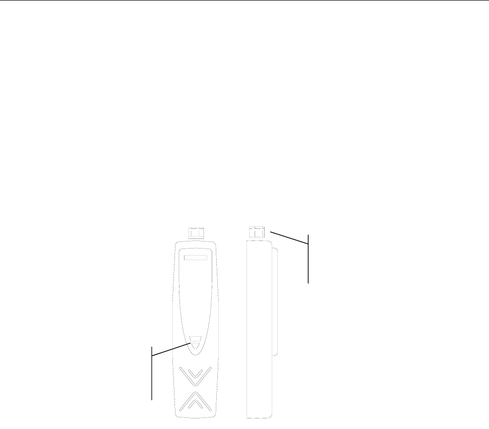
Figure 14: Mounting
1) The RTUL19 is positioned atop the wall bracket protrusion
2) The back part is aligned with the wall by rotating
3) The RTUL19 is mounted onto the bracket using screws
Page 18 of 25
ACTIVATION
1
1.
.7
7
I
Id
de
en
nt
ti
if
fi
ic
ca
at
ti
io
on
n
U
Us
si
in
ng
g
t
th
he
e
S
Se
er
rv
vi
ic
ce
e
P
Pi
in
n
To identify the node, you can call the service pin using the relay-reed found
inside the device (see Figure 15). Use the following steps for this procedure:
1. Place a small magnet as indicated in Figure 15 to call the service pin. The
signal is linked to the yellow service LED (at the center), which will blink
throughout the operation.
2. The TemaServer will send a wink command in response to the service pin,
which lights the yellow LED and the buzzer three times. This allows you to
verify that communications are operational to and from the TemaServer.
3. Check to see that the service LED is off at the end of the operation.
Position of
magnet
The LED
goes
yellow
Figure 15: Calling the Service Pin Using a Magnet
Page 19 of 25
1
1.
.8
8
I
Id
de
en
nt
ti
if
fi
ic
ca
at
ti
io
on
n
U
Us
si
in
ng
g
t
th
he
e
N
Ne
eu
ur
ro
on
n
I
ID
D
The label with the neuron ID that comes with the kit must be applied by the
installer on the appropriate identification sheet. You also must indicate the
location of the terminal in the appropriate box (see example in Table 3).
Description of Location
Entrance to Offices, First Floor,
Stairway E
Description of TemaServer
Panel2, Entrance, First Floor,
Stairway E
RTUL19
Table 3: Example of Compiled Identification Sheet
Page 20 of 25

TECHNICAL DATA
T
Te
em
ma
aK
Ke
ey
y
T
TK
KL
L1
19
9
(
(R
RT
TU
U-
-L
L1
19
9
c
co
od
de
e
1
15
50
00
01
15
54
4x
xx
x)
)
Parameter Value
12VDC±15% 100mA nominal (1.4W),
160mA max (2W)
Power Supply
Weight 0.3 kg
Dimensions 156 Lu x 40 La x 27 sp mm
Degree of Protection IP55
-20 to 60 °C
Operational
Temperature
-20 to 70 °C
Storage Temperature
0 to 95 % without condensation
Relative Humidity of
Storage
LED 1 LED tricolor Red / Green / Yellow
Buzzer 1
Inputs 2 balanced inputs with 4 statuses:
normal, alarm, cut, short
Output Relay 1 Electrical Locking Device Command
• Contacts: C / NC / NO (see page 13)
Output Relay 2 Lamp Command
• Contacts: C / NC / NO (see page 16)
Antenna proxy 125KHz for HID cards
reading distance 0 to 40 mm
(MD-15W internal controller)
LONWORKS®2
Connection "Free Topology" type connected with
unshielded double twisted pair cable
FT3120 Smart Transceiver, 78Kbps
Conformance to Norms
Directive EMC 89/336/EEC, 92/31/EEC,
Low Voltage Directive 72/23/EEC, 93/68/EEC:
EN60950 / EN55022-B / ETSI EN300-330 / EN55024
FCC
This device complies with Part 15 of the FCC Rules.
Operation is subject to the following two conditions:
(1) this device may not cause harmful interference, and
(2) this device must accept any interference received,
including interference that may cause undesired operation.
FCC ID: HS9-RTU-L19
2 LONWORKS® is a trademark of the Echelon Corporation
Page 21 of 25

1.8.1 Supplied Parts
KIT of resistances for
input balancing 2 White resistances
2 Yellow resistances
Fisher bolts for wall
mounting 2 (S4 type) + screws
Fisher bolt for tamper 1 (S4 type) + screws
1N4004 Diode 2
MOV 75Vrms 2
1.8.2 Optional Parts
TORX TX10 Screwdriver Code 1500108AA
Page 22 of 25
1
1.
.9
9
R
Re
ec
cy
yc
cl
li
in
ng
g
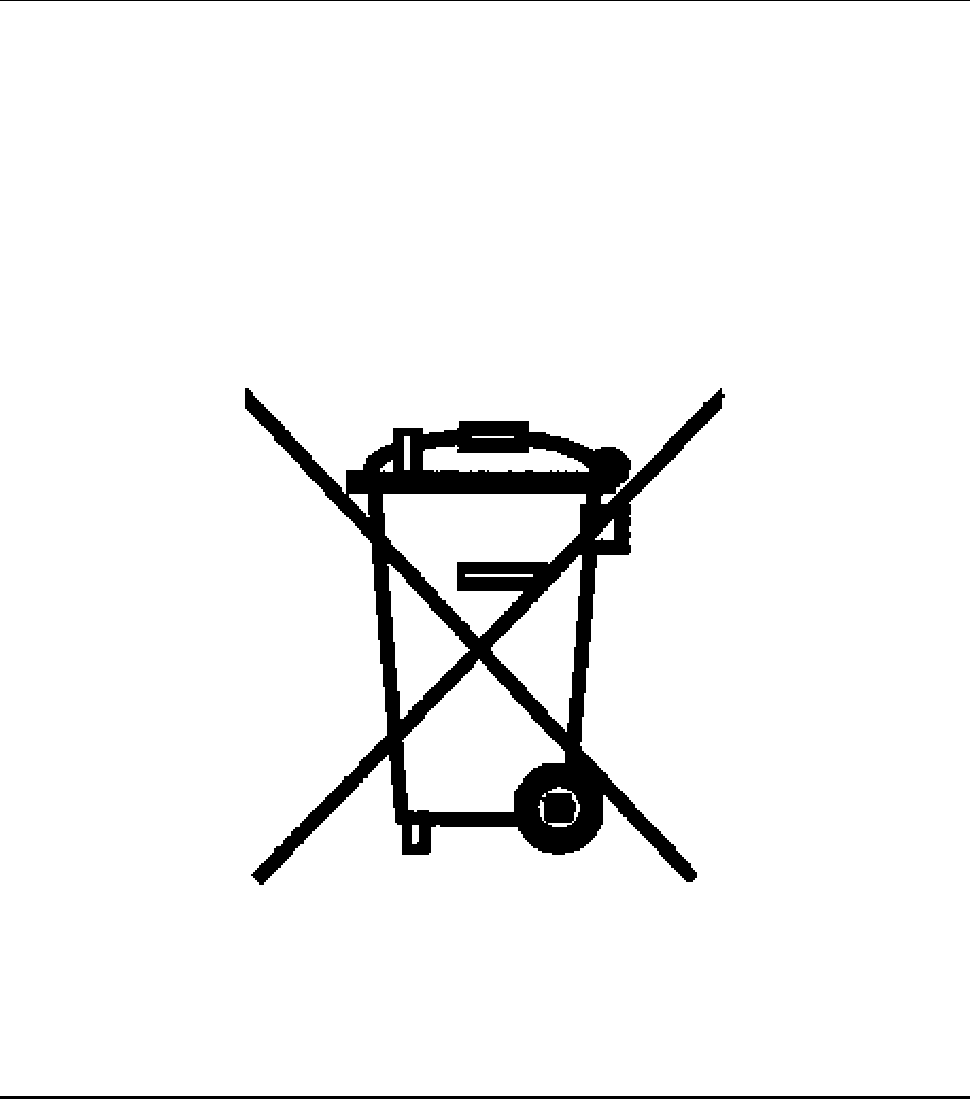
In application of directive 2002/96/EC regarding electrical and electronic waste devices, in vigor from 13 August 2005,
Honeywell engages, when requested by the customer, to the collection, treatment, recovery, and proper disposal of all
devices produced.
All users within the European Union are hereby informed of the requirement for the proper elimination of the product as
regulated by laws, rules, and local procedures.
Page 23 of 25
Notes:
Page 24 of 25
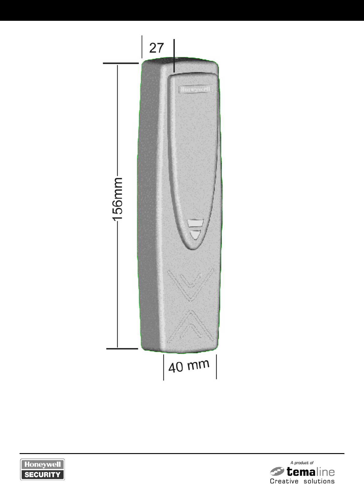
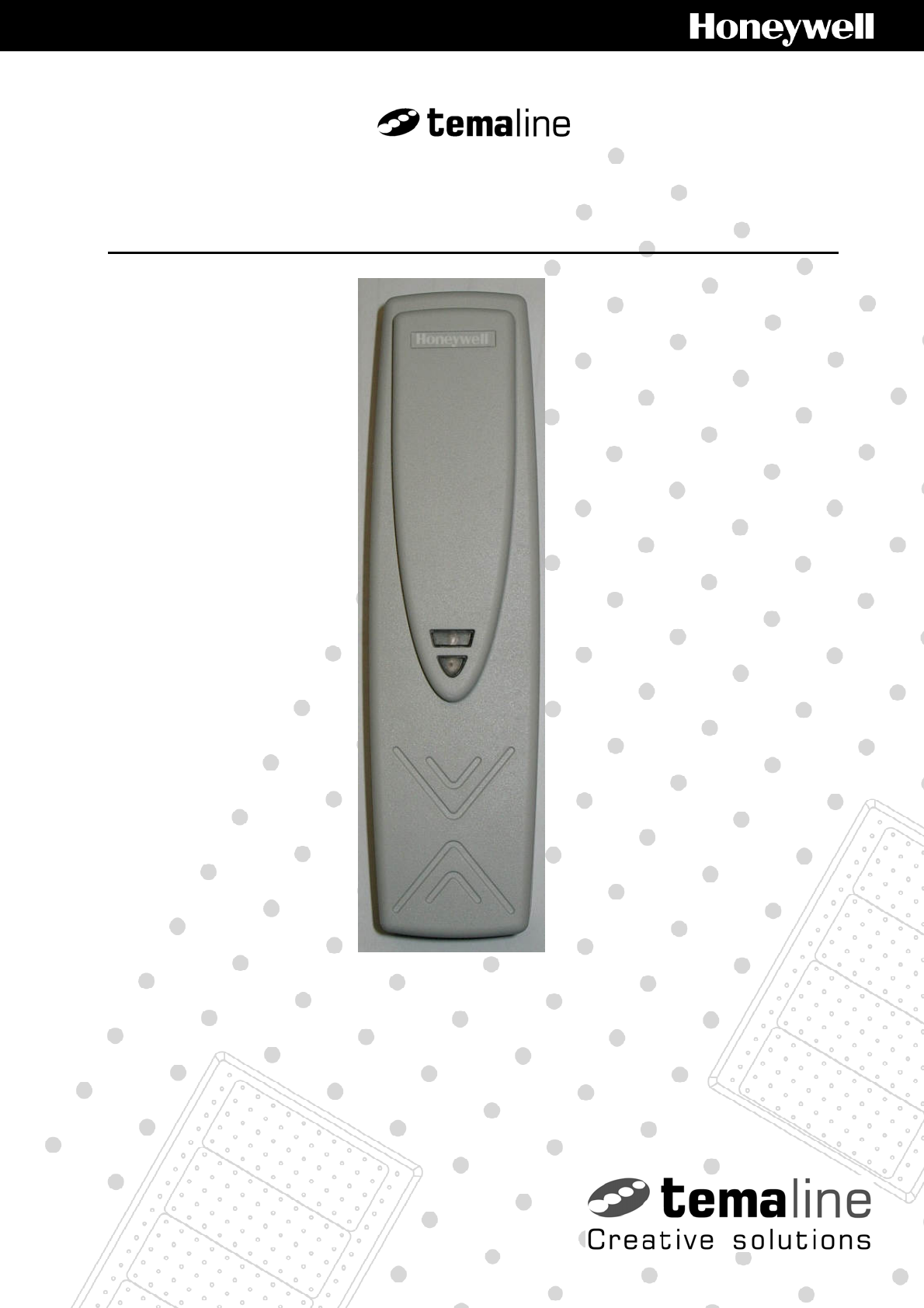
Figure 16: Temakey TKL19
Page 25 of 25