Ademco THX9001R01 Thermostat THX9001R01 User Manual manual
Honeywell International Inc Thermostat THX9001R01 manual
UserManual.wiki
>
Ademco
>
THX9001R01 User Manual
manual
Navigation menu
Upload a User Manual
Namespaces
Wiki Guide
HTML
PDF
Info
Views
User Manual
Discussion / Help
Navigation
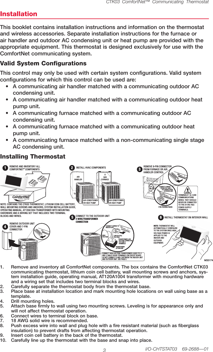
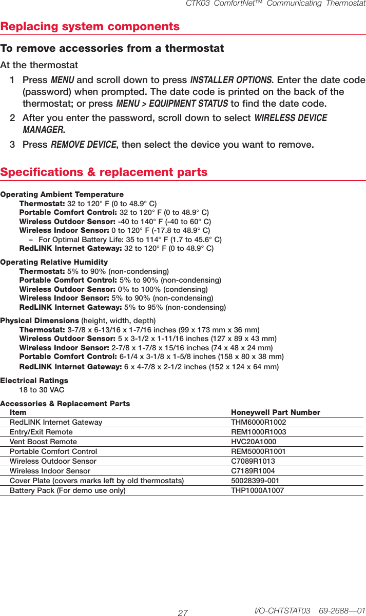
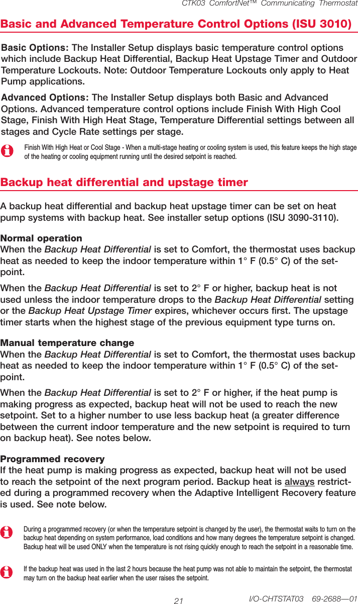
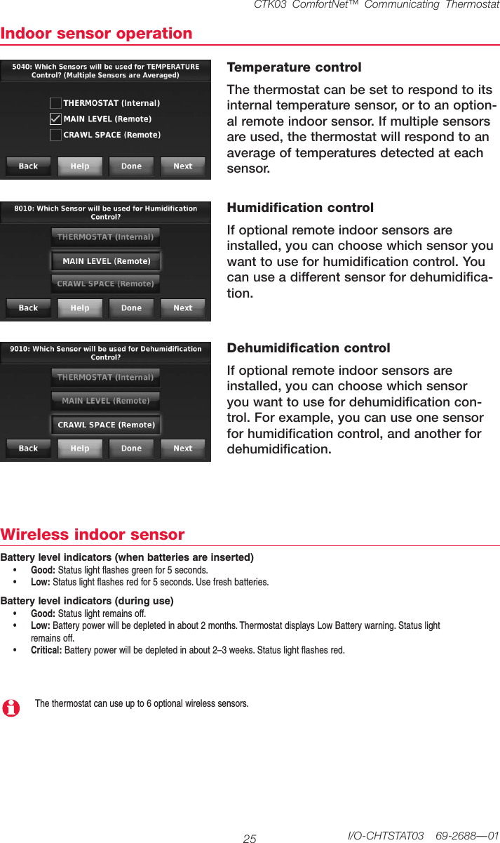
![System Installation Guide669-2688—01 I/O-CHTSTAT03M32940[If no wireless accessories are used, skip to Section 3.]Portable Comfort ControlInstall 2 fresh AAA alkaline batteries Install 3 fresh AA alkaline batteriesOutdoor air sensor Indoor air sensorInstall 2 fresh AA lithium batteriesPower optional accessories2TheHoneywellRedLINKInternetGatewaygivesyourcustomersremoteaccesstohomeclimate-controlsystemsfromanylocationwithInternetaccess.UsingaWebbrowser,userscanreviewandadjustindoortemperature, systemmodeandothersettings.TheGatewaycanalsosendalertstoasmanyas6emailaddressesifaproblemoccurs.RedLINK™ Internet GatewayConnect power cord to an electrical outlet not controlled by a wall switchConnect RedLINK Gateway to a router or modem with Ethernet cable (RJ45).MCR32937 MCR32938 MCR32939](https://usermanual.wiki/Ademco/THX9001R01/User-Guide-1671543-Page-6.png)
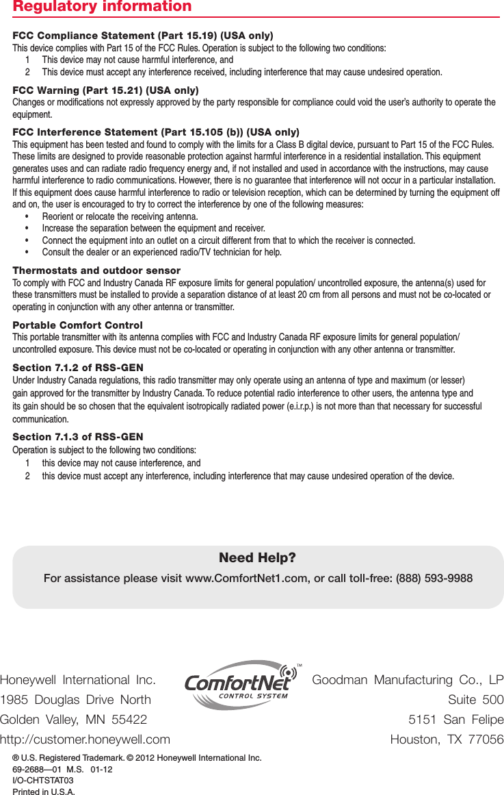
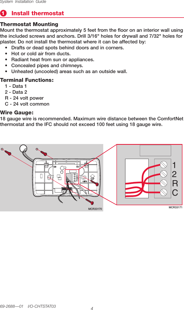
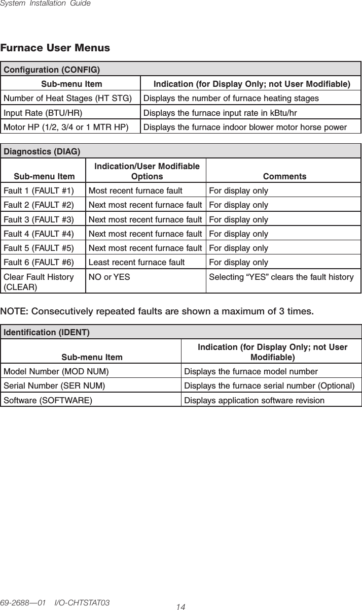
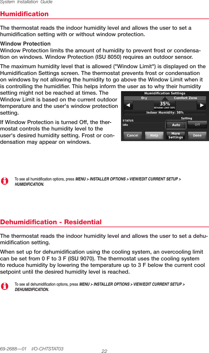
![CTK03 ComfortNet™ Communicating Thermostat11 I/O-CHTSTAT03 69-2688—01Mount optional accessories1 Mountthesensoronaverticalexteriorwall,atleast6inchesbelowanyoverhang.Choosealocationprotected from direct sunlight.2 Placesensorsecurelyinbracket,facingawayfromwall.5M28491M28849A[If no sensors are used, skip to Section 6.]To install outdoor air sensorTo install indoor air sensorTo install Entry/Exit Remote or Vent Boost Remote1 Removethewallplateandmountit4to6feetabovetheflooronaninteriorwall.Drill3/16-inchholesfordrywall,7/32-inchforplaster.2 Attachsensorsecurelytowallplateasshown.Mounting the remote is optional.1 Removethefrontcoverfromtheremote.2 Useprovidedscrewsandwallanchors to fasten the remote to the wall.Drill3/16-inchholesfordrywall,7/32-inchforplaster.3 Replacethecoverontheremote.M32936AM33095Do not install the indoor air sensor where it can be affected by:• Draftsordeadspotsbehinddoorsandincorners.• Hotorcoldairfromducts.• Radiantheatfromsunorappliances.• Concealedpipesandchimneys.• Unheated(uncooled)areassuchasanoutsidewall](https://usermanual.wiki/Ademco/THX9001R01/User-Guide-1671543-Page-11.png)
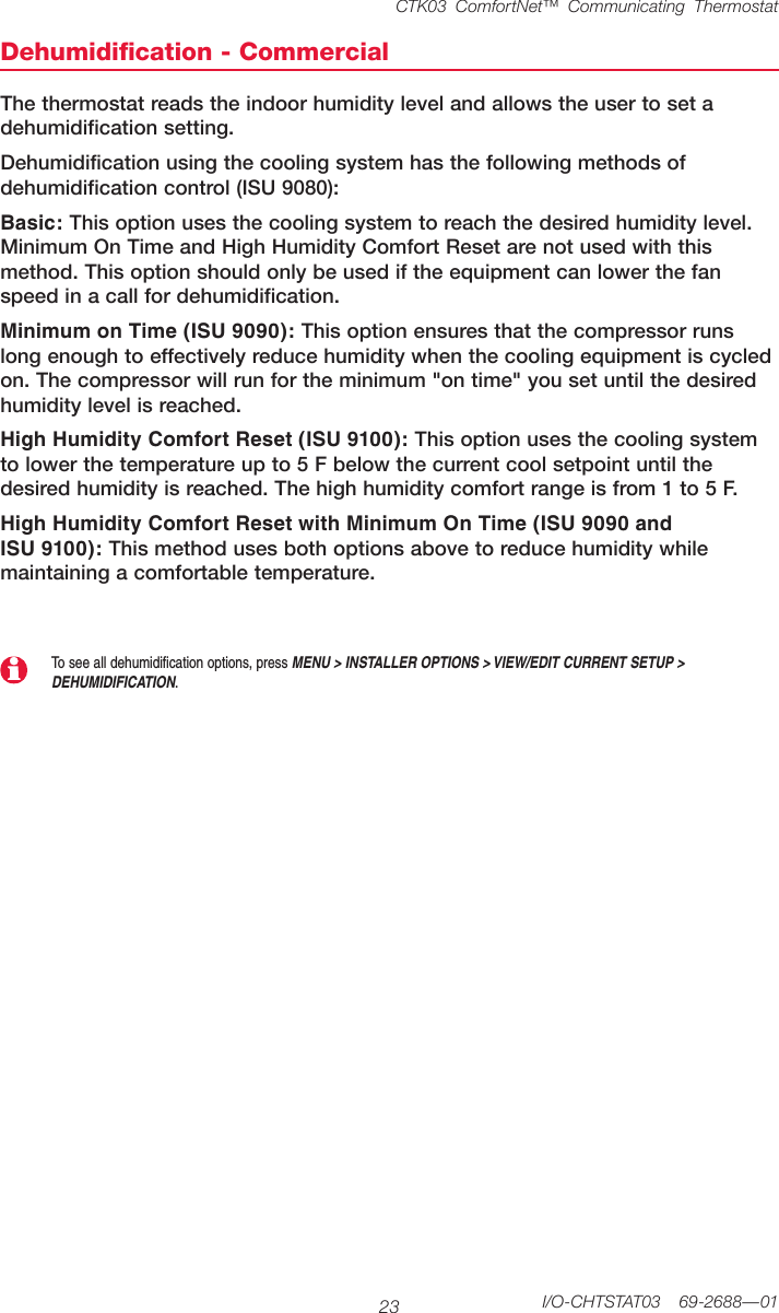
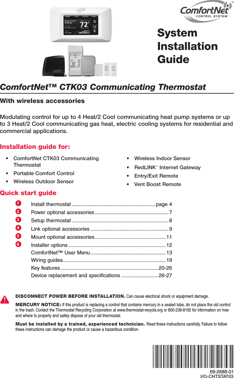
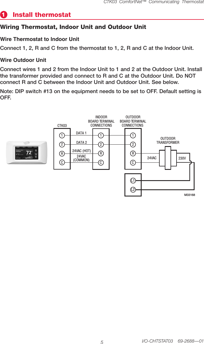
![System Installation Guide2669-2688—01 I/O-CHTSTAT03Alerts LogMENU > INSTALLER OPTIONS > DATA LOGS > ALERTS LOGThethermostatsavesthemostrecent25alerts.Itrecordsthedate,time,alertstatus(snoozed,dismissed,recovered),anddiagnosticinformationtohelpyouidentifyandcorrectproblems.User Interactions LogMENU > INSTALLER OPTIONS > DATA LOGS > USER INTERACTIONS LOGCheckthislogtofindoutifaproblemwascausedbyanaccidentalusererror.Thelogshowsmostchangesmadetothermostatsettings,bytimeanddate,anddescribeswhatchangewasmade.Thethermostatrecordsthemostrecent250changes.Youcanquicklysearchthembydateandtime,orbyfunction.Thisfeaturecanbeturnedoffifnecessary,so that no user interactions are recorded.Examples:* [date, time] Heattemperaturesetto80°F* [date, time] SystemmodesettoOff* [date, time] Installersetupchanged—heatingequipmenttypeReplacing system componentsFollowstepsbelowtodisconnectthethermostatandRedLINKaccessories.To replace a thermostatAtthePortableComfortControl1 Pressandholdtheblankspace(orarrowifpresent)inthelowerrighthandcornerofthescreen until the display changes.2 PressREMOVE, then YES to disconnect from the old thermostat.AttheIndoorSensor,Entry/ExitRemote,VentBoostRemote,RedLINKInternetGatewayorTrueSTEAMWirelessAdapter1 PressandholdtheCONNECTbuttonontheRedLINKaccessoryuntilthestatuslightglowsamber(holdforabout10seconds).Thiswilldisconnectthedevicefromtheoldthermostat.Re-connectRedLINKaccessories1 Followthestepsin“Linkoptionalaccessoriestowirelessnetwork”onpage9.MCR32958Press and hold in lower right corner of screen](https://usermanual.wiki/Ademco/THX9001R01/User-Guide-1671543-Page-26.png)