Ademco THX9001R01 Thermostat THX9001R01 User Manual manual
Honeywell International Inc Thermostat THX9001R01 manual
Ademco >
manual
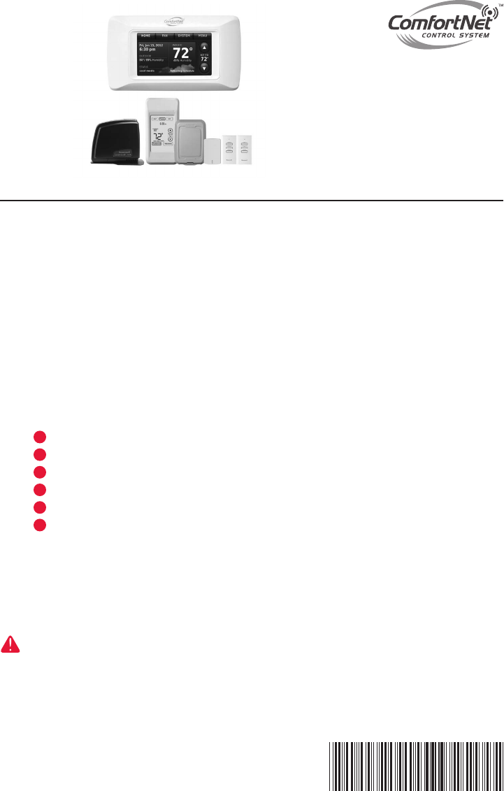
ComfortNet™ CTK03 Communicating Thermostat
With wireless accessories
System
Installation
Guide
Modulating control for up to 4 Heat/2 Cool communicating heat pump systems or up
to 3 Heat/2 Cool communicating gas heat, electric cooling systems for residential and
commercial applications.
Installation guide for:
Quick start guide
• ComfortNetCTK03Communicating
Thermostat
• PortableComfortControl
• WirelessOutdoorSensor
• WirelessIndoorSensor
• RedLINK™InternetGateway
• Entry/ExitRemote
• VentBoostRemote
1 Install thermostat ..........................................................page 4
2 Power optional accessories ...................................................7
3 Setup thermostat ................................................................... 8
4 Link optional accessories ......................................................9
5 Mount optional accessories ................................................. 11
6 Installer options ...................................................................12
ComfortNet™ User Menu .................................................... 13
Wiring guides .......................................................................19
Key features .................................................................... 20-26
Device replacement and specifications ..........................26-27
DISCONNECT POWER BEFORE INSTALLATION. Can cause electrical shock or equipment damage.
MERCURY NOTICE: If this product is replacing a control that contains mercury in a sealed tube, do not place the old control
in the trash. Contact the Thermostat Recycling Corporation at www.thermostat-recycle.org or 800-238-8192 for information on how
and where to properly and safely dispose of your old thermostat.
Must be installed by a trained, experienced technician. Read these instructions carefully. Failure to follow
these instructions can damage the product or cause a hazardous condition.
69-2688-01
I/O-CHTSTAT03

System Installation Guide
2
69-2688—01 I/O-CHTSTAT03
The ComfortNet advantage
ThepremiumHoneywellComfortNet™controlsystemiseasytouse,energy-
efficient,reliableandensuresthesystemissetupproperly.Advancedoperating
algorithmsbuiltintothecontroldeliversefficientequipmentoperationwhilepro-
vidingoptimalcomfort.TheHoneywellComfortNetCommunicatingthermostat
isdesignedtoregulateandcommunicatewiththecentralheatingandcooling
equipmentandhastheabilitytoshareinformationsotheuserwillenjoyefficient,
economical comfort throughout the home.
RedLINK™ Compatible
IncreaseyourcontentandprofitperjobbyincludingHoneywellRedLINK™
accessoriesthatmeetyourcustomerscomfortandconvenienceneeds.RedLINK
accessoriesincludetheWirelessOutdoorSensor,PortableComfortControl
(PCC),RedLINKInternetGateway,WirelessIndoorSensor,TrueSTEAM™humidi-
fierwithWirelessAdapter,VentBoostRemoteandEntry/ExitRemote.
Customizable Service Reminders
Setupto10servicereminders.Choosefromthepre-setoptionsorcustomize
yourown.Remindersbasedondate,outdoortemperatureoradrycontactinput
willalertcustomerswithinstructionstocontactyouforassistance.
User Interactions Log
Theinteractionlogstoreshistoryofthermostatsettingchangesincludingtem-
perature,systemandinstallersetup.Youcanusetheinteractionlogtosavetime
bydeterminingiftheissueisasystemerrororanaccidentalusererror.
Configurable for Residential and Light Commercial Applications
OnethermostatdoesitalltomeettheneedsofResidentialandLightCommercial
applications.SimplyselectResidentialorCommercialduringtheinstallersetup.
IfCommercialisselected,thethermostatwillusecommerciallanguage,meet
buildingcodesandoffer365dayholidayscheduling.
USB Port for Quick Installer Setup
SavetimebyusingaUSBsticktouploadinstallersettingsandservicereminders
in one simple step.
Selectable Sensors
WhenpairedwithaWirelessIndoorSensor(s)youhavetheabilitytochoose
whichsensor(s)tousefortemperature,humidificationanddehumidification.They
canbeusedincombinationfortemperatureaveraging—orindividually—tocondi-
tionhumiditylevelsinseparatespaces.
CTK03 ComfortNet™ Communicating Thermostat
3I/O-CHTSTAT03 69-2688—01
Installation
Thisbookletcontainsinstallationinstructionsandinformationonthethermostat
andwirelessaccessories.Separateinstallationinstructionsforthefurnaceor
airhandlerandoutdoorACcondensingunitorheatpumpareprovidedwiththe
appropriateequipment.Thisthermostatisdesignedexclusivelyforusewiththe
ComfortNetcommunicatingsystem.
Valid System Configurations
Thiscontrolmayonlybeusedwithcertainsystemconfigurations.Validsystem
configurationsforwhichthiscontrolcanbeusedare:
• AcommunicatingairhandlermatchedwithacommunicatingoutdoorAC
condensing unit.
• Acommunicatingairhandlermatchedwithacommunicatingoutdoorheat
pump unit.
• AcommunicatingfurnacematchedwithacommunicatingoutdoorAC
condensing unit.
• Acommunicatingfurnacematchedwithacommunicatingoutdoorheat
pump unit.
• Acommunicatingfurnacematchedwithanon-communicatingsinglestage
ACcondensingunit.
Installing Thermostat
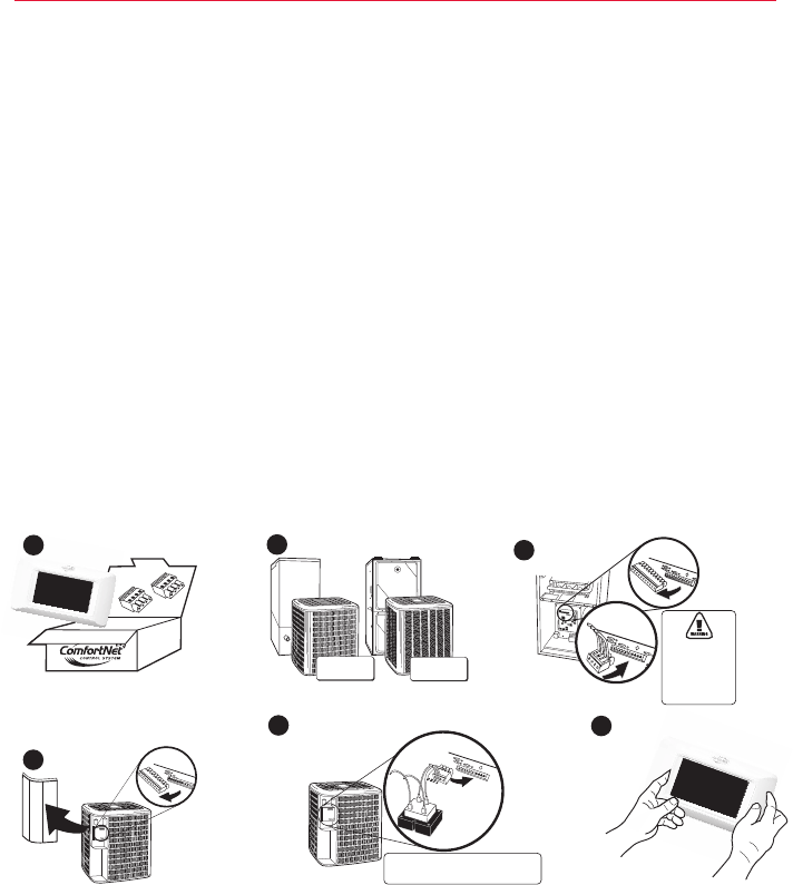
1. RemoveandinventoryallComfortNetcomponents.TheboxcontainstheComfortNetCTK03
communicatingthermostat,lithiumcoincellbattery,wallmountingscrewsandanchors,sys-
teminstallationguide,operatingmanual,AT120A1004transformerwithmountinghardware
andawiringsetthatincludestwoterminalblocksandwires.
2. Carefullyseparatethethermostatbodyfromthethermostatbase.
3. Placebaseatinstallationlocationandmarkmountingholelocationsonwallusingbaseasa
template.
4. Drill mounting holes.
5. Attachbasefirmlytowallusingtwomountingscrews.Levelingisforappearanceonlyand
willnotaffectthermostatoperation.
6. Connectwirestoterminalblockonbase.
7. 18AWGsolidwireisrecommended.
8. Pushexcesswireintowallandplugholewithafireresistantmaterial(suchasfiberglass
insulation)topreventdraftsfromaffectingthermostatoperation.
9. Insertcoincellbatteryinthebackofthethermostat.
10. Carefullylineupthethermostatwiththebaseandsnapintoplace.
REMOVE AND INVENTORY ALL
COMFORTNET™ COMPONENTS
REMOVE OUTDOOR UNIT
COVER AND 7-PIN
CONNECTOR
NOTE: CONTAINS THE CTK03 THERMOSTAT, LITHIUM COIN CELL BATTERY,
WALL MOUNTING SCREWS AND ANCHORS, SYSTEM INSTALLATION GUIDE,
OPERATING MANUAL, AT120A1004 TRANSFORMER WITH MOUNTING
HARDWARE AND A WIRING SET THAT INCLUDES TWO TERMINAL
BLOCKS AND WIRES.
P/N F0430675005
INSTALL HVAC COMPONENTS
GAS
FURNACE
AIR
HANDLER
TERMINALS 1 & 2 ARE
COMMUNICATIONS
WIRES. THEY SHOULD
NEVER BE CONNECTED
TO THE 24 VAC R&C
POWER SUPPLY
TERMINALS.
CONNECT 4-WIRES
FROM STAT AND 2
OR 4 WIRES FROM
OUTDOOR UNIT
P/N F0430679005
P/N F0430673005
CONNECT TO THE OUTDOOR UNIT
2-WIRE/TRANSFORMER
CONNECTION
LOW (24 VAC)
VOLTAGE
HIGH
VOLTAGE
TRANSFORMER LOW
VOLTAGE CONNECTED
TO R AND C
TERMINALS
CONNECT 2-WIRES TO
INDOOR UNIT
CONNECT HIGH VOLTAGE TRANSFORMER LEADS TO L1
AND L2 MALE SPADE TERMINALS ON CIRCUIT BOARD.
DO NOT CONNECT R AND C BETWEEN THE INDOOR UNIT
AND OUTDOOR UNIT. SEE PAGE 5.
TRANSFORMER
(AT120A1004)
INSTALL THERMOSTAT ON INTERIOR WALL
NOTE: THERMOSTAT WILL
AUTOMATICALLY CONFIGURE
TO THE SYSTEM ONCE HIGH
VOLTAGE POWER IS
APPLIED TO THE
INDOOR AND
OUTDOOR
EQUIPMENT.
M33174
1REMOVE 9-PIN CONNECTOR
FROM FURNACE OR AIR
HANDLER CONTROL
23
4
56
AIR CONDITIONER
OR HEAT PUMP
AIR CONDITIONER
OR HEAT PUMP
System Installation Guide
4
69-2688—01 I/O-CHTSTAT03
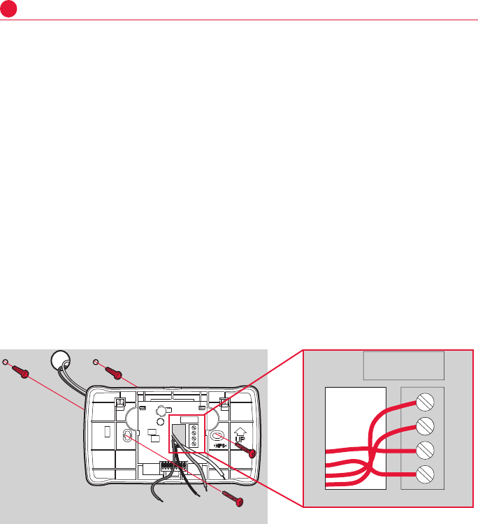
Install thermostat
1
Thermostat Mounting
Mountthethermostatapproximately5feetfromtheflooronaninteriorwallusing
theincludedscrewsandanchors.Drill3/16"holesfordrywalland7/32"holesfor
plaster.Donotinstallthethermostatwhereitcanbeaffectedby:
• Draftsordeadspotsbehinddoorsandincorners.
• Hotorcoldairfromducts.
• Radiantheatfromsunorappliances.
• Concealedpipesandchimneys.
• Unheated(uncooled)areassuchasanoutsidewall.
Terminal Functions:
1-Data1
2-Data2
R-24voltpower
C-24voltcommon
Wire Gauge:
18gaugewireisrecommended.MaximumwiredistancebetweentheComfortNet
thermostatandtheIFCshouldnotexceed100feetusing18gaugewire.
MCR29241
MCR33170
1
2
R
C
MCR33171
1
2
R
C
CTK03 ComfortNet™ Communicating Thermostat
5I/O-CHTSTAT03 69-2688—01
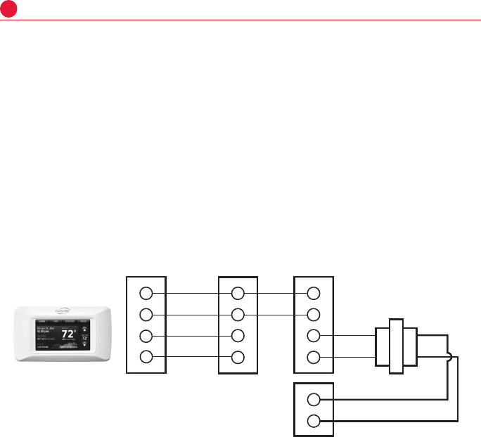
Install thermostat
1
Wiring Thermostat, Indoor Unit and Outdoor Unit
Wire Thermostat to Indoor Unit
Connect1,2,RandCfromthethermostatto1,2,RandCattheIndoorUnit.
Wire Outdoor Unit
Connectwires1and2fromtheIndoorUnitto1and2attheOutdoorUnit.Install
thetransformerprovidedandconnecttoRandCattheOutdoorUnit.DoNOT
connectRandCbetweentheIndoorUnitandOutdoorUnit.Seebelow.
Note:DIPswitch#13ontheequipmentneedstobesettoOFF.Defaultsettingis
OFF.
CTK03
INDOOR
BOARD TE RMINAL
CONNECTIONS
R
C
1
2
24VAC (HOT)
24VAC
(COMMON)
DATA 1
DATA 2
L1
L2
24VAC 230V
OUTDOOR
BOARD TE RMINAL
CONNECTIONS
OUTDOOR
TRANSFORMER
R
C
1
2
R
C
1
2
M33168
System Installation Guide
6
69-2688—01 I/O-CHTSTAT03
M32940
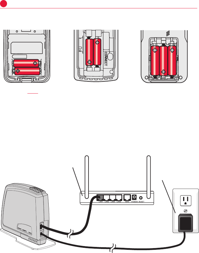
[If no wireless accessories are used, skip to Section 3.]
Portable Comfort Control
Install 2 fresh AAA alkaline batteries Install 3 fresh AA alkaline batteries
Outdoor air sensor Indoor air sensor
Install 2 fresh AA lithium batteries
Power optional accessories
2
TheHoneywellRedLINKInternetGatewaygivesyourcustomersremoteaccess
tohomeclimate-controlsystemsfromanylocationwithInternetaccess.
UsingaWebbrowser,userscanreviewandadjustindoortemperature,
systemmodeandothersettings.TheGatewaycanalsosendalertstoasmany
as6emailaddressesifaproblemoccurs.
RedLINK™ Internet Gateway
Connect power cord to
an electrical outlet not
controlled by a wall switch
Connect RedLINK Gateway to a
router or modem with Ethernet
cable (RJ45).
MCR32937 MCR32938 MCR32939
CTK03 ComfortNet™ Communicating Thermostat
7I/O-CHTSTAT03 69-2688—01
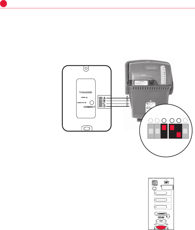
Power optional accessories
2
TrueSTEAM
ConnecttheABCDterminalsbetweenTrueSTEAMandtheTHM4000Wireless
Adapter.
AdjusttheDIPSwitchesonTrueSTEAMasfollowswhenusingtheWireless
Adapter:
DIP3:UP
DIP4:UP
DIP5:DOWN THM4000R1000
Tr ueSTEAM
MCR31476
6
543
2
ON
OFF
1
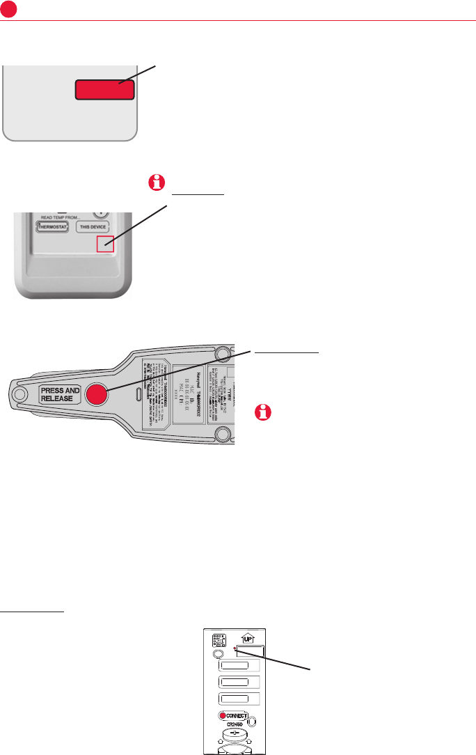
Entry/Exit Remote or Vent Boost Remote
1 Removethecover.
2 InserttheCR2450coincellbattery(included)
intotheslotatthebottomoftheremote.See
polaritymarkingontheremote.
3 TheLEDwillbrieflyflashgreen.Ifitflashesred,
batteryisnotgood.
MCR33269
System Installation Guide
8
69-2688—01 I/O-CHTSTAT03
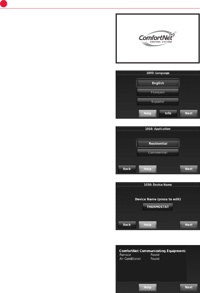
Setup thermostat
3
Initial Power Up
1 TurnonACpowertothesystem.
2 SelectLanguage.PressNext.
3 SelectApplication(Residentialor
Commercial).PressNext.
Thethermostatwillautomaticallyiden-
tifytheComfortNetcommunicating
equipmentinstalledandthenyouwill
bepromptedtoaddRedLINKacces-
sories(page9)andsetuptheInstaller
Options(page12).
4 EnteraDeviceName.PressNext.
CTK03 ComfortNet™ Communicating Thermostat
9I/O-CHTSTAT03 69-2688—01
MCR32935
MCR32934
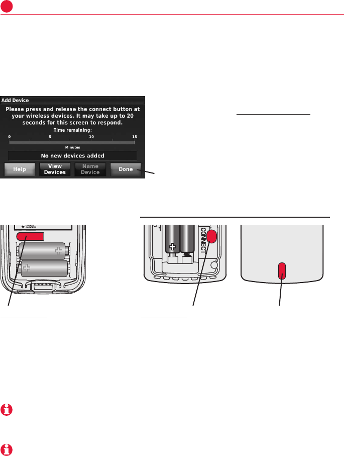
WhiletheAddDevicescreenisdisplayed
on the thermostat, press and release the
CONNECTbuttononeachwirelessdevice,as
describedbelow.Accessoriesneedtobeat
least2feetawayfromthethermostatduring
thelinkingprocess.
Ifyouneedtoreturntothe"AddDevice"screentoadddeviceslater,pressMENU
andscrolldowntopressINSTALLER OPTIONS.Enterthedatecode(password)
whenprompted.Thedatecodeisprintedonthebackofthethermostat;orpress
MENU > EQUIPMENT STATUStofindthedatecode.Afteryouenterthepassword,
scrolldowntopressWIRELESS DEVICE MANAGER and then select ADD DEVICE.
MCR28847A
Link optional accessories to wireless network
4
Wireless outdoor sensor Wireless indoor sensor
Press and release CONNECT. After
a short delay the thermostat will
display "Wireless Outdoor Sensor
added" on the Add Device screen.
Press and release CONNECT.
After a short delay, the status light
will glow green for 15 seconds.
If the status light turns red,
the sensor did not link with the
thermostat.
In normal operation, this light
remains off. If it begins flashing
red, batteries are low (power will
be depleted after 2-3 weeks).
Press DONE after all devices have been linked
When power is interrupted, the equipment and the RedLINK accessories will automatically restore
communication after power resumes.
If you have both a wired and wireless outdoor sensor installed, the thermostat displays the reading
from the wireless outdoor sensor.
System Installation Guide
10
69-2688—01 I/O-CHTSTAT03
Entry/Exit Remote or Vent Boost Remote
Press and release CONNECT button.
TrueSTEAM
Press and release the CONNECT button on the THM4000 Wireless Adapter. After a short delay, the CONNECTED status light will glow
steady green..
Link optional accessories to wireless network
4
MCR32943
RedLINK Internet Gateway
Press and release the button on the bottom of the Internet
Gateway. After a short delay, the RedLINK status light will glow
steady green.
The Internet Gateway must be registered online before
use at www.mytotalconnectcomfort.com. Enter the MAC
ID and MAC CRC numbers located on the bottom of
the Internet Gateway. For additional information, see
instructions provided with the device.
MCR32942
CONNECT
WIRELESS SETUP
Portable Comfort Control
The linking procedure will time out if there is no keypress for 30 minutes. To begin again,
press and hold in the lower right corner of the screen until the display changes (about 3
seconds).
Press CONNECT on the Portable Comfort Control display screen. Press DONE when the
screen displays "Connected." Press NO at the next screen to save and exit. (Or press
YES to link another thermostat.)
Error messages:
E1 29 Incompatible device cannot be connected.
E1 34 Low RF signal. Move device to a different location and try again.
E1 38 Make sure the thermostat is in Wireless Setup mode,
and the Portable Comfort Control is at least 2 feet away (600 mm).
MCR33096
After a short delay, the status light will glow
green for 15 seconds. If the status light
turns red, the remote did not link with the
thermostat for the connection process.
CTK03 ComfortNet™ Communicating Thermostat
11 I/O-CHTSTAT03 69-2688—01
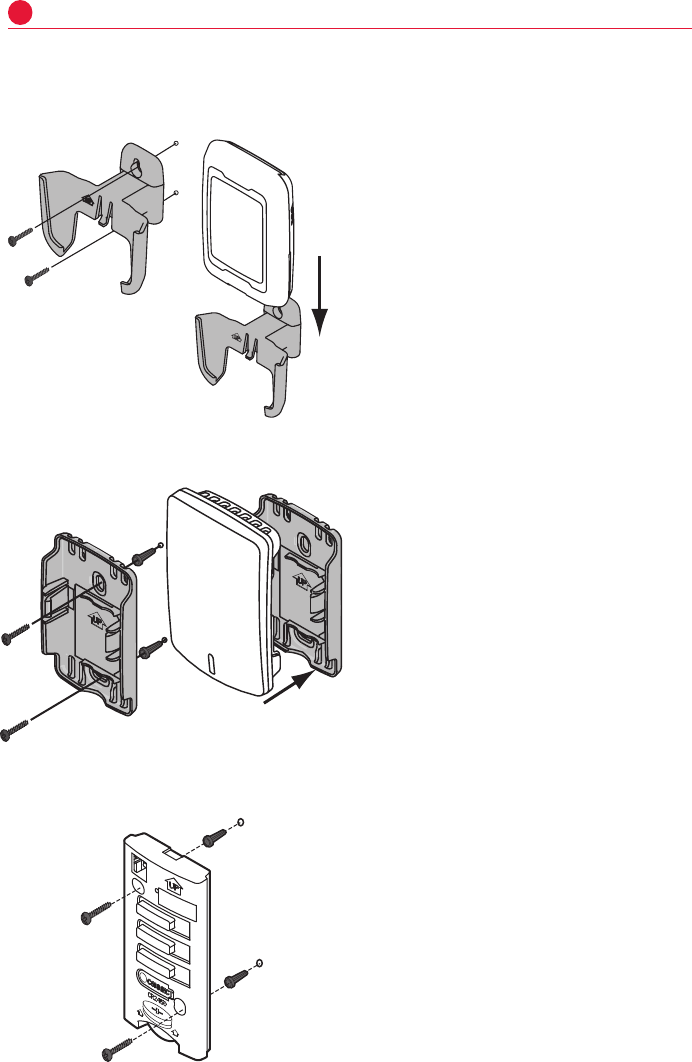
Mount optional accessories
1 Mountthesensoronavertical
exteriorwall,atleast6inchesbelow
anyoverhang.Choosealocation
protected from direct sunlight.
2 Placesensorsecurelyinbracket,
facingawayfromwall.
5
M28491
M28849A
[If no sensors are used, skip to Section 6.]
To install outdoor air sensor
To install indoor air sensor
To install Entry/Exit Remote or Vent Boost Remote
1 Removethewallplateandmountit4
to6feetabovetheflooronaninterior
wall.Drill3/16-inchholesfordrywall,
7/32-inchforplaster.
2 Attachsensorsecurelytowallplateas
shown.
Mounting the remote is optional.
1 Removethefrontcoverfromthe
remote.
2 Useprovidedscrewsandwall
anchors to fasten the remote to the
wall.Drill3/16-inchholesfordrywall,
7/32-inchforplaster.
3 Replacethecoverontheremote.
M32936A
M33095
Do not install the indoor air sensor where it can be affected by:
• Draftsordeadspotsbehinddoorsandincorners.
• Hotorcoldairfromducts.
• Radiantheatfromsunorappliances.
• Concealedpipesandchimneys.
• Unheated(uncooled)areassuchasanoutsidewall
System Installation Guide
12
69-2688—01 I/O-CHTSTAT03
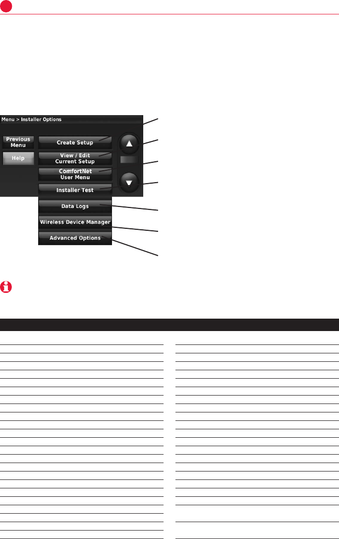
Installer options (ISU)
6
Create Setup: Press CREATE SETUP to set all system settings one
by one.
View/Edit Current Setup: Press VIEW/EDIT CURRENT SETUP to
select a specific function and make quick changes.
ComfortNet User Menu: Press COMFORTNET USER MENU to view
equipment information.
Installer Test: Press INSTALLER TEST to quickly determine if the
heat, cool, fan and thermostat are operating properly. Minimum off
timers are ignored during the test.
Data Logs: Press DATA LOGStoviewtheAlertsLogandUser
Interactions Log.
Wireless Device Manager: Press WIRELESS DEVICE MANAGER
to add or remove wireless accessories.
Advanced Options: Press ADVANCED OPTIONS to setup the
thermostatusingaUSBdeviceortorestorethethermostattothe
factory default settings.
TIP:YoucanusethethermostatUSBporttodownloadallsystemconfigurationandinstalleroptions,includingyourcompany
name and contact information. You can upload this data to each thermostat you install, to save time.
Tosetupthethermostat,pressMENUandscrolldowntopressINSTALLER OPTIONS.
Enterthedatecode(password)whenprompted.Thedatecodeisprintedonthe
backofthethermostat;orpressMENU > EQUIPMENT STATUS to find the date code.
Afteryouenterthepassword,pressCREATE SETUP to setup the thermostat.
Abriefsummaryofinstalleroptionsfollows.Youcandownloadacompletelistof
alloptionsathttp://customer.honeywell.com.
1000 Language B
1010 Residential/Commercial B
1030 Device Name B
1030 Device Name on Home Screen C
1040 Programmable/Non-programmable B
1050 Fahrenheit/Celsius B
1060 Outdoor Air Sensor B
2000 Heating System Type B
2010 Heating Equipment Type B
2070 Heat Stages B
2070 Cool/Compressor Stages B
2070 BackupHeatStages B
2180 BackupHeatType B
3000 Manual/Auto Changeover B
3000 Auto Changeover Deadband B
3010 Temperature Control Options B
3020 Finish With High Cool Stage B
3021 Finish With High Heat Stage B
3030 Staging Control - Cool Differentials B
3050-3060 Staging Control - Heat Differentials B
3090 StagingControl-BackupHeatDifferentials B
3110 BackupHeatUpstageTimer B
3120 Outdoor Compressor Lockout B
3120 OutdoorBackupHeatLockout B
3140 Cool/Compressor Cycles Per Hour B
3150 Heat Cycles Per Hour B
3160 BackupHeatCyclesPerHour B
3170-3190 Cooling Derivative, Integral, Throttling range C
3200-3220 Heating Derivative, Integral, Throttling range C
3240 Minimum Compressor Off Time B
3260 Extended Fan Run Time in Cool B
3260 Extended Fan Run Time in Heat B
4000 Number of Schedule Periods B
4010 Pre-occupancy Purge Duration C
4020 Override: Standard or Initiate Occupancy C
4030 Override Duration C
4050 Minimum Recovery Settings - Heat C
4060 Maximum Recovery Settings - Heat C
4070 Minimum Recovery Settings - Cool C
4080 Maximum Recovery Settings - Cool C
4090 Adaptive Intelligent Recovery R
4100 Minimum Cool Setpoint B
4100 Maximum Heat Setpoint B
4110 Keypad Lockout B
4120 Entry/Exit Remote -
Home/Occupied Cool Setpoint B
4120 Entry/Exit Remote -
Home/Occupied Heat Setpoint B
ISU Function ISU Function
R: Residential C: Commercial B:Both

CTK03 ComfortNet™ Communicating Thermostat
13 I/O-CHTSTAT03 69-2688—01
ComfortNet User Menu
PressMENU > INSTALLER OPTIONS > COMFORTNET USER MENU
AdditionalequipmentinformationisfoundintheComfortNetUserMenu.
PressMENUandscrolldowntopressINSTALLER OPTIONS.Enterthedatecode
(password)whenprompted.Thedatecodeisprintedonthebackofthe
thermostat;orpressMENU > EQUIPMENT
STATUS to find the date code.
Afteryouenterthepassword,press
COMFORTNET USER MENU and then select
theequipmenttype(furnace,airhandler,
airconditioner,heatpump)toviewthe
specifications.
Eachequipmenttypeisdividedinto
categorieswhichinclude:
4130 Entry/Exit Remote -
Away/UnoccupiedCoolSetpoint B
4130 Entry/Exit Remote -
Away/UnoccupiedHeatSetpoint B
4140 Entry/Exit Remote -
Vacation/Holiday Cool Setpoint B
4140 Entry/Exit Remote -
Vacation/Holiday Heat Setpoint B
5040 IndoorSensorsUsedforTemperatureControl B
7000 Filter Type B
7020 Number of Air Filters B
7110 Air Filter Replacement Reminder B
7110 Air Filter 2 Replacement Reminder B
7120 EAC Cell Cleaning Reminder B
7120 EAC Pre-Filter Cleaning Reminder B
7120 EAC Post-Filter Replacement Reminder B
8000 Humidifier Type B
8010 IndoorSensorUsedforHumidificationControl B
8050 Humidification - Window Protection B
8060 System Modes Allowing Humidification B
8070 Humidification Control B
8100 Clean Tank / Water Filter Replacement Reminder B
8100 Humidifier Pad Replacement Reminder B
9000 Dehumidification Equipment B
9010 IndoorSensorUsedforDehumidificationControl B
9020 Humidity Sensor Displayed on the Home Screen B
9070 Dehumidification - Overcooling Limit R
9080 Dehumidification Control C
9090 Dehumidification Minimum On Time C
9100 High Humidity Comfort Reset Setting C
9180 Dehumidification Away Mode B
9190 Dehumidification Away Mode - Fan Control B
9200 Dehumidification Away Mode -
Low Limit Temperature B
9200 Dehumidification Away Mode -
Temperature Setting B
9200 Dehumidification Away Mode -
Dehumidification Setting B
9210 Dehumidifier Filter Replacement Reminder B
10000 Ventilation Type B
10050 Ventilation Control Method B
10090 NumberofBedrooms R
10090 Size of House R
10100 Enter Equipment Ventilation Rate R
10120 Ventilation Percent On Time B
10170 Ventilator Filter Cleaning Reminder B
11000 NumberofUVDevices B
11050 UVBulbReplacementReminder B
11050 UVBulb2ReplacementReminder B
12000 Installer Custom Reminders B
14000 Clock Format B
14010 Daylight Saving Time B
14020 Indoor Temperature Display Offset B
14020 Indoor Humidity Display Offset B
15000-15020 Dealer name, phone, email, website, message B
Installer options (ISU)
6
ISU Function ISU Function
• Configuration: Provides information regarding the setup of the equipment. An example of configuration data is the number
of cooling stages for an AC condensing unit.
• Diagnostics: Provides a fault history of the equipment and allows the installer to clear the fault history.
• Identification: Provides the model and serial number of the equipment and software revision information.
• Sensors: Provides the sensor data of the equipment. In some instances, it may allow the installer to setup or turn off a
sensor.
• Setup: Allows the installer to change the settings of the equipment.
• Status: Provides the current status of the equipment.
Thefollowingpagesprovidesubmenusoftheabovecategoriesforeach
equipmenttypethatmaybeusedwiththisthermostat.
System Installation Guide
14
69-2688—01 I/O-CHTSTAT03
Furnace User Menus
Configuration (CONFIG)
Sub-menu Item Indication (for Display Only; not User Modifiable)
Number of Heat Stages (HT STG) Displays the number of furnace heating stages
Input Rate (BTU/HR) Displays the furnace input rate in kBtu/hr
Motor HP (1/2, 3/4 or 1 MTR HP) Displays the furnace indoor blower motor horse power
Diagnostics (DIAG)
Sub-menu Item
Indication/User Modifiable
Options Comments
Fault 1 (FAULT #1) Most recent furnace fault For display only
Fault 2 (FAULT #2) Next most recent furnace fault For display only
Fault 3 (FAULT #3) Next most recent furnace fault For display only
Fault 4 (FAULT #4) Next most recent furnace fault For display only
Fault 5 (FAULT #5) Next most recent furnace fault For display only
Fault 6 (FAULT #6) Least recent furnace fault For display only
Clear Fault History
(CLEAR)
NO or YES Selecting “YES” clears the fault history
NOTE:Consecutivelyrepeatedfaultsareshownamaximumof3times.
Identification (IDENT)
Sub-menu Item
Indication (for Display Only; not User
Modifiable)
Model Number (MOD NUM) Displays the furnace model number
Serial Number (SER NUM) Displays the furnace serial number (Optional)
Software (SOFTWARE) Displays application software revision

CTK03 ComfortNet™ Communicating Thermostat
15 I/O-CHTSTAT03 69-2688—01
Setup (SETUP)
Sub-menu Item User Modifiable Options Comments
Heat Airflow Trim
(HT TRM)
-10% to +10% in 2% Increments
(Default 0%)
Trims the heating airflow by the
selected amount.
Heat ON Delay
(HT ON)
5, 10, 15, 20, 25, or 30 seconds
(Default 20)
Selects the indoor blower heat on
delay
Heat OFF Delay
(HT OFF)
30, 60, 90, 120, 150, or 180 seconds
(Default 120)
Selects the indoor blower heat off
delay
Heating Air Flow
(HT ADJ)
1, 2, 3, 4 (Default 2) Selects the nominal heating airflow
Status (STATUS)
Sub-menu Item Indication (for Display Only; not User Modifiable)
Mode (MODE) Displays the current furnace operating mode
CFM (CFM) Displays the airflow for the current operating mode
Non-Comm (Non-COMM applies only to a communicating furnace matched with a non-
communicating AC)
Sub-menu Item User Modifiable Options Comments
Cool Airflow (CL
CFM)
18, 24, 30, 36, 42, 48, or
60 (Default 18)
Selects the airflow for the non-communicating
1-stage AC unit
Cool Airflow Trim
(CL TRM)
-10% to +10% in 2%
Increments (Default 0%)
Selects the airflow trim amount for the
noncommunicating 1-stage AC unit
Cool Airflow
Profile (CL PRFL)
A, B, C, or D (Default A) Selects the airflow profile for the
noncommunicating 1-stage AC unit
Cool ON Delay
(CL ON)
5, 10, 20, or 30 seconds
(Default 5)
Selects the indoor blower on delay for the
noncommunicating 1-stage AC unit
Cool OFF Delay
(CL OFF)
30, 60, 90, or 120 seconds
(Default 30)
Selects the indoor blower off delay for the
noncommunicating 1-stage AC unit
System Installation Guide
16
69-2688—01 I/O-CHTSTAT03
Air Handler User Menus
Configuration (CONFIG)
Sub-menu Item Indication (for Display Only; not User Modifiable)
Electric Heat Size (HTR KW) Displays the size, in kW, of the selected electric heaters
Motor HP (1/2, 3/4 or 1 MTR HP) Displays the furnace indoor blower motor horse power
Heat ON Delay (HT ON) Displays the electric heat indoor blower on delay
Heat OFF Delay (HT OFF) Displays the electric heat indoor blower off delay
Diagnostics (DIAG)
Sub-menu Item Indication/User Modifiable Options Comments
Fault 1 (FAULT #1) Most recent air handler fault For display only
Fault 2 (FAULT #2) Next most recent air handler fault For display only
Fault 3 (FAULT #3) Next most recent air handler fault For display only
Fault 4 (FAULT #4) Next most recent air handler fault For display only
Fault 5 (FAULT #5) Next most recent air handler fault For display only
Fault 6 (FAULT #6) Least recent air handler fault For display only
Clear Fault History
(CLEAR)
NO or YES Selecting “YES” clears
the fault history
NOTE:Consecutivelyrepeatedfaultsareshownamaximumof3times.
Identification (IDENT)
Sub-menu Item Indication (for Display Only; not User Modifiable)
Model Number (MOD NUM) Displays the air handler model number
Serial Number (SER NUM) Displays the air handler serial number (Optional)
Software (SOFTWARE) Displays application software revision
Setup (SETUP)
Sub-menu Item User Modifiable Options Comments
Heat Airflow Trim
(HT TRM)
-10% to +10% in 2% Increments
(Default 0%)
Trims the electric heating airflow
by the selected amount.
Status (STATUS)
Sub-menu Item Indication (for Display Only; not User Modifiable)
Mode (MODE) Displays the current air handler operating mode
CFM (CFM) Displays the airflow for the current operating mode

CTK03 ComfortNet™ Communicating Thermostat
17 I/O-CHTSTAT03 69-2688—01
Heat Pump/Air Conditioner User Menus
Configuration (CONFIG)
Sub-menu Item Indication (for Display Only; not User Modifiable)
AC Tonnage (TONS) Displays the air conditioning tonnage; applies to AC and HP.
Number of AC Stages
(CL STG)
Displays the number of air conditioning stages; applies to AC and HP.
Number of HP Stages
(HT STG)
Displays the number of heat pump stages; applies to HP only.
Diagnostics (DIAG)
Sub-menu Item Indication/User Modifiable Options Comments
Fault 1 (FAULT #1) Most recent AC/HP fault For display only
Fault 2 (FAULT #2) Next most recent AC/HP fault For display only
Fault 3 (FAULT #3) Next most recent AC/HP fault For display only
Fault 4 (FAULT #4) Next most recent AC/HP fault For display only
Fault 5 (FAULT #5) Next most recent AC/HP fault For display only
Fault 6 (FAULT #6) Least recent AC/HP fault For display only
Clear Fault History
(CLEAR)
NO or YES Selecting “YES” clears the fault
history
NOTE:Consecutivelyrepeatedfaultsareshownamaximumof3times.
Identification (IDENT)
Sub-menu Item Indication (for Display Only; not User Modifiable)
Model Number (MOD NUM) Displays the air conditioner or heat pump model number
Serial Number (SER NUM) Displays the air conditioner or heat pump serial number
(Optional)
Software (SOFTWARE) Displays application software revision
Sensors (SENSORS)
Sub-menu Item
Indication/User
Modifiable Options Comments
Outdoor Air Temperature
(AIR TMP)
Displays the outdoor air
temperature
Sensor may or may not be available on
an air conditioner. Check air conditioner
instructions for details.
Outdoor Coil Temperature
(COIL TMP)
Displays the outdoor coil
temperature
Applies for heat pump operation.

System Installation Guide
18
69-2688—01 I/O-CHTSTAT03
Status (STATUS)
Sub-menu Item Indication (for Display Only; not User Modifiable)
Mode (MODE) Displays the current air handler operating mode
CFM (CFM) Displays the airflow for the current operating mode
Cool Set-up (SETUP)
Sub-menu
Item User Modifiable
Options Comments
Cool Airflow Trim
(CL TRM)
-10% to +10% in 2%
Increments (Default 0%)
Selects the airflow trim amount; applies to air
conditioner only.
Cool Airflow Profile
(CL PRFL)
A, B, C, or D (Default D) Selects the airflow profile; applies to air
conditioner only.
Cool ON Delay (CL
ON)
5, 10, 20, or 30 seconds
(Default 5)
Selects the indoor blower on delay; applies to
air conditioner only.
Cool OFF Delay (CL
OFF)
30, 60, 90, or 120
seconds (Default 30)
Selects the indoor blower off delay; applies to
air conditioner only.
Dehumidification
Select (DEHUM)
ON or OFF (Default is
OFF)
Selecting “OFF” disables dehumidification;
selecting “ON” enables dehumidification;
applies to air conditioner only.
Heat Set-Up (HT SETUP) Applies to Heat Pump Systems Only
Sub-menu Item User Modifiable Options Comments
Heat Airflow Trim
(HT TRM)
-10% to +10% in 2%
Increments (Default 0%)
Selects the airflow trim amount; applies to heat
pump only.
Heat ON Delay
(HT ON)
5, 10, or 15 seconds
(Default 5-sec.)
Selects the indoor blower on delay; applies to
heat pump only.
Heat OFF Delay
(HT OFF)
30, 50, 70, or 90 seconds
(Default 30-sec.)
Selects the indoor blower off delay; applies to
heat pump only.
Defrost Interval
(DEFROST)
30, 60, 90, or 120 minutes
(Default 30-min.)
Selects the time interval between defrost;
applies to heat pump only.
Compressor
Delay (CMP DLY)
0, 5, 15, or 30 seconds
(Default 30-sec.)
Selects the compressor off time after a
reversing valve shift; applies to heat pump only.
CTK03 ComfortNet™ Communicating Thermostat
19 I/O-CHTSTAT03 69-2688—01
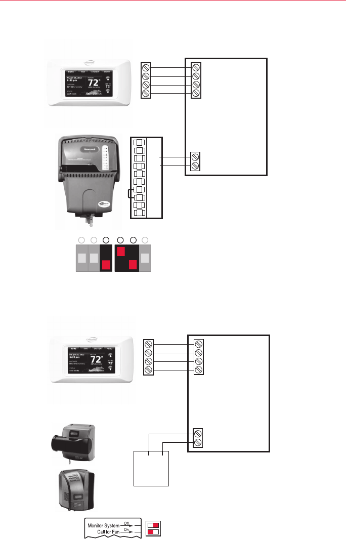
Wiring humidifier to the IFC
Wiring TrueEASE to IFC
Wiring TrueSTEAM to IFC
Tochangeinstallersetup(ISU)information,seepages12-13.
IFC
1
2
R
C
THERMOSTAT
1
2
R
C
HUM
HUM
1. WIRE THERMOSTAT AND TrueSTEAM AS SHOWN.
2. SET THERMOSTAT ISU 8000 TO “STEAM”.
3. SET TrueSTEAM DIP SWITCHES AS SHOWN (3 DOWN, 4 UP, 5 DOWN).
NOTE
FAN INTERLOCK IS HANDLED BY THE COMFORTNET COMMUNICATION.
TrueSTEAM DIP SWITCHES
TRUESTEAM
MCR33172
24 V
24 V
HUM
HUM
C
GT
R
RT
GF
EXT
6
5
43
2
ON
OFF
1
AFS MONITOR RECOMMENDED
IFC
1
2
R
C
THERMOSTAT
1
2
R
C
HUM
HUM
1. WIRE THERMOSTAT AND TrueEASE AS SHOWN.
2. SET THERMOSTAT ISU 8000 TO “BYPASS OR FAN POWERED”.
3. SET TrueEASE DIP SWITCHES AS SHOWN :
• TOP DIP SWITCH – SET TO THE RIGHT
• BOTTOM DIP SWITCH – SET TO THE LEFT
NOTE
FAN INTERLOCK IS HANDLED BY THE COMFORTNET COMMUNICATION.
MCR33173
TrueEASE DIP SWITCHES
BYPASS
HUM
CONTROL
FAN
POWERED
TrueEASE
System Installation Guide
20
69-2688—01 I/O-CHTSTAT03
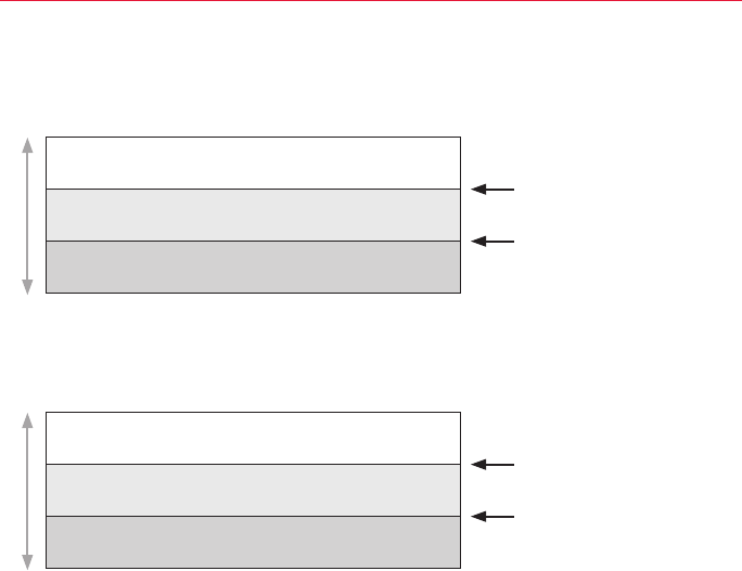
Heat pump with outdoor temperature lockouts
Outdoortemperaturelockoutsareoptional.SeeInstallerSetup
options(ISU3120).
Heat pump only
Heat pump with backup heat as needed *
Backup heat only
Heat pump only
Heat pump or backup heat operates *
Backup heat only
Outdoor temperatureOutdoor temperature
Backup heat lockout
Backup heat lockout
Compressor lockout
Compressor lockout
* NobackupheatunlessindoortemperaturedropstoselectedBackupHeatDifferentialsetting,orBackupHeat
UpstageTimerexpires.Heat pump stays ON when backup heat turns on.
* NobackupheatunlessindoortemperaturedropstoselectedBackupHeatDifferentialsetting,orBackup
HeatUpstageTimerexpires.Heat pump turns OFF when backup heat turns on.
Electric - Backup heat allowed to run with heat pump
Fossil Fuel - Backup heat NOT allowed to run with heat pump

CTK03 ComfortNet™ Communicating Thermostat
21 I/O-CHTSTAT03 69-2688—01
Backup heat differential and upstage timer
Basic and Advanced Temperature Control Options (ISU 3010)
Abackupheatdifferentialandbackupheatupstagetimercanbesetonheat
pumpsystemswithbackupheat.Seeinstallersetupoptions(ISU3090-3110).
Normal operation
WhentheBackup Heat DifferentialissettoComfort,thethermostatusesbackup
heatasneededtokeeptheindoortemperaturewithin1°F(0.5°C)oftheset-
point.
WhentheBackup Heat Differentialissetto2°Forhigher,backupheatisnot
used unless the indoor temperature drops to the Backup Heat Differential setting
or the Backup Heat Upstage Timerexpires,whicheveroccursfirst.Theupstage
timerstartswhenthehigheststageofthepreviousequipmenttypeturnson.
Manual temperature change
WhentheBackup Heat DifferentialissettoComfort,thethermostatusesbackup
heatasneededtokeeptheindoortemperaturewithin1°F(0.5°C)oftheset-
point.
WhentheBackup Heat Differentialissetto2°Forhigher,iftheheatpumpis
makingprogressasexpected,backupheatwillnotbeusedtoreachthenew
setpoint.Settoahighernumbertouselessbackupheat(agreaterdifference
betweenthecurrentindoortemperatureandthenewsetpointisrequiredtoturn
onbackupheat).Seenotesbelow.
Programmed recovery
Iftheheatpumpismakingprogressasexpected,backupheatwillnotbeused
toreachthesetpointofthenextprogramperiod.Backupheatisalways restrict-
edduringaprogrammedrecoverywhentheAdaptiveIntelligentRecoveryfeature
isused.Seenotebelow.
Basic Options:TheInstallerSetupdisplaysbasictemperaturecontroloptions
whichincludeBackupHeatDifferential,BackupHeatUpstageTimerandOutdoor
TemperatureLockouts.Note:OutdoorTemperatureLockoutsonlyapplytoHeat
Pumpapplications.
Advanced Options:TheInstallerSetupdisplaysbothBasicandAdvanced
Options.AdvancedtemperaturecontroloptionsincludeFinishWithHighCool
Stage,FinishWithHighHeatStage,TemperatureDifferentialsettingsbetweenall
stagesandCycleRatesettingsperstage.
During a programmed recovery (or when the temperature setpoint is changed by the user), the thermostat waits to turn on the
backup heat depending on system performance, load conditions and how many degrees the temperature setpoint is changed.
BackupheatwillbeusedONLYwhenthetemperatureisnotrisingquicklyenoughtoreachthesetpointinareasonabletime.
If the backup heat was used in the last 2 hours because the heat pump was not able to maintain the setpoint, the thermostat
may turn on the backup heat earlier when the user raises the setpoint.
Finish With High Heat or Cool Stage - When a multi-stage heating or cooling system is used, this feature keeps the high stage
of the heating or cooling equipment running until the desired setpoint is reached.
System Installation Guide
22
69-2688—01 I/O-CHTSTAT03
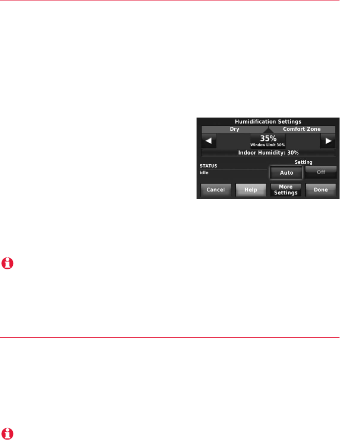
Humidification
Thethermostatreadstheindoorhumiditylevelandallowstheusertoseta
humidificationsettingwithorwithoutwindowprotection.
Window Protection
WindowProtectionlimitstheamountofhumiditytopreventfrostorcondensa-
tiononwindows.WindowProtection(ISU8050)requiresanoutdoorsensor.
Themaximumhumiditylevelthatisallowed("WindowLimit")isdisplayedonthe
HumidificationSettingsscreen.Thethermostatpreventsfrostorcondensation
onwindowsbynotallowingthehumiditytogoabovetheWindowLimitwhenit
iscontrollingthehumidifier.Thishelpsinformtheuserastowhytheirhumidity
settingmightnotbereachedattimes.The
WindowLimitisbasedonthecurrentoutdoor
temperatureandtheuser'swindowprotection
setting.
IfWindowProtectionisturnedOff,thether-
mostatcontrolsthehumidityleveltothe
user'sdesiredhumiditysetting.Frostorcon-
densationmayappearonwindows.
Dehumidification - Residential
Thethermostatreadstheindoorhumiditylevelandallowstheusertosetadehu-
midification setting.
Whensetupfordehumidificationusingthecoolingsystem,anovercoolinglimit
canbesetfrom0Fto3F(ISU9070).Thethermostatusesthecoolingsystem
toreducehumiditybyloweringthetemperatureupto3Fbelowthecurrentcool
setpointuntilthedesiredhumiditylevelisreached.
To see all dehumidification options, press MENU > INSTALLER OPTIONS > VIEW/EDIT CURRENT SETUP >
DEHUMIDIFICATION.
To see all humidification options, press MENU > INSTALLER OPTIONS > VIEW/EDIT CURRENT SETUP >
HUMIDIFICATION.

CTK03 ComfortNet™ Communicating Thermostat
23 I/O-CHTSTAT03 69-2688—01
Dehumidification - Commercial
Thethermostatreadstheindoorhumiditylevelandallowstheusertoseta
dehumidification setting.
Dehumidificationusingthecoolingsystemhasthefollowingmethodsof
dehumidificationcontrol(ISU9080):
Basic:Thisoptionusesthecoolingsystemtoreachthedesiredhumiditylevel.
MinimumOnTimeandHighHumidityComfortResetarenotusedwiththis
method.Thisoptionshouldonlybeusediftheequipmentcanlowerthefan
speed in a call for dehumidification.
Minimum on Time (ISU 9090):Thisoptionensuresthatthecompressorruns
longenoughtoeffectivelyreducehumiditywhenthecoolingequipmentiscycled
on.Thecompressorwillrunfortheminimum"ontime"yousetuntilthedesired
humiditylevelisreached.
High Humidity Comfort Reset (ISU 9100):Thisoptionusesthecoolingsystem
tolowerthetemperatureupto5Fbelowthecurrentcoolsetpointuntilthe
desiredhumidityisreached.Thehighhumiditycomfortrangeisfrom1to5F.
High Humidity Comfort Reset with Minimum On Time (ISU 9090 and
ISU 9100):Thismethodusesbothoptionsabovetoreducehumiditywhile
maintainingacomfortabletemperature.
To see all dehumidification options, press MENU > INSTALLER OPTIONS > VIEW/EDIT CURRENT SETUP >
DEHUMIDIFICATION.
System Installation Guide
24
69-2688—01 I/O-CHTSTAT03
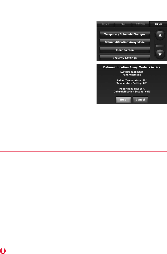
Dehumidification Away Mode
DehumidificationAwayModeprotectsthehomewhenunoccupiedforlong
periodsoftimeduringhotandhumidweatherbymaintainingthedesired
humidity and temperature settings.
TostartDehumidificationAwayMode,press
Menu,thenpressDehumidificationAway
Mode.Thethermostatautomaticallyfollows
settingsthataresetbythedealerduring
installer setup.
PressCanceltoendDehumidificationAway
Mode.
Southern Dehumidification Away
Mode Options: (ISU 9180 to 9200)
• Fan:Auto,OnorCirculate
• LowLimitTemperatureSetting:The
thermostatallowsthecoolingsystem
tolowertheindoorairtotheLowLimit
TemperatureSettingtocontrolhumidity.
• TemperatureSetting:Thetemperature
maintainedwhileDehumidificationAwayModeisactiveandthedesired
humiditylevelissatisfied.
• DehumidificationSetting:ThedesiredhumiditylevelwhileDehumidification
AwayModeisactive.
Ventilation
Ventilation Control Method (ISU 10050)
ThethermostatcancontrolthefantomeeteitherASHRAEorPercentOnTime
settings.IftherequiredventilationhasnotbeenachievedforASHRAEorPercent
OnTimeduringcallsforheatandcool,thethermostatwillforcethefanon.
• ASHRAE:ThethermostatoperatesthefantomeettheASHRAE62.2
ventilationstandardbasedonCFM,numberofbedrooms,andsquare
footageofthehouse.ASHRAE62.2canonlybemetifthefanisrunning.If
thefanisoffforanyreason(setuptoturnOffduringSleepperiod,turned
offbyuseretc.),ASHRAE62.2isnotmetduringthosetimes.
• Percent On Time:Thethermostatoperatesthefanbasedonapercentage
enteredintheinstallersetup(ISU10120).Forexample,ifPercentOnTime
issetto50%,thefanwillrunatrandomtimesduringa1hourperioduntilit
reachesa50%runtime(approximately30minutes).Options10%to100%.
To see all ventilation options, press MENU > INSTALLER OPTIONS > VIEW/EDIT CURRENT SETUP >
VENTILATION.
CTK03 ComfortNet™ Communicating Thermostat
25 I/O-CHTSTAT03 69-2688—01
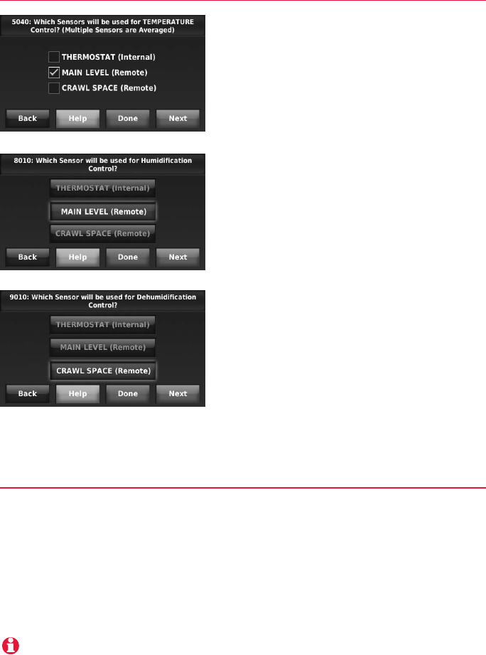
Indoor sensor operation
Wireless indoor sensor
Temperature control
Thethermostatcanbesettorespondtoits
internal temperature sensor, or to an option-
alremoteindoorsensor.Ifmultiplesensors
areused,thethermostatwillrespondtoan
averageoftemperaturesdetectedateach
sensor.
Humidification control
Ifoptionalremoteindoorsensorsare
installed,youcanchoosewhichsensoryou
wanttouseforhumidificationcontrol.You
can use a different sensor for dehumidifica-
tion.
Dehumidification control
Ifoptionalremoteindoorsensorsare
installed,youcanchoosewhichsensor
youwanttousefordehumidificationcon-
trol.Forexample,youcanuseonesensor
for humidification control, and another for
dehumidification.
The thermostat can use up to 6 optional wireless sensors.
Battery level indicators (when batteries are inserted)
• Good: Status light flashes green for 5 seconds.
• Low:Statuslightflashesredfor5seconds.Usefreshbatteries.
Battery level indicators (during use)
• Good: Status light remains off.
• Low:Batterypowerwillbedepletedinabout2months.ThermostatdisplaysLowBatterywarning.Statuslight
remains off.
• Critical:Batterypowerwillbedepletedinabout2–3weeks.Statuslightflashesred.

System Installation Guide
26
69-2688—01 I/O-CHTSTAT03
Alerts Log
MENU > INSTALLER OPTIONS > DATA LOGS > ALERTS LOG
Thethermostatsavesthemostrecent25alerts.Itrecordsthedate,time,alert
status(snoozed,dismissed,recovered),anddiagnosticinformationtohelpyou
identifyandcorrectproblems.
User Interactions Log
MENU > INSTALLER OPTIONS > DATA LOGS > USER INTERACTIONS LOG
Checkthislogtofindoutifaproblemwascausedbyanaccidentalusererror.
Thelogshowsmostchangesmadetothermostatsettings,bytimeanddate,and
describeswhatchangewasmade.
Thethermostatrecordsthemostrecent250changes.Youcanquicklysearch
thembydateandtime,orbyfunction.Thisfeaturecanbeturnedoffifnecessary,
so that no user interactions are recorded.
Examples:
* [date, time] Heattemperaturesetto80°F
* [date, time] SystemmodesettoOff
* [date, time] Installersetupchanged—heatingequipmenttype
Replacing system components
FollowstepsbelowtodisconnectthethermostatandRedLINKaccessories.
To replace a thermostat
AtthePortableComfortControl
1 Pressandholdtheblankspace(orarrowif
present)inthelowerrighthandcornerofthe
screen until the display changes.
2 PressREMOVE, then YES to disconnect from the
old thermostat.
AttheIndoorSensor,Entry/ExitRemote,VentBoostRemote,RedLINKInternet
GatewayorTrueSTEAMWirelessAdapter
1 PressandholdtheCONNECTbuttonontheRedLINKaccessoryuntilthe
statuslightglowsamber(holdforabout10seconds).Thiswilldisconnect
thedevicefromtheoldthermostat.
Re-connectRedLINKaccessories
1 Followthestepsin“Linkoptionalaccessoriestowirelessnetwork”onpage
9.
MCR32958
Press and hold
in lower right
corner of screen

CTK03 ComfortNet™ Communicating Thermostat
27 I/O-CHTSTAT03 69-2688—01
Replacing system components
To remove accessories from a thermostat
Atthethermostat
1 PressMENUandscrolldowntopressINSTALLER OPTIONS.Enterthedatecode
(password)whenprompted.Thedatecodeisprintedonthebackofthe
thermostat;orpressMENU > EQUIPMENT STATUS to find the date code.
2 Afteryouenterthepassword,scrolldowntoselectWIRELESS DEVICE
MANAGER.
3 PressREMOVE DEVICE,thenselectthedeviceyouwanttoremove.
Specifications & replacement parts
Operating Ambient Temperature
Thermostat:32to120°F(0to48.9°C)
Portable Comfort Control: 32to120°F(0to48.9°C)
Wireless Outdoor Sensor:-40to140°F(-40to60°C)
Wireless Indoor Sensor:0to120°F(-17.8to48.9°C)
– ForOptimalBatteryLife:35to114°F(1.7to45.6°C)
RedLINK Internet Gateway:32to120°F(0to48.9°C)
Operating Relative Humidity
Thermostat:5%to90%(non-condensing)
Portable Comfort Control: 5%to90%(non-condensing)
Wireless Outdoor Sensor:0%to100%(condensing)
Wireless Indoor Sensor:5%to90%(non-condensing)
RedLINK Internet Gateway:5%to95%(non-condensing)
Physical Dimensions(height,width,depth)
Thermostat: 3-7/8x6-13/16x1-7/16inches(99x173mmx36mm)
Wireless Outdoor Sensor:5x3-1/2x1-11/16inches(127x89x43mm)
Wireless Indoor Sensor:2-7/8x1-7/8x15/16inches(74x48x24mm)
Portable Comfort Control: 6-1/4x3-1/8x1-5/8inches(158x80x38mm)
RedLINK Internet Gateway:6x4-7/8x2-1/2inches(152x124x64mm)
Electrical Ratings
18to30VAC
Accessories & Replacement Parts
Item Honeywell Part Number
RedLINKInternetGateway THM6000R1002
Entry/ExitRemote REM1000R1003
VentBoostRemote HVC20A1000
PortableComfortControl REM5000R1001
WirelessOutdoorSensor C7089R1013
WirelessIndoorSensor C7189R1004
CoverPlate(coversmarksleftbyoldthermostats) 50028399-001
BatteryPack(Fordemouseonly) THP1000A1007

Regulatory information
FCC Compliance Statement (Part 15.19) (USA only)
This device complies with Part 15 of the FCC Rules. Operation is subject to the following two conditions:
1 This device may not cause harmful interference, and
2 This device must accept any interference received, including interference that may cause undesired operation.
FCC Warning (Part 15.21) (USA only)
Changes or modifications not expressly approved by the party responsible for compliance could void the user’s authority to operate the
equipment.
FCC Interference Statement (Part 15.105 (b)) (USA only)
ThisequipmenthasbeentestedandfoundtocomplywiththelimitsforaClassBdigitaldevice,pursuanttoPart15oftheFCCRules.
These limits are designed to provide reasonable protection against harmful interference in a residential installation. This equipment
generates uses and can radiate radio frequency energy and, if not installed and used in accordance with the instructions, may cause
harmful interference to radio communications. However, there is no guarantee that interference will not occur in a particular installation.
If this equipment does cause harmful interference to radio or television reception, which can be determined by turning the equipment off
and on, the user is encouraged to try to correct the interference by one of the following measures:
• Reorientorrelocatethereceivingantenna.
• Increasetheseparationbetweentheequipmentandreceiver.
• Connecttheequipmentintoanoutletonacircuitdifferentfromthattowhichthereceiverisconnected.
• Consultthedealeroranexperiencedradio/TVtechnicianforhelp.
Thermostats and outdoor sensor
To comply with FCC and Industry Canada RF exposure limits for general population/ uncontrolled exposure, the antenna(s) used for
these transmitters must be installed to provide a separation distance of at least 20 cm from all persons and must not be co-located or
operating in conjunction with any other antenna or transmitter.
Portable Comfort Control
This portable transmitter with its antenna complies with FCC and Industry Canada RF exposure limits for general population/
uncontrolled exposure. This device must not be co-located or operating in conjunction with any other antenna or transmitter.
Section 7.1.2 of RSS-GEN
UnderIndustryCanadaregulations,thisradiotransmittermayonlyoperateusinganantennaoftypeandmaximum(orlesser)
gain approved for the transmitter by Industry Canada. To reduce potential radio interference to other users, the antenna type and
its gain should be so chosen that the equivalent isotropically radiated power (e.i.r.p.) is not more than that necessary for successful
communication.
Section 7.1.3 of RSS-GEN
Operation is subject to the following two conditions:
1 this device may not cause interference, and
2 this device must accept any interference, including interference that may cause undesired operation of the device.
Honeywell International Inc.
1985 Douglas Drive North
Golden Valley, MN 55422
http://customer.honeywell.com
Goodman Manufacturing Co., LP
Suite 500
5151 San Felipe
Houston, TX 77056
® U.S. Registered Trademark. © 2012 Honeywell International Inc.
69-2688—01 M.S. 01-12
I/O-CHTSTAT03
Printed in U.S.A.
Need Help?
Forassistancepleasevisitwww.ComfortNet1.com,orcalltoll-free:(888)593-9988