Adt Security Services Unimode 9600 Users Manual Adtuni9600_combenglC0
51336 51336 AlarmHow.net Library
9600 to the manual c714076d-578e-4935-baa5-43f0e6098e67
2015-02-02
: Adt-Security-Services Adt-Security-Services-Unimode-9600-Users-Manual-413053 adt-security-services-unimode-9600-users-manual-413053 adt-security-services pdf
Open the PDF directly: View PDF ![]() .
.
Page Count: 148 [warning: Documents this large are best viewed by clicking the View PDF Link!]
U n i m o d e 9 6 0 0
Addressable Fire Alarm Control Panel
Programming, Installation, Maintenance
and Operating Instruction Manual
ADT Security Services, Inc.
One Town Center Road
Boca Raton, FL 33431
Phone: (561) 988-3600
FAX: (561) 988-3675
IMPORTANT! The Signaling Line Circuit Wiring Manual Document #51520 must be referenced in
addition to this manual when installing or servicing the Fire Alarm Control Panel.
P/N 51336:C ECN 01-535
Document #51336
11/06/01 Revision: C
LimWarLg.p65 01/10/2000
An automatic fire alarm system–typically made up of smoke
detectors, heat detectors, manual pull stations, audible warn-
ing devices, and a fire alarm control with remote notification
capability–can provide early warning of a developing fire.
Such a system, however, does not assure protection against
property damage or loss of life resulting from a fire.
The Manufacturer recommends that smoke and/or heat detec-
tors be located throughout a protected premise following the
recommendations of the current edition of the National Fire
Protection Association Standard 72 (NFPA 72),
manufacturer's recommendations, State and local codes, and
the recommendations contained in the Guide for Proper Use
of System Smoke Detectors, which is made available at no
charge to all installing dealers. A study by the Federal Emer-
gency Management Agency (an agency of the United States
government) indicated that smoke detectors may not go off in
as many as 35% of all fires. While fire alarm systems are de-
signed to provide early warning against fire, they do not guar-
antee warning or protection against fire. A fire alarm system
may not provide timely or adequate warning, or simply may not
function, for a variety of reasons:
Smoke detectors may not sense fire where smoke cannot
reach the detectors such as in chimneys, in or behind walls, on
roofs, or on the other side of closed doors. Smoke detectors
also may not sense a fire on another level or floor of a build-
ing. A second-floor detector, for example, may not sense a
first-floor or basement fire.
Particles of combustion or "smoke" from a developing fire
may not reach the sensing chambers of smoke detectors be-
cause:
• Barriers such as closed or partially closed doors, walls, or
chimneys may inhibit particle or smoke flow.
• Smoke particles may become "cold," stratify, and not reach
the ceiling or upper walls where detectors are located.
• Smoke particles may be blown away from detectors by air
outlets.
• Smoke particles may be drawn into air returns before
reaching the detector.
The amount of "smoke" present may be insufficient to alarm
smoke detectors. Smoke detectors are designed to alarm at
various levels of smoke density. If such density levels are not
created by a developing fire at the location of detectors, the
detectors will not go into alarm.
Smoke detectors, even when working properly, have sensing
limitations. Detectors that have photoelectronic sensing
chambers tend to detect smoldering fires better than flaming
fires, which have little visible smoke. Detectors that have ion-
izing-type sensing chambers tend to detect fast-flaming fires
better than smoldering fires. Because fires develop in differ-
ent ways and are often unpredictable in their growth, neither
type of detector is necessarily best and a given type of detec-
tor may not provide adequate warning of a fire.
Smoke detectors cannot be expected to provide adequate
warning of fires caused by arson, children playing with
matches (especially in bedrooms), smoking in bed, and violent
explosions (caused by escaping gas, improper storage of
flammable materials, etc.).
Heat detectors do not sense particles of combustion and
alarm only when heat on their sensors increases at a prede-
termined rate or reaches a predetermined level. Rate-of-rise
heat detectors may be subject to reduced sensitivity over time.
For this reason, the rate-of-rise feature of each detector
should be tested at least once per year by a qualified fire pro-
tection specialist.
Heat detectors are designed to protect
property, not life.
IMPORTANT!
Smoke detectors must be installed in the
same room as the control panel and in rooms used by the sys-
tem for the connection of alarm transmission wiring, communi-
cations, signaling, and/or power.
If detectors are not so lo-
cated, a developing fire may damage the alarm system, crip-
pling its ability to report a fire.
Audible warning devices such as bells may not alert people
if these devices are located on the other side of closed or
partly open doors or are located on another floor of a building.
Any warning device may fail to alert people with a disability or
those who have recently consumed drugs, alcohol or medica-
tion. Please note that:
•Strobes can, under certain circumstances, cause seizures
in people with conditions such as epilepsy.
•Studies have shown that certain people, even when they
hear a fire alarm signal, do not respond or comprehend the
meaning of the signal. It is the property owner's responsibil-
ity to conduct fire drills and other training exercise to make
people aware of fire alarm signals and instruct them on the
proper reaction to alarm signals.
•In rare instances, the sounding of a warning device can
cause temporary or permanent hearing loss.
A fire alarm system will not operate without any electrical
power. If AC power fails, the system will operate from standby
batteries only for a specified time and only if the batteries
have been properly maintained and replaced regularly.
Equipment used in the system may not be technically com-
patible with the control. It is essential to use only equipment
listed for service with your control panel.
Telephone lines needed to transmit alarm signals from a
premise to a central monitoring station may be out of service
or temporarily disabled. For added protection against tele-
phone line failure, backup radio transmission systems are rec-
ommended.
The most common cause of fire alarm malfunction is inade-
quate maintenance. To keep the entire fire alarm system in
excellent working order, ongoing maintenance is required per
the manufacturer's recommendations, and UL and NFPA stan-
dards. At a minimum, the requirements of Chapter 7 of NFPA
72 shall be followed. Environments with large amounts of
dust, dirt or high air velocity require more frequent mainte-
nance. A maintenance agreement should be arranged
through the local manufacturer's representative. Maintenance
should be scheduled monthly or as required by National and/
or local fire codes and should be performed by authorized pro-
fessional fire alarm installers only. Adequate written records
of all inspections should be kept.
While a fire alarm system may lower insurance
rates, it is not a substitute for fire insurance!
Fire Alarm System Limitations

LimWarLg.p65 01/10/2000
WARNING -
Several different sources of power can be con-
nected to the fire alarm control panel.
Disconnect all sources
of power before servicing. Control unit and associated equip-
ment may be damaged by removing and/or inserting cards,
modules, or interconnecting cables while the unit is energized.
Do not attempt to install, service, or operate this unit until this
manual is read and understood.
CAUTION -
System Reacceptance Test after Software
Changes.
To ensure proper system operation, this product
must be tested in accordance with NFPA 72 Chapter 7 after
any programming operation or change in site-specific soft-
ware. Reacceptance testing is required after any change, ad-
dition or deletion of system components, or after any modifica-
tion, repair or adjustment to system hardware or wiring.
All components, circuits, system operations, or software func-
tions known to be affected by a change must be 100% tested.
In addition, to ensure that other operations are not inadvert-
ently affected, at least 10% of initiating devices that are not
directly affected by the change, up to a maximum of 50 de-
vices, must also be tested and proper system operation veri-
fied.
This system meets NFPA requirements for operation at
0-49° C/32-120° F and at a relative humidity of 85% RH (non-
condensing) at 30° C/86° F. However, the useful life of the
system's standby batteries and the electronic components
may be adversely affected by extreme temperature ranges
and humidity. Therefore, it is recommended that this system
and all peripherals be installed in an environment with a nomi-
nal room temperature of 15-27° C/60-80° F.
Verify that wire sizes are adequate for all initiating and
indicating device loops. Most devices cannot tolerate more
than a 10% I.R. drop from the specified device voltage.
Like all solid state electronic devices, this system may
operate erratically or can be damaged when subjected to light-
ning-induced transients. Although no system is completely
immune from lightning transients and interferences, proper
grounding will reduce susceptibility.
Overhead or outside
aerial wiring is not recommended, due to an increased sus-
ceptibility to nearby lightning strikes.
Consult with the Techni-
cal Services Department if any problems are anticipated or
encountered.
Disconnect AC power and batteries prior to removing or in-
serting circuit boards. Failure to do so can damage circuits.
Remove all electronic assemblies prior to any drilling, filing,
reaming, or punching of the enclosure. When possible, make
all cable entries from the sides or rear. Before making modifi-
cations, verify that they will not interfere with battery, trans-
former, and printed circuit board location.
Do not tighten screw terminals more than 9 in-lbs.
Over-tightening may damage threads, resulting in reduced
terminal contact pressure and difficulty with screw terminal
removal.
Though designed to last many years, system components
can fail at any time. This system contains static-sensitive
components. Always ground yourself with a proper wrist strap
before handling any circuits so that static charges are re-
moved from the body. Use static-suppressive packaging
to protect electronic assemblies removed from the unit.
Follow the instructions in the installation, operating, and
programming manuals. These instructions must be followed
to avoid damage to the control panel and associated
equipment. FACP operation and reliability depend upon
proper installation by authorized personnel.
Adherence to the following will aid in problem-free
installation with long-term reliability:
WARNING: This equipment generates, uses, and can
radiate radio frequency energy and if not installed and
used in accordance with the instruction manual, may
cause interference to radio communications. It has
been tested and found to comply with the limits for class
A computing device pursuant to Subpart B of Part 15 of
FCC Rules, which is designed to provide reasonable
protection against such interference when operated in a
commercial environment. Operation of this equipment in
a residential area is likely to cause interference, in which
case the user will be required to correct the interference
at his own expense.
Canadian Requirements
This digital apparatus does not exceed the Class A
limits for radiation noise emissions from digital
apparatus set out in the Radio Interference Regulations
of the Canadian Department of Communications.
Le present appareil numerique n'emet pas de bruits
radioelectriques depassant les limites applicables aux
appareils numeriques de la classe A prescrites dans le
Reglement sur le brouillage radioelectrique edicte par le
ministere des Communications du Canada.
FCC Warning
Installation Precautions
4Unimode 9600 PN 51336:C 11/06/01
Notes
Unimode 9600 P/N: 51336:C 11/06/01 5
SECTION 1: Product Description ........................................................................................................................12
1.1: Inventory .....................................................................................................................................................12
1.2: Features and Options...................................................................................................................................12
1.3: Specifications ..............................................................................................................................................14
1.3.1: Current Availability...........................................................................................................................15
1.4: Controls and Indicators ...............................................................................................................................16
1.5: Circuits ........................................................................................................................................................17
1.6: Components.................................................................................................................................................17
1.6.1: Intelligent Addressable Detectors: Newer Series..............................................................................18
1.6.2: Intelligent Addressable Modules: Newer Series ...............................................................................19
1.6.3: 300 Series Intelligent Addressable Devices......................................................................................20
1.6.4: Addressable Device Accessories.......................................................................................................20
1.7: Optional Modules........................................................................................................................................20
1.8: Accessories..................................................................................................................................................21
1.8.1: PK-9600 Programming Utility..........................................................................................................21
1.8.2: Dress Panel........................................................................................................................................21
1.8.3: Battery Box .......................................................................................................................................21
1.8.4: ADT-CHG-120 Battery Charger.......................................................................................................22
1.8.5: Annunciators .....................................................................................................................................22
1.9: Getting Started.............................................................................................................................................23
SECTION 2: Installation .......................................................................................................................................24
2.1: Mounting .....................................................................................................................................................24
2.2: Power...........................................................................................................................................................27
2.2.1: AC Power and Earth Ground Connection.........................................................................................27
2.2.2: Battery Power....................................................................................................................................27
2.2.3: DC Power Output Connection ..........................................................................................................27
2.3: Relays ..........................................................................................................................................................28
2.4: Notification Appliance Circuits ..................................................................................................................28
2.5: UL Power-limited Wiring Requirements ....................................................................................................29
2.6: Optional Modules and Devices ...................................................................................................................30
2.6.1: 4XTMF Transmitter Module Installation..........................................................................................31
2.6.2: Auxiliary Trouble Input (J16 & J17).................................................................................................32
2.6.3: SLC-2 Expander Module ..................................................................................................................33
2.6.4: Printer/PC..........................................................................................................................................34
2.6.5: Digital Communicator and Annunciators .........................................................................................35
2.6.5.1 ADT-UDACT Digital Alarm Communicator/Transmitter .....................................................35
2.6.5.2 ADT-ACM-8R Relay Control Module ...................................................................................35
2.6.5.3 BRKT-9600 Universal Bracket Installation ............................................................................35
2.6.5.4 ADT-ACS and ADT-AFM Series Annunciators ....................................................................37
SECTION 3: Programming ...................................................................................................................................38
3.1: Programming Data Entry ............................................................................................................................38
3.2: User Programming ......................................................................................................................................39
3.3: Initial Power-up...........................................................................................................................................40
3.4: Programming Screens Description..............................................................................................................40
3.5: Programming and Passwords ......................................................................................................................40
3.6: Master Programming Level.........................................................................................................................42
3.6.1: Point Program ...................................................................................................................................43
3.6.1.1 Detector Programming ............................................................................................................43
3.6.1.1.1 Add Detector ........................................................................................................................43
3.6.1.1.2 Delete Detector ....................................................................................................................44
3.6.1.1.3 Edit Detector ........................................................................................................................44
3.6.1.2 Module Programming .............................................................................................................53
Table of Contents
Table of Contents
6 Unimode 9600 P/N: 51336:C 11/06/01
3.6.1.2.1 Add Module .........................................................................................................................53
3.6.1.2.2 Delete Module ......................................................................................................................54
3.6.1.2.3 Edit Module Screen for Monitor Module .............................................................................54
3.6.1.2.4 Edit Module Screen for Control Modules ............................................................................63
3.6.2: Zone Setup.........................................................................................................................................70
3.6.2.1 Enable ......................................................................................................................................70
3.6.2.2 Disable .....................................................................................................................................71
3.6.2.3 Zone 97, 98 and 99 ..................................................................................................................71
3.6.2.4 Zones Installed ........................................................................................................................72
3.6.2.5 Zones Enabled .........................................................................................................................72
3.6.2.6 Zones Disabled ........................................................................................................................72
3.6.2.7 Zone Type ...............................................................................................................................73
3.6.3: Loop Setup ........................................................................................................................................74
3.6.3.1 Style .........................................................................................................................................74
3.6.3.2 Loop Protocol ..........................................................................................................................74
3.6.4: System Setup.....................................................................................................................................75
3.6.4.1 Trouble Reminder ...................................................................................................................75
3.6.4.2 Banner .....................................................................................................................................76
3.6.4.3 Time-Date ...............................................................................................................................77
3.6.4.3.1 Time .....................................................................................................................................77
3.6.4.3.2 Date ......................................................................................................................................78
3.6.4.3.3 Clock Format ........................................................................................................................78
3.6.4.3.4 Daylight Savings Time .........................................................................................................78
3.6.4.4 Timers .....................................................................................................................................79
3.6.4.4.1 PAS (Positive Alarm Sequence) Delay ................................................................................79
3.6.4.4.2 Pre-signal Delay ...................................................................................................................80
3.6.4.4.3 Waterflow Delay ..................................................................................................................80
3.6.4.4.4 AC Loss Delay .....................................................................................................................81
3.6.4.5 NAC (Notification Appliance Circuit) ....................................................................................81
3.6.4.5.1 Enabled .................................................................................................................................82
3.6.4.5.2 Type ......................................................................................................................................83
3.6.4.5.3 Silenceable ...........................................................................................................................83
3.6.4.5.4 Auto Silence .........................................................................................................................84
3.6.4.5.5 Coding ..................................................................................................................................84
3.6.4.5.6 Zone ......................................................................................................................................85
3.6.4.5.7 Silence Inhibited ...................................................................................................................85
3.6.4.5.8 Synced Type .........................................................................................................................85
3.6.4.6 Relays ......................................................................................................................................86
3.6.5: Autoprogram .....................................................................................................................................87
3.6.6: Verify Loops......................................................................................................................................88
3.6.7: History...............................................................................................................................................88
3.6.7.1 View Events ............................................................................................................................89
3.6.7.2 Erase History ...........................................................................................................................89
3.6.8: Walktest .............................................................................................................................................90
3.6.9: Option Modules................................................................................................................................91
3.6.9.1 Annunciators/UDACT ............................................................................................................91
3.6.9.2 Printer/PC ................................................................................................................................92
3.6.10: Password Change ............................................................................................................................93
3.6.11: Clear Program..................................................................................................................................94
3.6.12: Program Check................................................................................................................................95
3.7: Maintenance Programming Level ...............................................................................................................97
3.7.1: Disable Point .....................................................................................................................................98
3.7.2: History...............................................................................................................................................99
3.7.3: Program Check..................................................................................................................................100
3.7.4: Walktest .............................................................................................................................................101
Unimode 9600 P/N: 51336:C 11/06/01 7
Table of Contents
3.7.5: System...............................................................................................................................................101
3.7.6: Zone Setup ........................................................................................................................................103
SECTION 4: Operating Instructions ....................................................................................................................105
4.1: Panel Control Buttons .................................................................................................................................105
4.1.1: Acknowledge/Step ............................................................................................................................105
4.1.2: Alarm Silence....................................................................................................................................105
4.1.3: Drill/Hold 2 Sec ................................................................................................................................105
4.1.4: Reset..................................................................................................................................................105
4.2: LED Indicators ............................................................................................................................................106
4.3: Normal Operation........................................................................................................................................107
4.4: Trouble Operation .......................................................................................................................................107
4.5: Alarm Operation..........................................................................................................................................109
4.6: Supervisory Operation.................................................................................................................................110
4.7: Process Monitor Operation..........................................................................................................................111
4.8: Hazard Condition Operation .......................................................................................................................111
4.9: Medical Alert Condition Operation.............................................................................................................111
4.10: NAC Operation .........................................................................................................................................111
4.11: Programmed Zone Operation ....................................................................................................................112
4.12: Disable/Enable Operation .........................................................................................................................112
4.13: Waterflow Circuits Operation ...................................................................................................................112
4.14: Detector Functions ....................................................................................................................................112
4.15: Time Functions: Real-Time Clock ............................................................................................................112
4.16: Synchronized NAC Operation ..................................................................................................................113
4.17: Coded Operation .......................................................................................................................................113
4.18: Presignal ....................................................................................................................................................113
4.19: Positive Alarm Sequence ..........................................................................................................................114
4.20: Special System Timers ..............................................................................................................................115
4.20.1: Silence Inhibit Timer.......................................................................................................................115
4.20.2: Autosilence Timer ...........................................................................................................................115
4.20.3: Trouble Reminder ...........................................................................................................................115
4.20.4: Waterflow Retard Timer..................................................................................................................115
4.20.5: Alarm Verification (None or Two Minutes)....................................................................................116
4.21: Walktest .....................................................................................................................................................116
4.22: Read Status................................................................................................................................................117
4.22.1: System Point ...................................................................................................................................118
4.22.2: Zones...............................................................................................................................................119
4.22.3: Power...............................................................................................................................................120
4.22.4: Trouble Reminder ...........................................................................................................................120
4.22.5: Timers..............................................................................................................................................121
4.22.6: NAC ................................................................................................................................................121
4.22.7: Relays..............................................................................................................................................122
4.22.8: Program Check................................................................................................................................122
4.22.9: History.............................................................................................................................................122
4.22.10: Annunciators .................................................................................................................................123
4.22.11: Printer/PC ......................................................................................................................................123
4.22.12: Print...............................................................................................................................................124
4.22.13: Time-Date......................................................................................................................................126
SECTION 5: Power Supply Calculations .............................................................................................................127
5.1: Overview .....................................................................................................................................................127
5.2: Calculating the AC Branch Circuit .............................................................................................................127
5.3: Calculating the System Current Draw.........................................................................................................128
5.3.1: Overview...........................................................................................................................................128
5.3.2: How to Use Table 5.3 on page 129 to Calculate System Current Draw ...........................................128
5.4: Calculating the Battery Size........................................................................................................................130
Table of Contents
8 Unimode 9600 P/N: 51336:C 11/06/01
5.4.1: NFPA Battery Requirements .............................................................................................................130
5.4.2: Selecting and Locating Batteries.......................................................................................................130
APPENDIX A: Software Zones ............................................................................................................................131
A.1: Correlations ...............................................................................................................................................131
APPENDIX B: Default Programming .................................................................................................................139
APPENDIX C: Wire Requirements .....................................................................................................................140

Unimode 9600 PN 51336:C 11/06/01 9
It is imperative that the installer understand the requirements of the Authority Having Jurisdiction
(AHJ) and be familiar with the standards set forth by the following regulatory agencies:
• Underwriters Laboratories Standards
• NFPA 72 National Fire Alarm Code
• CAN/ULC - S527M Standard for Control Units for Fire Alarm Systems
NFPA Standards
NFPA 72 National Fire Alarm Code
NFPA 70 National Electrical Code
Underwriters Laboratories Documents:
UL 38 Manually Actuated Signaling Boxes
UL 217 Smoke Detectors, Single and Multiple Station
UL 228 Door Closers–Holders for Fire Protective Signaling Systems
UL 268 Smoke Detectors for Fire Protective Signaling Systems
UL 268A Smoke Detectors for Duct Applications
UL 346 Waterflow Indicators for Fire Protective Signaling Systems
UL 464 Audible Signaling Appliances
UL 521 Heat Detectors for Fire Protective Signaling Systems
UL 864 Standard for Control Units for Fire Protective Signaling Systems
UL 1481 Power Supplies for Fire Protective Signaling Systems
UL 1610 Central Station Burglar Alarm Units
UL 1638 Visual Signaling Appliances
UL 1971 Signaling Devices for Hearing Impaired
CAN/ULC - S524M Standard for Installation of Fire Alarm Systems
CAN/ULC S527M Standard for Control Units for Fire Alarm Systems
Other:
EIA-232E Serial Interface Standard
EIA-485 Serial Interface Standard
NEC Article 250 Grounding
NEC Article 300 Wiring Methods
NEC Article 760 Fire Protective Signaling Systems
Applicable Local and State Building Codes
Requirements of the Local Authority Having Jurisdiction (LAHJ)
ADT Documents:
ADT Device Compatibility Document Document #51352
ADT-SLC Wiring Manual Document #51520
ADT-AFM-16AT & AFM-32A Document #A15048
ADT-AFM-16A Annunciator Document #A15207
ADT-ACS Series Annunciators Document #51353
ADT-UDACT Communicator/Transmitter Document #50934
ADT-CHG-120 Battery Charger Document #50938
ADT-LDM Series Lamp Driver Modules Document #51351
LCD-80F Remote Fire Annunciator Document #51338
ADT-ACM-8R Relay Control Module Document #51356
Before proceeding, the installer should be familiar with the following documents.
10 Unimode 9600 PN 51336:C 11/06/01
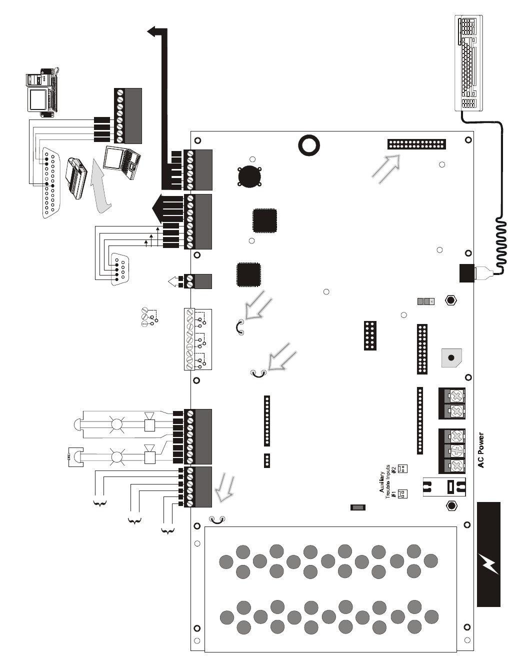
+BATTERY-
LCD DISPLAY KEYPAD I/F
OPT DACT
HOT
CB1
J3
J2
TB1 TB2
TB3
JP3
JP2
SW1
JP5
JP6
J17 J16
J6 J8
J7
PS2 Keyboard Interface
J10 J11
CUT TO
DISABLE
LOCAL
CHARGER
DISABLE
GND
FLT
CUT TO
MONITOR 4XTMF
OPT SLC
4XTMF OPT BD
TB4 TB5 TB6 TB7
DB9F
TB8
NEUT EARTH
Cut this jumper to disable the
FACP battery charger when
using external charger.
Cut this jumper to enable
Supervisory relay when
4XTMF module is installed
Connectors for 4XTMF option module
To disable ground fault detection,
remove jumper/shunt from JP2
Resettable Power - 24 VDC filtered, power-limited
(3.00 amps maximum) to smoke detectors (IDC).
Supervision required.
Nonresettable Power #1 - 24 VDC filtered,
power-limited (3.00 amps maximum)
Supervision required. Suitable for
powering annunciators.
Nonresettable Power #2 - 24 VDC filtered,
power-limited (3.00 amps maximum)
Supervision required. Suitable for
powering annunciators.
NAC #1
Style Y (shown)
or Style Z
3.0 amps max.
NAC #2
Style Y or
Style Z (shown)
3.0 amps max.
Contact Ratings:
2.0 amps @ 30 VDC (resistive)
0.5 amps @ 30 VAC (resistive)
Contacts shown below in normal
condition (AC power with no alarm,
trouble or supervisory activity).
(*
)
Factory default relay programming
as shown on circuit board
A Fail Safe Trouble
relay switches to the
NO position during
trouble conditions and
under loss of all power.
For EDP-listed equipment or
personal computer with FACP
Upload/Download Utility.
50 foot maximum within same room.
Refer to the SLC Wiring
Manual for detailed
information on wiring
addressable devices
for Style 4, 6 and 7.
ACS (EIA-485)
to ACS Annunc.
or UDACT-F
(power-limited,
supervised)
ELR 4.7K, ½W
DC Power Outputs (24 VDC)
Supervise with a power supervision relay A77-716B
Battery
MS-9600 Basic System Connections
Notification Appliance Circuits
2 Programmable Relays &
1 Fixed Trouble Relay
EIA-232
to printer or
personal computer
SLC Loop
OR
2
1
4
3
6
5
Connector for Optional 2nd
Signalling Line Circuit Module
Flash Memory Load Enable Switch.
UP is normal position for switch.
DOWN position allows loading of
factory software upgrades
Cut this jumper to supervise
the 4XTMF module when
installed (see JP10 & JP11)
+ + +B
+B
+
B
-
B
-
A
+A
+
A
-
A
-
shield
- - -NO NC C NC NO C NO NC C
Alarm* Trouble Supervisory*
Black
5 4 3 2 1
9 8 7 6
Green
White
Red
T
XR
C
V
D
T
R
TB7 (option to DB-25)
5 4 3 2 1
25 24 23 22 21 20 19 18 17 16 15 14
9 8 7 613 12 11 10
+
-
TERM
(EIA-485)
to LCD-80F
I
N
+
O
U
T
+
I
N
-
O
U
T
-
B
+B
-
BA
+A
-
A
CAUTION! HIGH VOLTAGE
NC NO C
+
++
+
+
+
120 VAC, 60 HZ, 3.2 amps 24 VDC, 25 Amp Hour maximum
T
XR
C
V
D
T
R
G
N
D
G
N
D
9600lay3.cdr
Unimode 9600 PN 51336:C 11/06/01 11
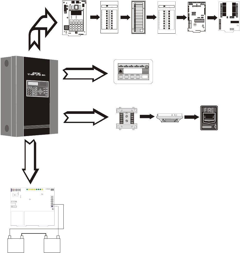
Peripheral Devices and Their Documents:
1
Ack/Step Silence Reset
Drill
Hold 2 sec.
ADT-LCD-80F
Doc. # 51589
ADT-AFM-16A
Doc. # A15207
ADT-LDM-32
Doc. # 51351
ADT-AFM-16AT &
ADT-AFM-32A
Doc. # A15048
ADT-ACS Series
Doc. # 51353 ADT-ACM-8R
Doc. # 51356
Addressable Devices and SLC Wiring
Doc. # 51309
ADT-CHG-120 Charger
Doc. # 50938
ADT-UDACT
Doc. # 50934
TERM (EIA-485)
Annunciators
ACS (EIA-485)
Annunciators
SLC Loop
Battery Connector
Unimode 9600
Doc. # 51336
9600peri.cdr
3URGXFW'HVFULSWLRQ ,QYHQWRU\
8QLPRGH31&
SECTION 1 Product Description
The ADT Unimode 9600 is a compact, cost effective, intelligent addressable FACP (Fire
Alarm Control Panel) with an extensive list of powerful features. The combination of
newer series devices and legacy 300 Series devices, along with the Unimode 9600 FACP,
offer the latest in fire protection technology. The power supply and all electronics are
contained on a single circuit board housed in a metal cabinet, providing a complete fire
control system for most applications. Optional modules, which plug into the main circuit
board, are available for special functions. Available accessories include LED, graphic and
LCD annunciators, reverse polarity/city box transmitter, digital alarm communicator/
transmitter, SLC expansion module, local and remote upload/download software and
remote power expansion.
1.1 Inventory
When the Unimode 9600 shipment is received, check to make certain that all parts have
been included in the shipment. The Unimode 9600 shipment should consist of one of each
of the following:
✓main circuit board with display
✓backbox with door
✓plastic bag containing screws, cables, key, etc.
✓manual
1.2 Features and Options
• Single standard addressable SLC loop which meets NFPA Style 4, 6 and 7
requirements
• Optional module for adding a second SLC loop which meets NFPA Style 4, 6 and 7
requirements
• 318 addressable device capacity for each SLC loop (159 detectors and 159 control/
monitor modules)
• 99 software zones
• Two onboard NACs (Notification Appliance Circuits) with additional NAC
capability using control modules
• 6.0 amps total power for NACs and 24 VDC auxiliary power outputs
• 7.2 amps total system power (includes battery charger)
• Two programmable relay outputs and one fixed trouble relay
• EIA-232 Printer/PC interface (variable baud rate)
• 80-character LCD display (backlit)
• Real-time clock/calendar with daylight savings time control
• History file with 1,000 event capacity
• Advanced fire technology features:
✓Automatic drift compensation
✓Maintenance alert
✓Detector sensitivity test capability (NFPA 72 compliant)
✓Automatic device type-code verification
✓Point trouble identification
• Waterflow selection per module point
• Alarm verification selection per detector point
• Walktest, silent or audible
• PAS (Positive Alarm Sequence) and Pre-signal per point (NFPA 72 compliant)
Features and Options Product Description
Unimode 9600 PN 51336:C 11/06/01 13
• Annunciators:
✓ADT-AFM-LED Zone Annunciator Series
✓ADT-LDM Graphic Annunciator Series
✓ADT-LCD-80F Liquid Crystal Display point annunciator
✓ADT-ACM-8R Relay Module
• Silence inhibit timer option per NAC
• Autosilence timer option per NAC
• Continuous, March Time, Temporal or California code for main circuit board NACs
with two-stage capability
• Selectable strobe synchronization per NAC
• Remote Acknowledge, Alarm Silence, Reset and Drill via addressable modules,
ADT-AFM annunciators or ADT-LCD-80F Remote annunciator
• Auto-program (learn mode) reduces installation time. Reports two devices set to
the same address
• Password and key-protected nonvolatile memory
• User programmable password
• Fully programmable from local keypad or keyboard or local PC
• SLC operates up to 10,000 ft. (3,000 m) with twisted, shielded wire or 3,000 ft (900
m) with untwisted, unshielded wire
• Compatible with newer series devices (CLIP Mode)
✓CP350: addressable Ionization Smoke Detector
✓SD350(T): addressable Photo Smoke Detector (T= with Thermal Sensor)
✓H350(R): Fast Response Heat Detector (R=Rate-of-Rise option)
✓D350P(R): addressable Photo Duct Detector (R=alarm relay option)
✓B501BH & B501BHT Sounder Bases
✓BB224RB Relay Base
✓BB224BI Isolator Base
✓MMF-300: Monitor Module
✓MDF-300: Dual Monitor Module (uses two consecutive SLC addresses)
✓MMF-301: Miniature Monitor Module
✓MMF-302: 2-wire Detector Module
✓CMF-300: Control Module
✓CRF-300: Relay Module
✓ADT-BG-12LX: Manual Pull Station
✓I300: Isolator Module
• Compatible with legacy 300 Series devices (CLIP Mode only):
✓CP300: addressable Ionization Smoke Detector
✓SD300(T): addressable Photoelectric Smoke Detector (T= Thermal Sensor)
✓C304: Control Module
✓M300: Monitor Module
✓M301: Miniature Monitor Module
✓M302: 2-wire Detector Module
✓ADT-BG-10LX: Manual Pull Station
• Optional 4XTMF module (conventional reverse polarity/city box transmitter)
Product Description Specifications
14 Unimode 9600 PN 51336:C 11/06/01
1.3 Specifications
AC Power - TB1
120 VAC, 60 Hz, 3.2 amps
Wire size: minimum 14 AWG (2.00 mm2) with 600 V insulation
Battery (Lead Acid Only) - TB2
Maximum Charging Circuit: Normal Flat Charge - 27.6 VDC @ 1.00 amp
Maximum Battery Charger Capacity: 25 Amp Hour (Unimode 9600 cabinet holds
maximum of two 18 Amp Hour batteries. For greater than 25 Amp Hour up to 120 Amp
Hour batteries, use the ADT-CHG-120 Battery Charger and BB-55F Battery Box.
Note: Jumper JP3, on the FACP main circuit board, must be cut to disable the FACP
battery charger when using the ADT-CHG-120.
Communication Loop - (Standard ) TB8 and (Optional SLC Expander Module) J3
24 VDC nominal, 27.6 VDC maximum
Maximum length is 10,000 ft. (3,000 m) total twisted, shielded pair length
Maximum loop current is 400 mA (short circuit) or 100 mA (normal)
Maximum loop resistance is 40 ohms
Supervised and power-limited
Refer to SLC Loop manual for wiring information
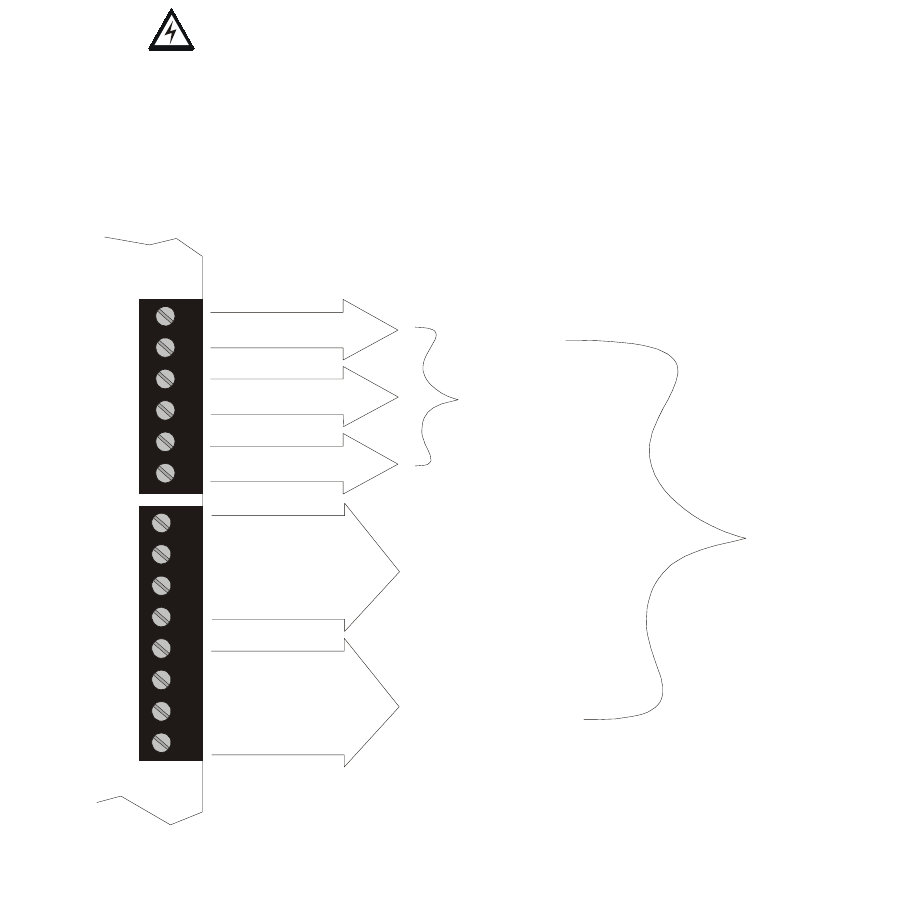
Notification Appliance Circuits - TB4
Power-limited circuitry
Maximum voltage drop in wiring: 2.0 VDC
Nominal operating voltage: 24 VDC
Current-limit: fuseless, electronic, power-limited circuitry
Maximum signaling current per circuit: 3.00 amps (see Figure 1.1 on page 15)
End-of-Line Resistor: 4.7 kΩ, ½ watt (P/N 71252 UL listed) for NACs
Refer to ADT Device Compatibility Document for listed compatible devices
Two Programmable and One Fixed Output Relay - TB5
Contact rating: 2.0 amps @ 30 VDC (resistive), 0.5 amps @ 30 VAC (resistive)
Form-C relays
Refer to Figure 2.5 on page 28 for information on power-limited wiring for relay circuits
Four-Wire Resettable Smoke Detector Power (24 VDC nominal) - TB3,
Terminals 1 (+) & 2 (-)
Maximum ripple voltage: 10 mVRMS
Up to 3.0 amps is available for powering 4-wire smoke detectors (see Figure 1.1)
Power-limited circuit
Refer to ADT Device Compatibility Document for listed compatible devices
Nonresettable Power #1 (24 VDC Nominal) - TB3, Terminals 3 (+) & 4 (-)
Maximum ripple voltage: 10mVRMS
Total DC current available from each output is up to 3.00 amps (see Figure 1.1)
Power-limited circuit
Nonresettable Power #2 (24 VDC Nominal) - TB3, Terminals 5 (+) & 6 (-)
Maximum ripple voltage: 10mVRMS
Total DC current available from each output is up to 3.00 amps (see Figure 1.1)
Power-limited circuit
Specifications Product Description
Unimode 9600 PN 51336:C 11/06/01 15
EIA-485 (ACS) - TB6
ACS annunciator connector, Terminal 1 (+) and Terminal 2 (-)
EIA-485 (TERM) - TB7
Terminal Mode annunciator connector, Terminal 5 (In +), 6 (In -), 7 (Out +), 8 (Out -)
EIA-232 (ACS) - TB7
PC/Printer Connector, Terminal 1 (Transmit), 2 (Receive), 3 (DTR), 4 (Ground)
Auxiliary Trouble Inputs - J16 & J17
Two-pin connectors which can be used to monitor trouble conditions on auxiliary
equipment. They can be connected to the trouble bus of a peripheral such as the ADT-
CHG-120 or to the normally-open dry contacts of a trouble relay.
CAUTION! Do not connect power to these connectors since circuit damage may result.
1.3.1 Current Availability
The following figure illustrates the maximum current that is possible for each panel circuit
and the total current available from the FACP power supply.
3 amps max
per circuit
3 amps max
per circuit
3 amps max
per circuit
3 amps max
per circuit
3 amps max
per circuit
Resettable Power
for 4-Wire
Smoke Detectors
Nonresettable
Power # 1
Nonresettable
Power # 2
NAC # 1
NAC # 2
Standby
6 amps max
per panel
Alarm
7 amps max
per panel
1
2
3
4
5
6
7
8
1
2
3
4
5
6
TB4
TB3
Figure 1.1 Current Availability
Refer to the battery calculations section for additional information.

Product Description Controls and Indicators
16 Unimode 9600 PN 51336:C 11/06/01
1.4 Controls and Indicators
LCD Display
The FACP uses an 80-character (4 lines
X 20 characters) high viewing angle
LCD display. The display includes a
long life LED backlight that remains
illuminated. If AC power is lost and the
system is not in alarm, the LED
backlight will turn off to conserve batteries.
LED Indicators
LED indicators are provided to annunciate the following conditions:
• AC Power (green)
• Fire Alarm (red)
• Supervisory (yellow)
• Trouble (yellow)
• Maintenance/presignal (yellow)
• Alarm Silenced signals (yellow)
• Disabled (yellow)
• Battery fault (yellow)
• Ground fault (yellow)
Key Panel
Mounted on the main circuit board, the key panel includes a window for the LCD display
and LED indicators as listed above. The key panel, which is visible with the cabinet door
closed, has 25 keys, including a 16 key alpha-numeric pad similar to a telephone keypad.
Function keys:
• Acknowledge/Step
• Alarm Silence
• Drill
• Reset (lamp test)
Service/program keys:
• Keys labeled 1 to 9
• * key
• # key
• 0 (recall) key
•1st Event key
• Clear key
• Escape key
• Mode key
• Four cursor keys (up, down, left and right)
• Enter key
Local Piezo Sounder
A piezo sounder provides separate and distinct pulse rates for alarm, trouble and
supervisory conditions.
SYSTEM ALL NORMAL
10:00A 010101
1
4
*
2
5
0
3
6
#
1
st
EVENT
ABC DEF
GHI JKL MNO
PRS TUV WXY
QZ
-/.
CLR
78 9
ESC
ENTER
RECALL
ACK/STEP
ALARM
SILENCE
DRILL
HOLD 2 SEC
RESET
MODE
MAINTENANCE
ALARM
SILENCED
DISABLED
BATTERY
GROUND
SUPERVISORY
TROUBLE
AC POWER
FIRE ALARM
Figure 1.2 Membrane/Display Panel
9600kypd.cdr

Circuits Product Description
Unimode 9600 PN 51336:C 11/06/01 17
1.5 Circuits
SLC Communication Loop
One SLC loop is provided standard on the FACP main circuit board. A second SLC loop
is available by plugging the optional SLC module into connector J3 on the main circuit
board. SLC loops, configurable for NFPA Style 4, 6 or 7, provide communication to
addressable detectors, monitor (initiating device) and control (output device) modules.
Refer to the ADT SLC Wiring Manual for information on wiring devices.
Output Circuits
The following output circuits are available on the FACP:
• 24 VDC Resettable (smoke detector power) output - 3.00 amps maximum
• 24 VDC Nonresettable power output #1 - 3.00 amps maximum
• 24 VDC Nonresettable power output #2 - 3.00 amps maximum
• 24 VDC Battery Charger (up to 25 AH batteries)
NAC (Notification Appliance Circuits)
Two NACs, configurable for Style Y (Class B) or Style Z (Class A), are provided with
various programmable features.
Relays
One fixed and two fully programmable Form-C dry contact relays are provided. The fixed
fail-safe relay monitors system trouble and the two programmable relays are factory
default programmed for system alarm and system supervisory. Contacts are rated 2.0
amps @ 30 VDC (resistive) and 0.5 amps @ 30 VAC (resistive). The programmable
relays can be programmed for the following operations:
• fire alarm
• trouble
• supervisory
• supervisory auto-resettable
• DACT communication failure
• process monitor
• process monitor auto-resettable
• hazard alert
• medical alert
•AC loss
Auxiliary Trouble Inputs
Auxiliary Trouble Inputs can be connected to trouble bus outputs from auxiliary
equipment, such as power supplies, or normally-open dry contacts of a trouble relay to
allow monitoring by the Unimode 9600.
1.6 Components
Main Circuit Board
The main circuit board contains the system’s CPU, power supply, other primary
components and wiring interface connectors. Optional modules plug in and are mounted
to the main circuit board. The circuit board is delivered in the Unimode 9600 kit and must
be mounted to the backbox. Refer to the circuit board illustration on Page 10.
Reference
Manual
See Page
Product Description Components
18 Unimode 9600 PN 51336:C 11/06/01
Cabinet
The Unimode 9600 cabinet is red with a navy blue front overlay.
The backbox provides space for two batteries (up to 18 Amp
Hour). Ample knockouts are provided for system wiring. Also
included is a standard dress panel, which mounts to the inside of
the cabinet (required on the ULC version). The dress panel must
be installed to meet FM requirements.
Batteries
The Unimode 9600 cabinet provides space for two batteries (up to
18 Amp Hour). Batteries larger than 18 Amp Hour up to 25 Amp Hour require use of UL
listed battery cabinet. The ADT-CHG-120 can be used for charging 25 to 120 AH
batteries and the BB-55F can be used for housing the batteries. Batteries must be ordered
separately.
1.6.1 Intelligent Addressable Detectors: Newer Series
Intelligent, addressable detectors provide information to the control panel on an SLC
Signaling Line Circuit (refer to the ADT SLC Wiring Manual for detailed information on
device installation, wiring and operation). This allows the control panel to continually
process the information to determine the status (alarm, trouble, maintenance or normal) of
each detector. Each detector responds to an SLC address that is set in the detector head
using built-in rotary decimal switches with the ability to select up to 159 addresses. Note
that a blinking LED on an intelligent detector indicates communication between the
detector and the control panel. Refer to the ADT Device Compatibility Document for a
list of approved detectors.
Smoke Detectors (Photoelectric)
The SD350 is an intelligent, addressable low profile photoelectric smoke detector which
provides smoke sensing technology. The SD350T includes a 135o fixed thermal sensor.
Smoke Detector (Ionization)
The CP350 is an intelligent, addressable low profile ionization smoke detector which
measures the level of combustion products in its chamber using the ‘ionization principle.’
Smoke Detector (Duct)
The D350P is an intelligent, addressable photoelectric duct smoke detector. The D350RP
includes an alarm relay.
Heat Detectors
The H350 is an intelligent heat detector with a thermistor sensing circuit for fast response,
designed to provide open area protection with 50 foot (15 m) spacing capability. The
H350R incorporates a thermal Rate-of-Rise circuit of 15oF (9.4oC).
Detector Bases
The B501BH is a standard sounder base and the B501BHT is a temporal tone sounder
base for intelligent, addressable smoke detectors.
The B224RB is a relay base with one Form-C relay for intelligent, addressable smoke
detectors. It may be used to control auxiliary functions.
The B224BI is an isolator base for intelligent, addressable smoke detectors. It functions
similar to the I300 isolator module which allows loops to operate under fault conditions
and automatically restore when the fault is removed.
uni-600.cdr

Components Product Description
Unimode 9600 PN 51336:C 11/06/01 19
1.6.2 Intelligent Addressable Modules: Newer Series
The newer series of Control Modules and Monitor Modules provide an interface between
the control panel and conventional notification and initiating devices. Each module can be
set to respond to an address with built-in rotary switches with the ability to select up to
159 addresses (a tab on the address switch must be broken off to use addresses 100-159).
A blinking LED on a monitor module indicates communication between the module and
the control panel. These devices can also be used in CLIP Mode (Classic Loop Interface
Protocol) when installed on older systems. Refer to the ADT Device Compatibility
Document for a list of approved notification and initiating devices.
Monitor Modules
The MMF-300, MDF-300 and MMF-302 are addressable monitor modules for monitoring
conventional initiating devices. The MMF-300 is used for normally open contact alarm
initiating devices, such as manual pull stations, four-wire smoke detectors, heat detectors,
waterflow, security contacts and supervisory devices. The MDF-300 is a dual monitor
module (Class B only) which occupies two consecutive SLC addresses, with each module
functionally the same as the MMF-300. The MMF-302 is used primarily for two-wire
smokes detectors in addition to normally open contact devices. The supervised IDCs
(Initiating Device Circuits) can be wired to the modules as NFPA Style B (Class B) or
Style D (Class A) circuits. The modules are supplied with a thermoplastic cover for
mounting to a 4-inch mounting box.
Monitor Module (miniature)
The MMF-301 is an addressable module that is functionally similar to an MMF-300 but
offered in a smaller package for mounting directly in the electrical box of the device being
monitored.
Control Module
The CMF-300 is an addressable Control Module used to connect NACs (Notification
Appliance Circuits) to power and supervise compatible, UL-listed notification appliances.
The NACs can be wired to the module as supervised NFPA Style Y (Class B) or Style Z
(Class A) circuits. The modules are supplied with a thermoplastic cover for mounting to a
4-inch square mounting box.
Relay Module
The CRF-300 is a Control Relay Module which is functionally similar to the CMF-300 but
used as a Form-C relay module.
Isolator Module
The I300 loop isolator module is an automatic switch which opens the circuit voltage to
the SLC loop branch(es) whenever a wire-to-wire short circuit is detected on that loop.
The remainder of the communications loop leading up to the I300 will continue to operate,
unaffected by the short. The isolator module is bidirectional, meaning that it can detect a
fault condition between the input SLC terminals or output SLC terminals. The I300 is
required to meet NFPA Style 7 requirements.
Detector Annunciator
The RA400Z is a remote single LED annunciator that can be wired directly to an
addressable detector for annunciation of that detector’s alarm status.
Manual Pull Station
The ADT-BG-12LX is an addressable manual pull station featuring a key-lock reset. The
pull station responds to an address set by the installer using the built-in rotary decimal
switches on the pull station. The manual pull station includes an ADT key.
Reference
Manual
Product Description Optional Modules
20 Unimode 9600 PN 51336:C 11/06/01
1.6.3 300 Series Intelligent Addressable Devices
ADT’s 300 Series Intelligent Addressable Devices are fully compatible with the Unimode
9600 FACP. The devices must be configured for CLIP Mode operation if the control panel
is installed in an existing system with 300 Series devices. The address of 300 Series
devices cannot be set above 99. Compatible devices include:
• SD300 Photoelectric Detector
• SD300T Photoelectric Detector with Thermal Sensor
• CP300 Ionization Detector
• M300 Monitor Module
• M301 Miniature Monitor Module
• M302 2-wire Monitor Module
• C304 Control/Relay Module
• ADT-BG-10LX Manual Pull Station
1.6.4 Addressable Device Accessories
End-of-Line Resistor Assembly P/N R-47K
The 47 kΩ End-of-Line Resistor assembly (P/N: R-47K) is used to supervise the MMF-
300, MDF-300, MMF-301 and CMF-300 module circuits. The 3.9 kΩ End-of-Line
Resistor assembly is used to supervise the MMF-302 module circuit. The resistors are
included with each module.
Power Supervision Relay
The UL listed End-of-Line power supervision relay is used to supervise the power to 4-
wire smoke detectors and notification appliances.
N-ELR Mounting Plate
The N-ELR is a single End-of-Line resistor plate which is required for use in Canada. An
ELR, which is supplied with each module and fire alarm control panel, is mounted to the
ELR plate. Resistors mounted to the N-ELR plate can be used for the supervision of a
monitor and control module circuit.
1.7 Optional Modules
The Unimode 9600 main circuit board includes option module connectors for the
following modules:
4XTMF Transmitter Module
The 4XTMF provides a supervised output for local energy municipal box transmitter,
alarm and trouble reverse polarity. It includes a disable switch and disable trouble LED.
A jumper on the module is used to select an option which allows the reverse polarity
circuit to open with a system trouble condition if no alarm condition exists. The module
plugs into connectors J10 and J11 which are located near the top center of the main circuit
board. When the 4XTMF module is installed, Jumper JP6, on the main circuit board, must
be cut to allow supervision of the module.
SLC-2 Expander Module
The SLC-2 Expander Module allows expansion of the Unimode 9600 from one SLC
circuit to two SLC circuits. The module plugs into connector J3 which is located in the
lower right corner of the main circuit board. The wiring for the second SLC connects to
terminals located on the expander module.
Accessories Product Description
Unimode 9600 PN 51336:C 11/06/01 21
1.8 Accessories
1.8.1 PK-9600 Programming Utility
The PK-9600 Programming Utility can be used to program an Unimode 9600 directly
from most IBM compatible computers, including laptops and portables, equipped with a
serial port. Unimode 9600 program files can also be created and stored on the PC and then
downloaded to the control panel. The PK-9600 Kit includes the Windows-based
Programming Utility software on CD-ROM with on-line help file. A serial cable (P/N:
PRT/PK-CABLE), which must be purchased separately, is required for connection of the
PC to the RS-232 (PC/Printer) terminals at TB7 of the Unimode 9600 main circuit board.
Refer to the illustration on page 10 and the section titled "Printer/PC" on page 34, for the
location and connections to this terminal.
1.8.2 Dress Panel
A dress panel is provided standard with the Unimode 9600 (required for Canadian
installations). The dress panel restricts access to the system wiring while allowing access
to the key panel.
Note that the Unimode 9600 FACP, installed with the dress panel, has received Factory
Mutual (FM) approval. FM approval is contingent on the proper installation of the dress
panel.
1.8.3 Battery Box
BB-17F
The BB-17F battery box may be used to house up to two 18 AH batteries in the event that
room is not available in the main cabinet due to the use of a ADT-UDACT, 411UD, etc.
The battery box mounts directly below the FACP cabinet. The battery box is red and is
provided with knockouts.
CAUTION: HIGH VOLTAGE UNDER PANEL
!! WARNING !!
SEVERAL DIFFERENT SOURCES OF POWER
CAN BE CONNECTED TO THIS CONTROL UNIT
DISCONNECT ALL SOURCES OF POWER BEFORE SERVICING
dp9600.cdr
bb-17f.cdr

Product Description Accessories
22 Unimode 9600 PN 51336:C 11/06/01
BB-55F
The BB-55F battery box may be used to house two 25 AH batteries, two 60 AH batteries
or one 100 AH battery. When the ADT-CHG-120 is mounted in the BB-55F, two 25 AH
or one 60 AH battery may also be housed in the battery box.
1.8.4 ADT-CHG-120 Battery Charger
The ADT-CHG-120 is capable of charging up to 120 AH lead-acid batteries with the
Unimode 9600 FACP. The FACP battery charger must be disabled when using the
ADT-CHG-120. The batteries and charger can be housed in the BB-55F battery box
which can be mounted up to 20 feet away from the control panel. Note that when using
the BB-55F for housing the charger and batteries greater than 25AH, multiple BB-55Fs
are required. Refer to the ADT-CHG-120 Manual for additional information.
1.8.5 Annunciators
ADT-ACS Series LED Zone Type Annunciators
The ADT-ACS Series Annunciators remotely display alarm and trouble status as well as
system status. In addition, they can provide remote Acknowledge, Silence, Reset and
Drill functions. For more detailed information, refer to the appropriate ADT-ACS
annunciator manual. Following is a list of annunciators which can be used with the
Unimode 9600.
• ADT-ACM-16AT Annunciator Control Module annunciates 16 zones with 16 red
alarm LEDs and 16 yellow trouble LEDs. In addition, it has a System Trouble
LED, an On Line/Power LED and a local piezo sounder. It also has switches for
FACP Acknowledge, Silence, Reset and Drill. It has rotary address switches and
will accept up to three AEM-16AT Expanders
• AEM-16AT Annunciator Expander Module annunciates 16 zones with 16 red alarm
LEDs and 16 yellow trouble LEDs
• ADT-AFM-16AT Annunciator Fixed Module annunciates 16 zones with 16 red
alarm LEDs and 16 yellow trouble LEDs. In addition, it has a System Trouble
LED, an On Line/Power LED and a local piezo sounder. It also has switches for
FACP Acknowledge, Silence, Reset and Drill. It is fixed at address ‘1’
• ADT-ACM-32A Annunciator Control Module annunciates 32 alarm zones with 32
red LEDs. In addition, it has a System Trouble LED, an On Line/Power LED and a
local piezo sounder. It also has a switch for local piezo silence. It has rotary
address switches and will accept one AEM-32A Expander
• AEM-32A Annunciator Expander Module annunciates 32 alarm zones with 32 red
LEDs
• ADT-AFM-16A Annunciator Fixed Module annunciates 16 alarm zones with 16
red alarm LEDs. In addition, it has a System Trouble LED, an On Line/Power LED
and a local piezo sounder. It also has a switch for local piezo silence. It is fixed at
address ‘1’
• ADT-AFM-32A Annunciator Fixed Module annunciates 32 alarm zones with 32
red LEDs
bb-55f.cdr
Reference
Manual
Reference
Manual

Getting Started Product Description
Unimode 9600 PN 51336:C 11/06/01 23
ADT-LCD-80F Remote Fire Annunciator
The ADT-LCD-80F annunciator is a compact 80-character backlit LCD remote fire
annunciator that is capable of displaying English language text. It mimics the display on
the control panel and will annunciate device type, point alarm, trouble or supervisory
condition, zone assignment plus any custom alpha labels programmed into the FACP. The
annunciator also provides system status LEDs to display AC Power, Alarm, Trouble,
Supervisory and Alarm Silenced conditions. Additionally, the ADT-LCD-80F is capable
of remotely performing critical system functions such as Acknowledge, Silence, Reset and
Drill.
Communications between the control panel and the annunciator is accomplished over a
serial interface employing the EIA-485 communication standard. Up to 32 ADT-LCD-
80F annunciators may be connected to the EIA-485 circuit. The annunciators may be
powered from the host FACP or a remote UL listed filtered power supply such as the
FCPS Series. For more detailed information, refer to the ADT-LCD-80F manual.
ADT-LDM Series Lamp Driver Modules (Graphic Annunciator)
The ADT-LDM Series Lamp Driver Modules, which consist of the ADT-LDM-32 master
and ADT-LDM-E32 expander modules, are used to provide an interface to a custom
graphic LED annunciator. The master module provides power and control for a maximum
of three expander modules. The ADT-LDM-32 and ADT-LDM-E32 have output
connectors which are used to drive lamps or LEDs and input connectors which are used
for remote switch functions. Refer to the ADT-LDM Series Lamp Driver Modules
manual for a complete description.
1.9 Getting Started
The following is a brief summary of the minimal steps involved in bringing an Unimode
9600 on-line:
• Install Backbox and Main Circuit Board (refer to "Mounting" on page 24)
• Address and Install Intelligent Devices (refer to the SLC Wiring Manual)
• Enter Autoprogramming (refer to "Autoprogram" on page 87)
• Resolve Programming Conflicts
Go to Point Program to Enter Specific Data (refer to "Point Program" on page 43). Use
the right and left arrow keys to navigate between devices.
Reference
Manual
Reference
Manual
Installation Mounting
24 Unimode 9600 PN 51336:C 11/06/01
SECTION 2 Installation
The cabinet may be either semi-flush or surface mounted. The cabinet mounts using two
key slots and two 0.250” (6.35 mm) diameter holes located in the backbox. The key slots
are located at the top of the backbox and the two securing holes at the bottom.
Carefully unpack the system and check for shipping damage. Mount the cabinet in a
clean, dry, vibration-free area where extreme temperatures are not encountered. The area
should be readily accessible with sufficient room to easily install and maintain the panel.
Locate the top of the cabinet approximately 5 feet (1.5 m) above the floor with the hinge
mounting on the left. Determine the number of conductors required for the devices to be
installed. Sufficient knockouts are provided for wiring convenience. Select the
appropriate knockout(s) and pull the conductors into the box. All wiring should be in
accordance with the National and/or Local codes for fire alarm systems.
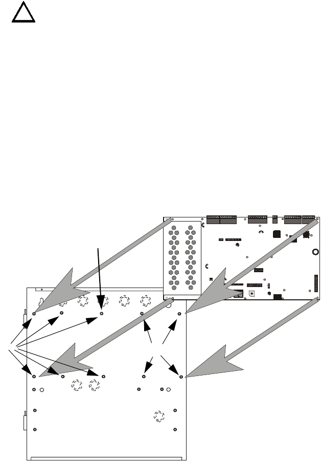
2.1 Mounting
The circuit board contains static-sensitive components. Always ground yourself with a
proper wrist strap before handling any boards so that static charges are removed from the
body. Use static suppressive packaging to protect electronic assemblies.
✓Mark and predrill holes in the wall for the top two keyhole mounting bolts using
the dimensions illustrated in Figure 2.2 on page 25
✓Install two upper fasteners in the wall with the screw heads protruding
✓Using upper ‘keyholes,’ place backbox over the two screws, level and secure
✓Mark and drill the lower two holes
✓Mount backbox, install remaining fasteners and tighten
✓Screw supplied standoffs onto mounting studs in locations indicated below
✓When the location is dry and free of construction dust, install the main circuit
board by aligning the 10 mounting holes in the circuit board with the 10
mounting standoffs in the backbox as illustrated below
✓Secure the circuit board to the standoffs with the supplied screws and male/
female standoff as indicated in following figure
!
See Page
+BATTERY-
LCD DI SPL AY KEYPAD I/F
OPT DACT
HOT
CB1
J3
J2
TB1 TB2
TB3
JP3
JP2
SW1
JP5
JP6
J17 J16
J6 J8
J7
JP10 JP11
CUT T O
DISABLE
LOCA L
CHA RGE R
DISABLE
GND
FLT
CUT T O
MO NI TO R 4 XTM
OPT SLC
4XTM O PT BD
TB4 TB5 TB6 TB7 TB8
NEUT EARTH
Figure 2.1 Unimode 9600 Main Circuit Board Installation
Unimode 9600 Backbox
Unimode 9600 Main Circuit Board
mounting studs mounting studs
96brdmnt.cdr
IMPORTANT!
Secure circuit board to this standoff
with supplied male/female standoff
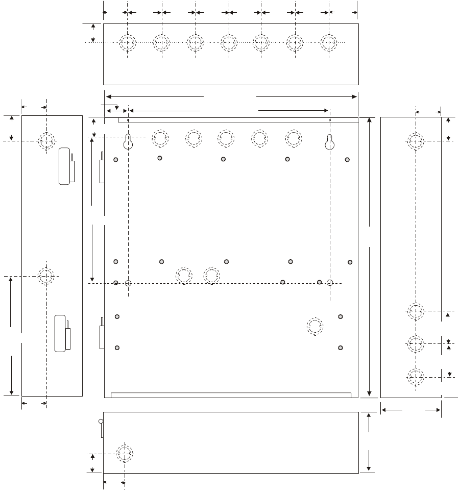
Mounting Installation
Unimode 9600 PN 51336:C 11/06/01 25
1.75“
4.45 cm
3.79 cm 3.81 cm
1.50“ (3.81 cm)
1.50“
15.5“ (39.37 cm)
47.0cm
18.5“
1.50“
3.81 cm
1.50“ (3.81 cm)
1.75“
4.45 cm
11.1 cm
4.37“
12.00“ (30.48 cm)
1.62“ (4.11 cm)
1.49“
4.1 cm
1.62“ 4.1cm
1.62“
1.75“
2.00“
2.00“
2.00“2.00“
2.00“
5.1 cm
2.00“
10.0“
25.4 cm
4.37“
11.1 cm
17.35 cm
6.83“
4.1cm
1.583“
4.45cm
1.75“
4.45cm
1.75“
1.453“ (3.69 cm)
Figure 2.2 Unimode 9600 Cabinet Mounting
9600encl.cdr
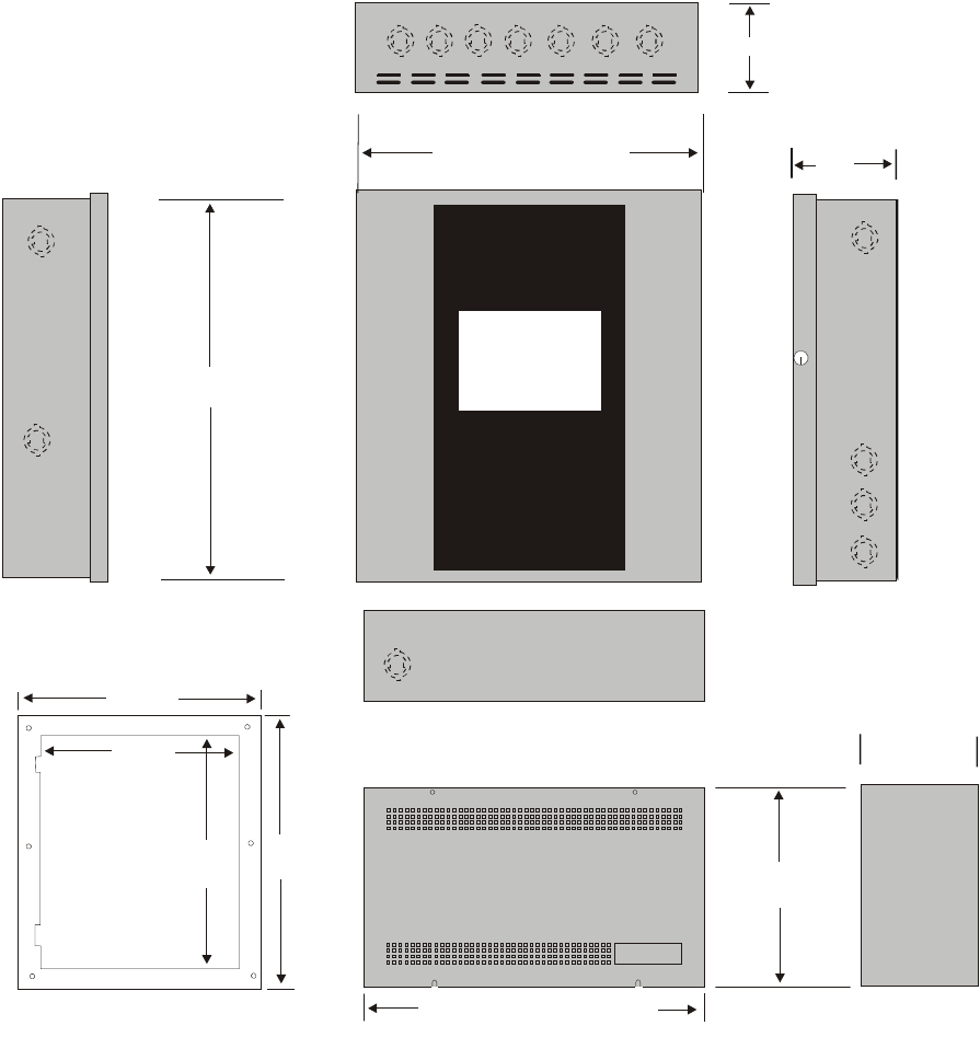
Installation Mounting
26 Unimode 9600 PN 51336:C 11/06/01
Top
Left Side Right Side
Bottom
Depth = 4.75"
(12.07 cm)
Battery Box = 8.5"
(21.59 cm)
Battery Box = 14.34" (36.42 cm)
Trim Ring
P/N:FC-TR
21.620"
(54.92 cm)
18.625"
(47.308 cm)
15.625"
(39.688 cm)
18.620"
(47.3 cm)
Door = 18.67" (47.43 cm)
Backbox = 18.5" (47.0 cm)
Depth =
4.425"
(11.24 cm)
Door = 15.78" (40.08 cm)
Backbox = 15.5" (39.37 cm)
Depth = 4.37" (11.1 cm)
Figure 2.3 Unimode 9600 Cabinet Dimensions
9600cab.cdr
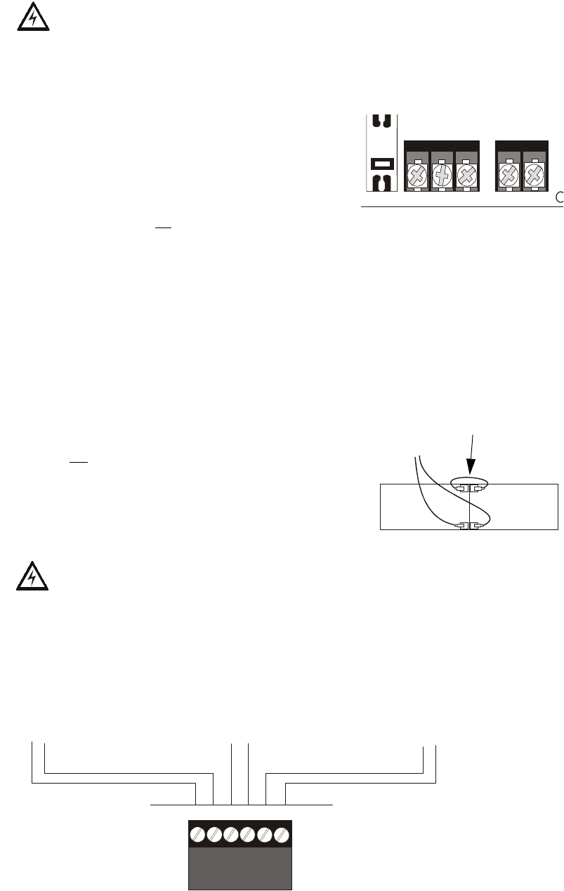
Power Installation
Unimode 9600 PN 51336:C 11/06/01 27
2.2 Power
WARNING: Several different sources of power can be connected to this panel.
Disconnect all sources of power before servicing. The panel and associated equipment
may be damaged by removing and/or inserting cards, modules or interconnecting cables
while this unit is energized.
2.2.1 AC Power and Earth Ground Connection
Primary power required for the FACP is 120 VAC,
60 Hz, 3.2 amps. Overcurrent protection for this
circuit must comply with Article 760 of the National
Electrical Code (NEC) and/or local codes. Use 14
AWG (2.00 mm2) or larger wire with 600 volt
insulation rating. Make certain that the AC mains
circuit breaker is off before making any wiring
connections between the mains and the control panel. Connect the wiring from the AC
mains to TB1 on the FACP, being careful to observe proper connections.
Connect a wire from the grounding stud in the cabinet to a known solid earth ground. This
connection is vital for maintaining the control panel’s immunity to unwanted transients
generated by lightning and electrostatic discharge. Apply AC power to the panel only
after the system is completely installed and visually checked. Note that AC power must be
applied to the panel before installing the battery interconnect cable (refer to the following
section).
2.2.2 Battery Power
Before connecting the batteries to the FACP, make
certain that the interconnect cable between the batteries
is not connected. Do not connect the interconnect cable
until the system is completely installed. Observe
polarity when connecting the batteries. Connect the
battery cable to TB2 on the main circuit board. Refer
"Power Supply Calculations" on page 127, for
calculation of the correct battery rating.
WARNING: Battery contains sulfuric acid which can cause severe burns to the skin and
eyes and can destroy fabrics. If contact is made with sulfuric acid, immediately flush the
skin or eyes with water for 15 minutes and seek immediate medical attention.
2.2.3 DC Power Output Connection
All DC power outputs are power-limited.
+BATTERY-
LCD DISPLAY
HOT
CB1
TB1 TB2
NEUT EARTH
-
-
+
+
Interconnect Cable
See Page
+ - + - + -
Figure 2.4 Power Outputs - 24 VDC
1 2 3 4 5 6
Power-limited Resettable Power
3.0 amperes max., 24 VDC nominal
filtered, resettable power can be drawn
from TB3 Terminals 1(+) and 2(-)
Power-limited Nonresettable Power #1
3.0 amperes max. , 24 VDC nominal
filtered, nonresettable power can be
drawn from TB3 Terminals 3(+) and 4(-)
Power-limited Nonresettable Power #2
3.0 amperes max. , 24 VDC nominal
filtered, nonresettable power can be
drawn from TB3 Terminals 5(+) and 6(-)
9600tb3.cdr
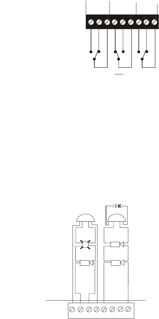
Installation Relays
28 Unimode 9600 PN 51336:C 11/06/01
2.3 Relays
The FACP provides two programmable Form-C relays and one fixed fail-safe Form-C
trouble relay, all with contacts rated for 2.0 amps @ 30 VDC (resistive) or 0.5 amps @ 30
VAC (resistive). The Alarm and Supervisory silk-screen labels reflect the factory default
programming for the two programmable relays.
Note that relay connections may be power-limited or nonpower-limited, provided that
0.25” spacing is maintained between conductors of power-limited and nonpower-limited
circuits. Refer to UL Power-limited wiring requirements.
2.4 Notification Appliance Circuits
The control panel provides two NAC (Notification Appliance Circuits) configurable for
Style Y/Class B or Style Z/Class A. Each circuit is capable of 3.0 amps of current. Total
system current cannot exceed 7.2 amps (refer to "Calculating the System Current Draw"
on page 128). Use UL listed 24 VDC notification appliances only. Circuits are supervised
and power-limited. Refer to the ADT Device Compatibility Document for a listing of
compatible notification appliances. The two NACs, which are located on the main circuit
board, may be expanded via the FCPS Series field charger/power supplies. Surge
protection for notification appliances may be provided by using one of the UL listed
compatible surge suppressors listed in the ADT Device Compatibility Document.
ALARM
RELAY
NO NC NONC NO NC
CCC
SUPV
RELAY
TROUBLE
RELAY
Figure 2.5 Relay Terminals
Relay contacts shown with power applied to panel and
no active troubles, alarms or supervisories
TB5
Note that the relays labeled as Alarm
Relay (Relay 1) and Supervisory Relay
(Relay 3) reflect the factory default
programming for these relays which are
programmable.
The relay labeled Trouble Relay (Relay 2)
is fixed and cannot be changed. It is a fail-
safe relay which will transfer on any
trouble or total power failure.
9600reyp.cdr
Reference
Manual
See Page
++
B+ A+ A- B- B+ A+ A- B-
1 2 3 4 5 6 7 8
Figure 2.6 NAC Connections
Style Y (Class B) Notification Appliance Circuit, supervised
and power-limited - 4.7 kohm, ½ watt P/N:71252 UL listed
Style Z (Class A) Notification Appliance Circuit,
supervised and power-limited
Polarized Bell Polarized Bell
Polarized Horn
Polarized Horn
Polarized Horn
Polarized Strobe
Notification Appliance Circuit
polarity shown in alarm state
Dummy Load all unused circuit
TB4
+
+
+
9600nac.cdr
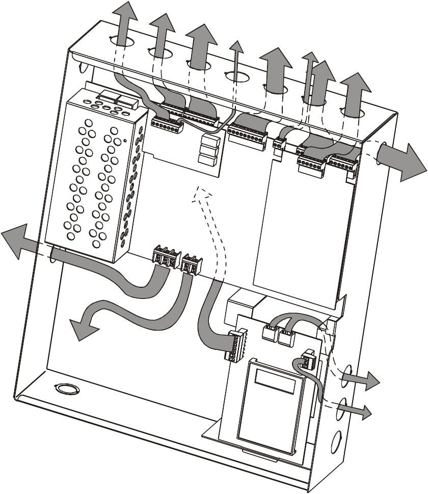
UL Power-limited Wiring Requirements Installation
Unimode 9600 PN 51336:C 11/06/01 29
2.5 UL Power-limited Wiring Requirements
Power-limited and nonpower-limited circuit wiring must remain separated in the cabinet.
All power-limited circuit wiring must remain at least 0.25” (6.35 mm) away from any
nonpower-limited circuit wiring and nonpower-limited circuit wiring must enter and exit
the cabinet through different knockouts and/or conduits. A typical wiring diagram for the
Unimode 9600 is shown below.
Figure 2.7 Typical UL Power-limited Wiring Requirements
Power-limited Circuits
Power-limited CircuitsNonpower-limited
Circuits
Power-limited
Circuits
4XTMF
SLC-2
ADT-UDACT
AC Power
Nonpower-limited
To Batteries
Nonpower-limited
Circuits
Power-limited
Circuits
To EIA-485 and
24 VDC power
routed behind
board
ms-9600wireroute.cdr
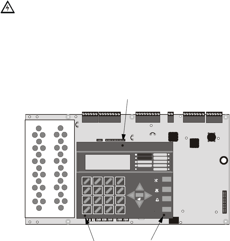
Installation Optional Modules and Devices
30 Unimode 9600 PN 51336:C 11/06/01
2.6 Optional Modules and Devices
WARNING! Disconnect all sources of power (AC and DC) before installing or removing
any modules or wiring.
Unimode 9600 Keypad/Display Removal
Removal of the keypad/display is normally not necessary. If, however, it becomes
necessary to replace the keypad/display, access the auxiliary trouble bus connectors at J16
and J17 or install future option modules, the Keypad/Display can be removed by inserting
a Phillips screwdriver into each of the three holes located in the flexible covering of the
Keypad/Display and loosening the three mounting screws. Note that it is not necessary to
disconnect the cables between the Keypad/Display and the main circuit board unless the
unit itself is being replaced. Carefully lift the Keypad/Display and rest the unit at the
bottom of the main circuit board.
+BATTERY-
LCD DISPLAY KEYPAD I/F
1
2
3
OPT DACT
HOT
CB1
J3
J2
TB1 TB2
TB3
JP3
JP2
JP8
JP4
JP7
JP5
JP6
JP6
J17 J16
J6 J8
J7
JP10
CUT TO
DISABLE
LOCAL
CHARGER
DISABLE
GND
FLT
CUT TO
MONITOR 4XTM
OPT SLC
4XTM OPT BD
TB4 TB5 TB6 TB7 TB8
NEUT EARTH
1
4
*
2
5
0
3
6
#
1
st
EVEN T
ABC DEF
GHI J KL MNO
PRS TUV WXY
QZ
-/.
CLR
78 9
ESC
ENTER
RECALL
ACK/STEP
ALARM
SILENCE
DRILL
HOLD 2 SEC
RESET
MODE
MAINTENANCE
ALARM
SILENCED
DISABLED
BATTERY
GROUND
TROUBLE
SUPERVISORY
FIRE ALARM
AC POWER
Figure 2.8 Keypad/Display Removal
Mounting Screw Access Hole
Mounting Screw Access Holes
96dact1.cdr
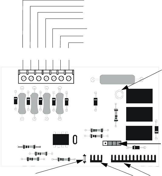
2SWLRQDO0RGXOHVDQG'HYLFHV ,QVWDOODWLRQ
8QLPRGH31&
2.6.1 4XTMF Transmitter Module Installation
The 4XTMF provides a supervised output for a local energy municipal box transmitter in
addition to alarm and trouble reverse polarity. A jumper option allows the reverse polarity
circuit to open with a system trouble condition if no alarm condition exists. A disable
switch allows disabling of the transmitter output during testing to prevent accidental
calling of the monitoring service.
Local Energy Municipal Box Service (NFPA 72 Auxiliary Fire Alarm Systems):
Supervisory Current: 5.0 mA
Trip Current: 350 mA (subtracted from notification appliance power)
Coil Voltage: 3.65 VDC
Maximum Coil Resistance: 14.6 ohms
Maximum allowable wire resistance between panel and trip coil: 3 ohms
Municipal Box wiring can leave the building
Remote Station Service (NFPA 72 Remote Station Fire Alarm Systems) - Intended
for connection to a polarity reversal circuit or a Remote Station receiving unit having
compatible ratings:
Maximum load for each circuit: 10 mA
Reverse polarity output voltage: 24 VDC
Remote Alarm and Remote Trouble wiring can leave the building
Before installing the module, place the disconnect switch to the right (disconnect) position
to prevent accidental activation of the municipal box. Note that a Disconnect LED will
illuminate after the module is installed in the Unimode 9600. In addition, the System
Trouble LED will turn on to indicate the Disconnect condition.
Figure 2.9 4XTMF Transmitter Module
Connect to FACP J10 & J11
Disconnect Switch
shown in disconnect
position
TBL Jumper
}Remote Alarm (power-limited)*
}Remote Trouble (power-limited)*
No connection
}Municipal Box (nonpower-limited)*
1 2 3 4 5 6 7
+ - + - + -
Polarities are shown for module activation
Note: 4XTMF Module is not suitable for
transmitting reverse polarity supervisory signal.
* Wiring from these
terminals can exit the
protected premises.
Dummy load terminals
6 and 7 (4.7kΩ, ¼ watt
resistor) if Municipal
Box is not connected.
Disconnect LED
4xtmfl.cdr
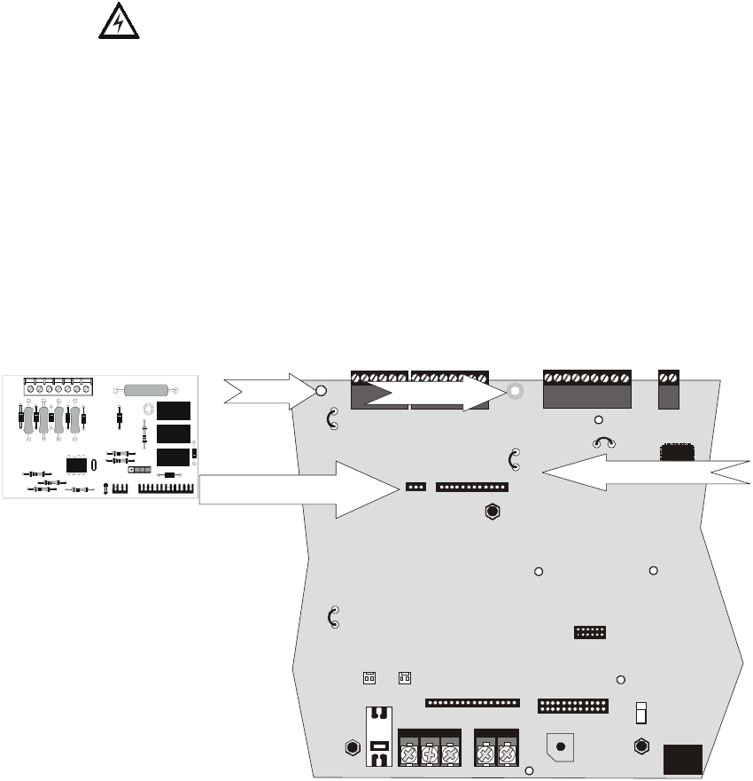
,QVWDOODWLRQ 2SWLRQDO0RGXOHVDQG'HYLFHV
8QLPRGH31&
The following steps must be followed when installing the 4XTMF module:
1. Remove all power (AC and DC) from the FACP before installing 4XTMF
2. Cut jumper JP6 on the main circuit board to allow the control panel to supervise the
4XTMF module
3. Carefully plug the connectors on the 4XTMF module into connectors J10 and J11
on the Unimode 9600 main circuit board, being careful not to bend any pins
4. Secure 4XTMF module to standoffs with supplied screws.
5. Reapply power to the FACP
6. For proper 4XTMF operation, the output relays must be programmed for the factory
default settings as shown on the PC board silkscreen: Alarm Relay, Trouble Relay
and Supervisory Relay
7. When the installation has been complete, enable the 4XTMF module by sliding the
disconnect switch to the left
8. Test system for proper operation
NOTE: Jumper JP5 on the Unimode 9600 main circuit board can be used to configure the FACP
supervisory relay for operation with the 4XTMF module. The supervisory relay must be
programmed as shown on the main circuit board silkscreen (TB5, Terminals 4, 5 & 6).
Cutting JP5 will allow the 4XTMF to generate a trouble if the supervisory contact opens
Leaving JP5 in will prevent generation of a trouble if the supervisory contact opens
2.6.2 Auxiliary Trouble Input (J16 & J17)
Auxiliary Trouble Inputs 1 (J17) and 2 (J16), which are located on the Unimode 9600
main circuit board, can be used to monitor for trouble conditions on auxiliary equipment
such as power supplies. J16 and/or J17 can be connected to any open collector trouble
output on the auxiliary equipment. The Unimode 9600 control panel will indicate a
trouble condition if a trouble is sensed at the Auxiliary Trouble Inputs.
If the 4XTMF Module is installed and jumper JP6 on the Unimode 9600 has been cut to
supervise it, Auxiliary Trouble Input 1 (J17) will monitor the 4XTMF for trouble
conditions.
+BATTERY-
LCD DISPLAY KEYPAD I/F
OPT DACT
HOT
CB1
J2
TB1 TB2
JP3
TB3
SW1
JP5
JP6
J17 J16
J6 J8
J7
J10 J11
CUT TO
MONITOR 4XTM
4XTM OPT BD
TB4 TB5 TB6 TB7
NEUT EARTH
Figure 2.10 4XTMF Connectors to Unimode 9600 Connectors
J10 & J11 Connectors
Cut Jumper JP6
Standoff Standoff
4XTMF
Unimode 9600
9604xtm1.cdr
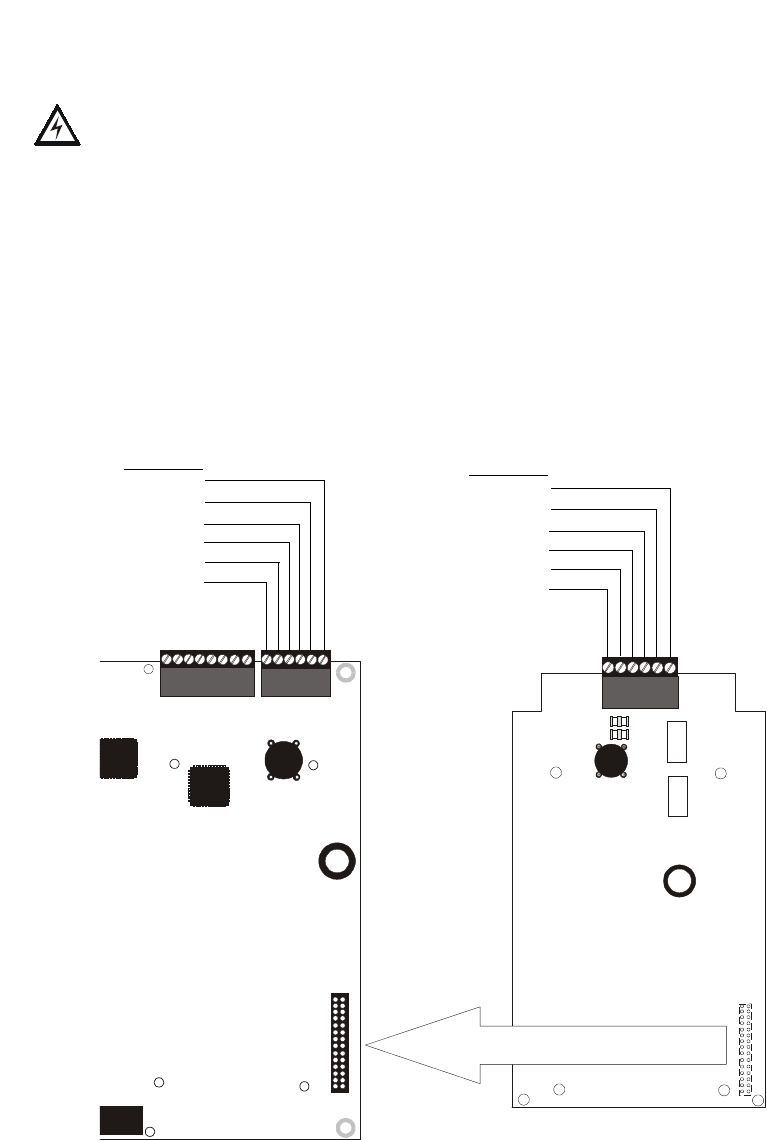
2SWLRQDO0RGXOHVDQG'HYLFHV ,QVWDOODWLRQ
8QLPRGH31&
2.6.3 SLC-2 Expander Module
The optional SLC-2 Expander Module provides a second SLC loop for the Unimode 9600
control panel. This allows connection of an additional 318 addressable devices, bringing
the total to 636 addressable devices which can be connected to the FACP. Refer to the
SLC Manual for information on connecting devices to the SLC.
The following steps must be followed when installing the SLC-2 Expander Module:
1. Remove all power (AC and DC) from the FACP before installing the SLC-2 module
2. Carefully plug connector J3 on the SLC-2 module into connector J3 on the
Unimode 9600 main circuit board, being careful not to bend any pins
3. Secure the SLC-2 Expander Module to the four standoffs on the FACP main circuit
board with the supplied screws
4. Connect the SLC wiring and devices to TB8 on the SLC Expander Module. Refer
to the SLC Manual for wiring information
5. Reapply power to the control panel
6. Program the addressable devices connected to the SLC-2 Expander Module as
detailed in "Master Programming Level" on page 42
7. Test the system for proper operation
Reference
Manual
See Page
J3
J3
OPT SLC
TB7 TB8 TB8
Figure 2.11 SLC-2 Expander Module Installation
SLC-2 Expander Module
Unimode 9600
SLC Loop 2
Shield B
Shield A
SLC A-
SLC B-
SLC A+
SLC B+
SLC Loop 1
Shield B
Shield A
SLC A-
SLC B-
SLC A+
SLC B+
96optslc.cdr
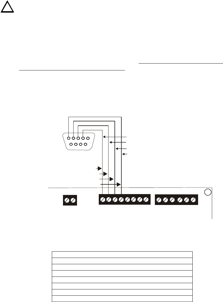
,QVWDOODWLRQ 2SWLRQDO0RGXOHVDQG'HYLFHV
8QLPRGH31&
2.6.4 Printer/PC
A serial printer or a PC (personal computer) may be connected to TB7 Terminals 1 - 4 on
the FACP. The printer can be used to provide a hard-copy printout of real-time events,
history file and walktest data. An IBM compatible PC can be connected to provide local
FACP programming capabilities using the PK-9600 programming utility. Installation of
either device requires panel programming to allow the FACP to communicate with the
device.
CAUTION! Do not connect a printer or PC to the Unimode 9600 FACP if a ground fault
exists on the control panel. Circuit damage may result. Remove all power (AC and DC)
before installing or removing any wiring.
Installation
Remote printers and PCs require separate primary power. Also required is the PRT/
PK-CABLE which is an interface cable prewired to a DB9F connector. Wire the PRT/PK-
CABLE to TB7 Terminals 1 - 4 as illustrated in the following figure. Connect the DB9F
connector to the printer or PC serial EIA-232 port. If a nine-pin serial connector is not
available on the printer or PC, use a DB25 adapter. Make certain that the DB25 adapter
does not swap the Transmit and Receive lines. Apply power to the FACP and printer or
PC. Note that a ground fault may occur on the FACP, dependent on the printer or PC
being used, due to this connection. For this reason, it is important that there be no
preexisting ground fault on the panel.
Note that the printer may or may not be supervised as determined by user programming.
Refer to "Printer/PC" on page 92.
Printer Configuration
Refer to the documentation supplied with the printer for pertinent information about
printer setup. Set the printer’s options as listed in the following table:
PC Configuration
The Windows-based PK-9600 Programming Utility Kit contains CD-ROM with on-line
help file.
COMMUNICATION SETUP
BUFFER: LARGE
DATA BITS: 7
PARI T Y: E V E N
STOP BIT: 1 STOP
BAUD RATE: 2400/4800/9600
AUTOMATIC LINE FEED NO
AUTOMATIC CARRIAGE RETURN NO
!
RS-232 PC/PRINTER
B+ A+ B- A- B A
1 COMM 2
ACS SHIELD
SLC SLC
XMT RCV DTR GRND
T
B
7
T
B
6
T
B
8
Black
RCV
DTR
GRND
TX
5 4 3 2 1
9 8 7 6
White
Green
Red
Figure 2.12 Serial Printer and Computer Connections
PRT/PK-CABLE
9600tb7a.cdr
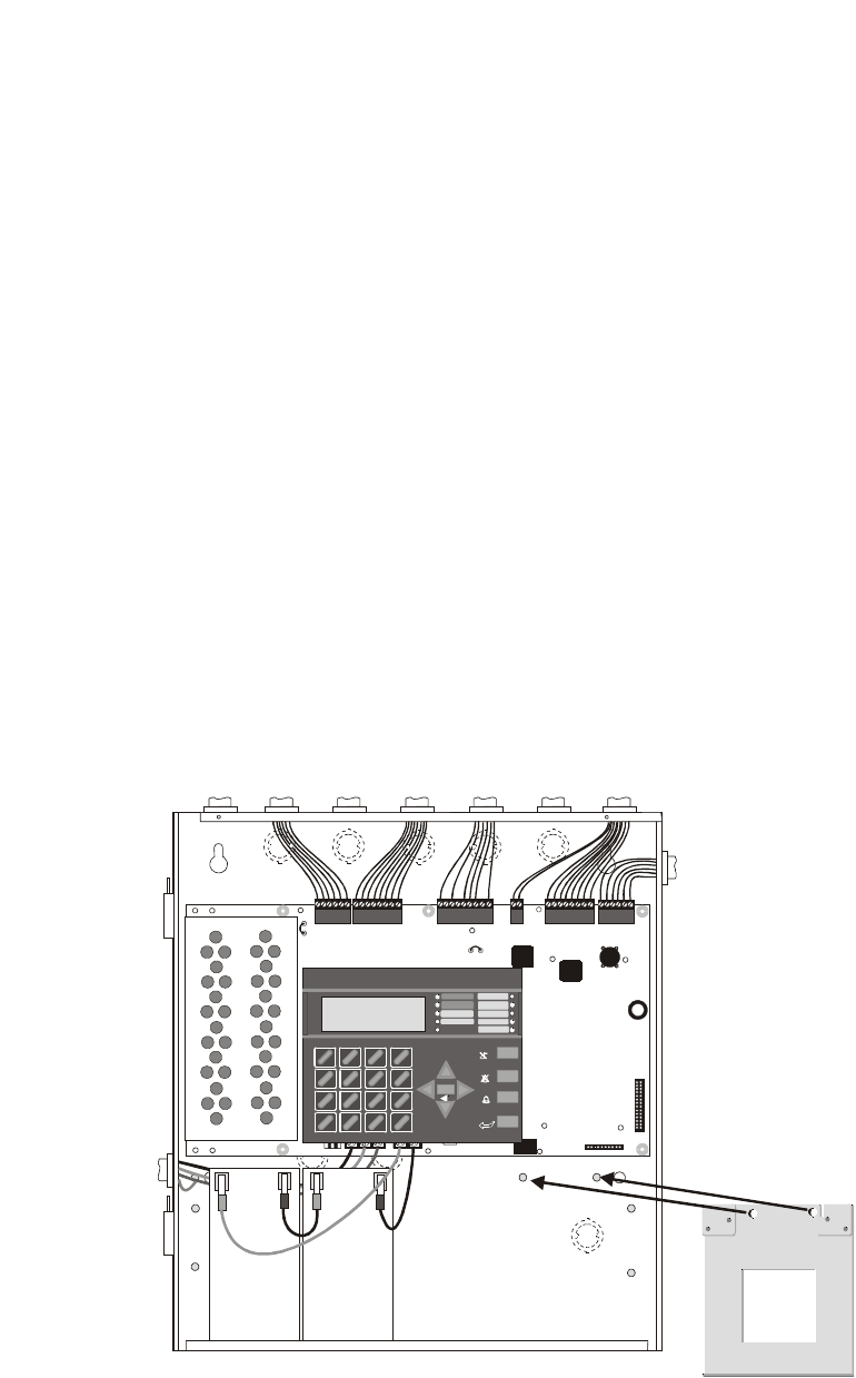
2SWLRQDO0RGXOHVDQG'HYLFHV ,QVWDOODWLRQ
8QLPRGH31&
2.6.5 Digital Communicator and Annunciators
2.6.5.1 ADT-UDACT Digital Alarm Communicator/Transmitter
7KH$'78'$&7WUDQVPLWVV\VWHPVWDWXVWR8/OLVWHG&HQWUDO6WDWLRQUHFHLYHUVYLD
WKHSXEOLFVZLWFKHGWHOHSKRQHQHWZRUN,WLVFDSDEOHRIUHSRUWLQJXSWRVRIWZDUH
]RQHVRUXSWRDGGUHVVDEOHSRLQWV7KH$'78'$&7FDQEHPRXQWHGUHPRWHO\LQ
D8%6)RU$'7$%65)HQFORVXUHRULQWKHSDQHOFDELQHWXVLQJWKH31%5.7
8QLYHUVDO%UDFNHWUHIHUWR$'78'$&70DQXDO7KH8QLPRGHLV
FRPSDWLEOHZLWK$'78'$&7VRIWZDUH8'$&7DQGDERYH
3URJUDPPLQJ
7KH8QLPRGHPXVWEHSURJUDPPHGWRRSHUDWHZLWKWKH$'78'$&75HIHUWR
$QQXQFLDWRUV8'$&7RQSDJHIRUFRQWUROSDQHOSURJUDPPLQJLQIRUPDWLRQ
2.6.5.2 ADT-ACM-8R Relay Control Module
7KH$'7$&05PRGXOHSURYLGHVHLJKW)RUP&UHOD\VZLWKFRQWDFWVUDWHGIRU
DPSV:KHQLQVWDOOHGZLWKDQ8QLPRGH)$&3WKH$'7$&05PRGXOHV
SURYLGHUHOD\DFWLYDWLRQIRUHDFKRIWKHSRVVLEOH)$&3]RQHVSOXVVSHFLDOIXQFWLRQV
2SWLRQVH[LVWWRDOORZIRUDODUPRQO\RUDODUPDQGWURXEOHDFWLYDWLRQSHU]RQH2XWSXW
DFWLYDWLRQIRUJHQHUDODODUPJHQHUDOWURXEOHJHQHUDOVXSHUYLVRU\1$&IDXOW$&IDLO
ZDONWHVWVWDUWDQGEDWWHU\WURXEOHDUHDOVRDYDLODEOH7KH$'7$&05FDQEH
PRXQWHGUHPRWHO\LQDQ$'7$%65)DQQXQFLDWRUVXUIDFHPRXQWEDFNER[RULQWKH
SDQHOFDELQHWXVLQJWKH31%5.78QLYHUVDO%UDFNHW5HIHUWRWKH$'7$&0
5PDQXDOIRULQIRUPDWLRQRQVHWWLQJPRGXOHVZLWFKHVIRUDGGUHVVLQJDQGUHOD\
IXQFWLRQV
2.6.5.3 BRKT-9600 Universal Bracket Installation
7KHRSWLRQDO%5.78QLYHUVDO%UDFNHWFDQEHXVHGWRPRXQWVSHFLILFPRGXOHV
LQVLGHWKH8QLPRGHFDELQHW7KH%5.7PRXQWVWRWZRVWXGVORFDWHGLQWKH
ORZHUULJKWFRUQHURIWKHFRQWUROSDQHOFDELQHWDVLOOXVWUDWHGEHORZ,WLVVHFXUHGWRWKH
3(0VWXGVRQWKHEDFNZDOORIWKHFDELQHWZLWKWZRVXSSOLHGKH[QXWV
,03257$17:KHQWKH%5.7LVLQVWDOOHGWKH8QLPRGHFDELQHWFDQ
KROGDPD[LPXPRIWZR$PS+RXUEDWWHULHVZLWKWKHRULHQWDWLRQLOOXVWUDWHGEHORZ
Reference
Manual
See Page
Reference
Manual
+BATTERY-
LCD DISPLAY KEYPAD I/F
1
2
3
OPT DACT
HOT
CB1
J3
J12
J2
TB1 TB2
TB3
JP3
JP2
JP8
JP4
JP7
JP5
JP6
J17 J16
J6 J8
J7
JP10 JP11
CUT TO
DISA BLE
LOCAL
CHARG ER
DISA BLE
GND
FLT
CUT TO
MONITOR 4XTM
OPT SLC
4XTM OPT BD
TB4 TB5 TB6 TB7 TB8
NEUT E ARTH
1
4
*
2
5
0
3
6
#
1
st
EVENT
ABC DEF
GHI JKL MNO
PRS TUV WXY
QZ
-/.
CLR
78 9
ESC
ENTER
RECALL
ACK/STEP
ALARM
SILENC E
DRILL
HOLD 2 SEC
RESET
MODE
MAI NT EN ANC E
GROUND
BATTERY
DISABLED
ALA RM
SILENCED
TROUBLE
SUPERVISORY
FIRE ALARM
AC POWER
Figure 2.13 BRKT-9600 Bracket Installation
Mount BRKT-9600 to PEM
studs on back of cabinet
using supplied hex nuts.
Unimode 9600 Cabinet
96brkmnt.cdr
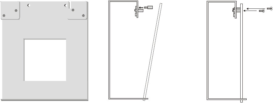
,QVWDOODWLRQ 2SWLRQDO0RGXOHVDQG'HYLFHV
8QLPRGH31&
0RGXOH,QVWDOODWLRQRQ%5.7
7KHIROORZLQJPRGXOHVFDQEHLQVWDOOHGLQVLGHWKH8QLPRGHFDELQHWXVLQJWKH
%5.78QLYHUVDO%UDFNHW
✓ADT-UDACT Digital Alarm Communicator/Transmitter - installs at standoff
location (A)
✓ADT-ACM-8R Annunciator Control Module (Relay) - installs at standoff
location (A)
5HIHUWRWKHDSSURSULDWHPRGXOHPDQXDOIRUGHWDLOHGLQIRUPDWLRQRQPRGXOHRSHUDWLRQ
DQGZLULQJ
1. Install the two supplied standoffs in location (A) as indicated in Step 1 of the
following illustration
2. Position the module bottom in the slot located in the bottom of the BRKT-9600 as
indicated in Step 2 of the following illustration
3. Secure the module to the standoffs installed in the top of the BRKT-9600 with two
mounting screws as indicated in Step 3 of the following illustration
4. Refer to the appropriate module manual for detailed information on wiring the
module for power, communication, etc.
5. Install a maximum of two 12 Amp Hour batteries with the orientation illustrated in
Figure 2.13. Larger batteries require a separate UL listed battery box
1RWH'RQRWEULQJZLULQJRUFRQGXLWLQWRWKHERWWRPRIWKHFDELQHWIRUWKLV
DSSOLFDWLRQ
Figure 2.14 BRKT-9600 Module Installation Steps
Step 1 Step 2 Step 3
(A) (A)
Slot
module module
BRKT-9600 BRKT-9600 BRKT-9600
mounting
screws
standoffs
96brcksd.cdr
9600brkt.cdr

2SWLRQDO0RGXOHVDQG'HYLFHV ,QVWDOODWLRQ
8QLPRGH31&
2.6.5.4 ADT-ACS and ADT-AFM Series Annunciators
$'7$&6DQG$'7$)06HULHV$QQXQFLDWRUVSURYLGHYLVXDOLQGLFDWLRQVRI)$&3
VWDWXVLQUHPRWHORFDWLRQV5HIHUWRWKHDSSURSULDWHDQQXQFLDWRUPDQXDOIRU
LQIRUPDWLRQRQLQVWDOODWLRQZLULQJDQGRSHUDWLRQ
$'7$&6DQQXQFLDWRUDGGUHVVLQJLVVSHFLILFWRWKH8QLPRGHFRQWUROSDQHO7KH
IROORZLQJWDEOHGHVFULEHVWKH$'7$&6DQQXQFLDWRUDGGUHVVHVDQGWKHFRUUHVSRQGLQJ
DGGUHVVDEOHGHYLFHVWKDWZLOOEHDQQXQFLDWHGDWHDFKDQQXQFLDWRUDGGUHVV
,PSRUWDQW,ID$'78'$&7LVLQVWDOOHGLQWKH8QLPRGHDQGVHOHFWHGLQ
SURJUDPPLQJWKHFRQWUROSDQHOZLOODXWRPDWLFDOO\DVVLJQDQQXQFLDWRUDGGUHVVHV
WRWKH$'78'$&7DQGGLVDEOHWKHVHOHFWLRQRIWKHVHDGGUHVVHVLQSURJUDPPLQJIRU
$'7$&6DQQXQFLDWRUV'RQRWVHWDQ\$'7$&6DQQXQFLDWRUVWRWKHVHDGGUHVVHV
7KH8QLPRGHPXVWEHSURJUDPPHGIRUWKHDQQXQFLDWRUVLQVWDOOHGRQWKHV\VWHP
5HIHUWR$QQXQFLDWRUV8'$&7RQSDJHIRULQIRUPDWLRQRQ$'78'$&7DQG
DQQXQFLDWRUSURJUDPPLQJ0DNHFHUWDLQWRSURJUDPWKHDQQXQFLDWRUDGGUHVVHVWKDW
KDYHEHHQSK\VLFDOO\LQVWDOOHGRQWKHV\VWHP
1RWH7KH*HQHUDO6\VWHP6WDWXV3RLQWVLQFOXGHWKHIROORZLQJ
• General Alarm
• General Trouble
• General Supervisory
• Alarm Silenced
• System Off Normal
•AC Loss
• Battery Fault
• NAC Fault
ADT-ACS Annunciator Address Annunciator Displays the Following Points
1 8 General System Status Points & Zones 1 - 56
2 Zones 57 - 99 & 2 NACs
3 Loop 1, Module Addresses 1 - 64
4 Loop 2, Module Addresses 1 - 64
5 Loop 1, Module Addresses 65 - 128
6 Loop 2, Module Addresses 65 - 128
7 Loop 1, Module Addresses 129 - 159 & Loop 2 Module Addresses 129 - 159
8 Loop 1, Detector Addresses 1 - 64
9 Loop 2, Detector Addresses 1 - 64
10 Loop 1, Detector Addresses 65 - 128
11 Loop 2, Detector Addresses 65 - 128
12 Loop 1 Detector Addresses 129 - 159 & Loop 2 Detector Addresses 129 - 159
13 not used
14 not used
15 not used
16 not used
17 not used
18 not used
19 not used
20 8 General System Status Points & Zones 1 - 56
21 Zones 57 - 99 & 2 NACs
22 Loop 1, Module Addresses 1 - 64
23 Loop 2, Module Addresses 1 - 64
24 Loop 1, Module Addresses 65 - 128
25 Loop 2, Module Addresses 65 - 128
26 Loop 1, Module Addresses 129 - 159 & Loop 2 Module Addresses 129 - 159
27 Loop 1, Detector Addresses 1 - 64
28 Loop 2, Detector Addresses 1 - 64
29 Loop 1, Detector Addresses 65 - 128
30 Loop 2, Detector Addresses 65 - 128
31 Loop 1 Detector Addresses 129 - 159 & Loop 2 Detector Addresses 129 - 159
32 not used

3URJUDPPLQJ 3URJUDPPLQJ'DWD(QWU\
8QLPRGH31&
SECTION 3 Programming
3.1 Programming Data Entry
Programming can be accomplished using the Unimode 9600 keypad or by connecting an
optional standard computer keyboard. The keyboard can be connected to the PS-2
connector J7 on the control panel main circuit board.
The information presented in this section refers to programming the Unimode 9600 via the
onboard keypad. If an optional computer keyboard is connected to the Unimode 9600
main circuit board, the following table describes the keyboard keys which correspond to
the onboard keypad keys.
Note: The main keypad function keys (ACK/STEP, ALARM SILENCE, DRILL and RESET)
are not available on the keyboard.
Keypad Keys Computer Keyboard Keys
1st Event Home
CLR Delete
ESC Esc
RECALL Insert
**
##
A - Z A - Z
0 - 9 0 - 9
(on QZ key) Space bar
——
//
••
ENTER Enter

8VHU3URJUDPPLQJ 3URJUDPPLQJ
8QLPRGH31&
3.2 User Programming
The Unimode 9600 is completely field programmable and requires no special software
skills. While programming the Unimode 9600, the fire protection capabilities of the
control panel are enabled.
Site-specific programming may be accomplished in three ways:
•Autoprogramming Feature - This is a convenient method for quickly bringing the
FACP addressable SLC devices on-line without the necessity of programming each
device individually. Refer to "Autoprogram" on page 87 for a detailed description
of Autoprogramming
• Manual programming or editing, using the FACP keypad or a PC keyboard
• Off-line Programming and Editing Feature - allows creation and editing of site-
specific custom programs using a Windows-based computer. For programs
requiring a large amount of data entry, this method may be preferred. A PK-9600
programming kit can be ordered for this purpose
The System All Normal screen will be displayed in a programmed system with no active
alarms, troubles or supervisories, as illustrated below:
Programming and Read Status mode can be entered while the panel is in any mode of
operation. If the panel is in alarm, the alarm condition must be acknowledged before
entering other modes. To access any of the programming or read status features, the Enter
or Mode key must be pressed, which will cause the LCD to display the following:
Pressing 1, while this screen is being displayed, will cause the control panel to enter the
Read Status feature which allows the user to view the programmed features and status of
the control panel The Read Status feature is not password protected. Refer to "Read
Status" on page 117 for a detailed description of this feature.
Pressing 2 will select user Programming which may only be accomplished by an
authorized person. After pressing 2, a screen will prompt for a password. After entering
the correct password, the user may select from a list of programming options.
Exit Programming or Read Status
The programmer can exit Read Status or Programming mode by repeatedly pressing the
keypad ESC (Escape) key until the display reads System All Normal. Note that the data
which is entered during Programming mode is not saved until the programmer exits this
mode by repeatedly pressing the ‘ESC’ key. If the Reset key is pressed or power is lost
before exiting Programming mode, all data which was just entered will be lost.
!
!
!
SYSTEM@ALL@NORMAL
10:00A@010801
1=READ@STATUS
2=PROGRAMMING
See Page

3URJUDPPLQJ ,QLWLDO3RZHUXS
8QLPRGH31&
User Programming Levels
There are two user programming levels:
• User Master Program Level 1 is used for programming panel specific data relating
to device types, zoning, messages, control panel functions, etc.
• User Maintenance Program Level 2 is used by a qualified operator to access
features such as Disable/Enable, View and Clear History, Walktest and System
Time Change.
3.3 Initial Power-up
The following sections describe the initial programming procedures for a new system.
The same procedures are used to modify programming in an existing system.
After completing the wiring of addressable devices to the SLC, apply power to the control
panel. If the addressable devices have not yet been programmed into the FACP, their
LEDs will not flash and the following trouble message will be displayed.
3.4 Programming Screens Description
Two main options are available when the Enter key is pressed: Read Status and
Programming. Each option has multiple functions or features which may be chosen. To
view all of the choices, it is necessary that the programmer scroll through a number of
additional subscreens. These selections are displayed on multiple screens to make them
more readable for the programmer. Refer to "Master Programming Level" on page 42, for
additional information on the various screens.
The title of the main option screen will always be displayed at the top of the subscreens for
the programmer’s convenience. If additional subscreens exist, an Up or Down arrow will
be displayed in the upper right corner of the screen being viewed. The programmer can
then press the keypad Up or Down arrow key to view the new subscreen. To select one of
the choices in a screen, the programmer presses the keypad numerical key corresponding
to the desired choice.
Note that subscreens may also have multiple options which require viewing more than one
screen. The same process, as detailed in the previous paragraphs, is followed to view all
option choices.
3.5 Programming and Passwords
There are two factory set programming passwords which will access the Programming
screens as indicated in the following examples. From either of the screens, access to
specific system and device features or programming may be obtained. All user
programming entries are stored in nonvolatile memory. The factory set passwords can be
changed by the user as described in "Password Change" on page 93. If an invalid
password is entered, the blinking cursor will return to the first password character
position. To exit Programming or Read Status mode at any time, press the ESC (Escape)
key repeatedly. Note that Programming mode must be exited using the ESC key in order
to store the program data entered during this mode. If the Reset key is pressed or power is
lost before exiting Programming mode, the data just entered will not be saved.
TROUBL@IN@SYSTEM
NO@DEVICES@INSTALLED
09:03A@010801
See Page
See Page

3URJUDPPLQJDQG3DVVZRUGV 3URJUDPPLQJ
8QLPRGH31&
To access user Programming mode, press the Enter or Mode key. The LCD will display
the following:
To enter the user Programming mode, press 2. The display will read as follows:
Entering the Master level password (default 00000) will cause the following screen to
appear:
If the Maintenance level password (default 11111) is entered, the following screen will
appear:
Note that in the two preceding screens, an arrow appears to inform the programmer that
additional options can be viewed by pressing the keypad down arrow key.
1=READ@STATUS
2=PROGRAMMING
PROGRAMMING
ENTER@PASSWORD
*****
@@@@PROGRAMMING
1=POINT@PROGRAM
2=ZONE@SETUP
3=LOOP@SETUP
@@@@PROGRAMMING
1=POINT PROGRAM
2=HISTORY
3=PROGRAM CHECK

3URJUDPPLQJ 0DVWHU3URJUDPPLQJ/HYHO
8QLPRGH31&
3.6 Master Programming Level
When the Master Program Level password is entered, the control panel will enter user
Programming mode. In this mode, the piezo sounder remains off, the trouble relay is
activated and the system Trouble LED flashes until Programming mode is exited. The
following display will appear:
The down arrow which appears in the display indicates that additional programming
choices can be viewed by pressing the down arrow key on the keypad. If a down and up
arrow appear in the display, pressing the ‘down’ arrow key will display the subsequent
Programming Screens as illustrated below while pressing the ‘up’ arrow key will display
the previous screen.
@@@@PROGRAMMING
1=POINT@PROGRAM
2=ZONE@SETUP
3=LOOP@SETUP
Programming Screen #1
@@@@PROGRAMMING
1=SYSTEM@SETUP
2=AUTOPROGRAM
3=VERIFY@LOOPS
@@@@PROGRAMMING
1=HISTORY
2=WALKTEST
3=OPTION@MODULES
@@@@PROGRAMMING
1=PASSWORD@CHANGE
2=CLEAR@PROGRAM
3=PROGRAM@CHECK
Programming Screen #2
Programming Screen #3
Programming Screen #4

0DVWHU3URJUDPPLQJ/HYHO 3URJUDPPLQJ
8QLPRGH31&
3.6.1 Point Program
The Point Program option allows the programmer to add a new addressable device to an
SLC loop, delete an existing device from a loop or change the programming for an
existing device. Pressing 1, while viewing Programming Screen #1, will select the Point
Program option and display the following screen:
The programmer selects the desired SLC loop by pressing 1 or 2 in Point Program Screen
#1, which causes the panel to display the following screen:
3.6.1.1 Detector Programming
3UHVVLQJZKLOHYLHZLQJ3RLQW3URJUDP6FUHHQZLOODOORZWKHSURJUDPPHUWRDGG
GHOHWHRUFKDQJHWKHSURJUDPPLQJRIDQDGGUHVVDEOHGHWHFWRU7KHIROORZLQJVFUHHQ
ZLOOEHGLVSOD\HGE\WKHFRQWUROSDQHO
3.6.1.1.1 Add Detector
3UHVVLQJZKLOHYLHZLQJWKH'HWHFWRU6FUHHQZLOOGLVSOD\WKHIROORZLQJVFUHHQZKLFK
DOORZVWKHSURJUDPPHUWRDGGDQHZGHWHFWRUDGGUHVVWRSURJUDPPLQJ
$IODVKLQJFXUVRUZLOODSSHDULQWKHSRVLWLRQRIWKHILUVWDVWHULVNWRWKHOHIW7KH
SURJUDPPHUNH\VLQWKHWKUHHGLJLWGHWHFWRUDGGUHVVVXFKDV
PROGRAMMING
1=POINT PROGRAM
2=ZONE SETUP
3=LOOP SETUP
Programming Screen #1
@@@POINT@PROGRAM
@@@@SELECT@LOOP
1=LOOP@1
2=LOOP@2
Point Program Screen #1
@@@POINT@PROGRAM
@@@@SELECT@TYPE
1=DETECTOR
2=MODULE
Point Program Screen #2
@@@@@@DETECTOR
1=ADD
2=DELETE
3=EDIT
Detector Screen
@@@@ADD@DETECTOR
ENTER@DETECTOR#
***
Add Detector Screen

3URJUDPPLQJ 0DVWHU3URJUDPPLQJ/HYHO
8QLPRGH31&
:KHQWKHODVWGLJLWLVNH\HGLQWKHIROORZLQJVFUHHQZLOOEHGLVSOD\HG
7KHSURJUDPPHUFDQFRQWLQXHDGGLQJGHWHFWRUVE\SUHVVLQJWKH(6&RUOHIWDUURZNH\
ZKLFKZLOOUHWXUQWKHGLVSOD\WRWKH$GG'HWHFWRU6FUHHQ
3.6.1.1.2 Delete Detector
3UHVVLQJLQWKH'HWHFWRU6FUHHQZLOOGLVSOD\WKH'HOHWH'HWHFWRU6FUHHQZKLFKDOORZV
WKHSURJUDPPHUWRGHOHWHDVSHFLILFGHWHFWRU
$IODVKLQJFXUVRUZLOODSSHDULQWKHSRVLWLRQRIWKHILUVWDVWHULVNWRWKHOHIW7KH
SURJUDPPHUNH\VLQWKHWKUHHGLJLWGHWHFWRUDGGUHVVVXFKDV:KHQWKHODVWGLJLW
LVNH\HGLQWKHIROORZLQJVFUHHQZLOOEHGLVSOD\HG
7KHSURJUDPPHUFDQFRQWLQXHGHOHWLQJGHWHFWRUVE\SUHVVLQJWKH(6&RUOHIWDUURZNH\
ZKLFKZLOOUHWXUQWKHGLVSOD\WRWKH'HOHWH'HWHFWRU6FUHHQ
3.6.1.1.3 Edit Detector
TKHSURJUDPPHUFDQFKDQJHDGHWHFWRUVH[LVWLQJRUIDFWRU\GHIDXOWSURJUDPPLQJE\
SUHVVLQJLQWKH'HWHFWRU6FUHHQ7KHIROORZLQJVFUHHQZLOOEHGLVSOD\HG
$IODVKLQJFXUVRUZLOODSSHDULQWKHSRVLWLRQRIWKHILUVWDVWHULVNWRWKHOHIW7KH
SURJUDPPHUNH\VLQWKHWKUHHGLJLWGHWHFWRUDGGUHVVVXFKDV
@@@@ADD@DETECTOR
DETECTOR#@@@@@@@005
IS@ADDED
DETECTOR
1=ADD
2=DELETE
3=EDIT
Detector Screen @@DELETE@DETECTOR
ENTER@DETECTOR#
***
Delete Detector Screen
@@DELETE@DETECTOR
DETECTOR#@@@@@@@005
IS@DELETED
@@EDIT@DETECTOR
ENTER@POINT@ADDRESS
***
Edit Detector Screen

0DVWHU3URJUDPPLQJ/HYHO 3URJUDPPLQJ
8QLPRGH31&
:KHQWKHODVWGLJLWLVNH\HGLQLIWKHVHOHFWHGDGGUHVVKDVQRWEHHQDGGHGWR
SURJUDPPLQJDVFUHHQVKRZLQJLQIRUPDWLRQDERXWDGHYLFHZLWKWKHKLJKHVWDGGUHVV
WKDWLVLQVWDOOHGZLOOEHGLVSOD\HG
,IQRGHWHFWRUVKDYHEHHQLQVWDOOHGRQWKHORRSWKHIROORZLQJZLOOEHGLVSOD\HG
,IWKHVHOHFWHGDGGUHVVKDVEHHQDGGHGWRSURJUDPPLQJGHYLFHVXPPDU\VFUHHQVZLOO
EHGLVSOD\HG7KHVHVFUHHQVDOORZWKHSURJUDPPHUWRYLHZDOOGHYLFHVHWWLQJVDWD
VLQJOHJODQFH3UHVVLQJWKHOHIWRUULJKWDUURZNH\VZLOODOORZWKHSURJUDPPHUWR
UDSLGO\YLHZWKHGHYLFHVDWWKHSUHYLRXVRUQH[WDGGUHVVLILQVWDOOHG
,IDGHWHFWRUVXFKDVDSKRWRHOHFWULFGHWHFWRUZLWKWKHVHOHFWHGDGGUHVVLVQRW
SK\VLFDOO\LQVWDOOHGRQWKH6/&RUKDVDFRPPXQLFDWLRQIDXOWEXWWKHDGGUHVVLV
SURJUDPPHGLQWKHV\VWHPWKHIROORZLQJVFUHHQZLOOEHGLVSOD\HG
,IWKHVHOHFWHGDGGUHVVKDVEHHQDGGHGWRSURJUDPPLQJDQGDGHWHFWRUVXFKDVD
SKRWRHOHFWULFGHWHFWRUZLWKWKHVHOHFWHGDGGUHVVLVSK\VLFDOO\LQVWDOOHGRQWKH6/&DQG
LVFRPPXQLFDWLQJZLWKWKHFRQWUROSDQHOWKHIROORZLQJZLOOEHGLVSOD\HG
7RFKDQJHWKHSURJUDPPLQJIRUWKHGLVSOD\HGGHWHFWRUSUHVVWKHNH\ERDUGµGRZQ
DUURZNH\WRYLHZWKH(GLW'HWHFWRUVFUHHQV
,QWKHSUHFHGLQJH[DPSOH
✓Normal - indicates that the detector with the selected address is physically
installed on the SLC and communicating with the control panel (enabled)
✓<ADJ><NOUN> - represents the adjective and noun, which have been
programmed, describing the location of the displayed device
✓ZNNN - represents the first of five possible software zones that the detector is
assigned to (NNN = the three digit zone number from 000 - 099)
✓V or * - indicates whether or not alarm verification is enabled (V = alarm
verification enabled and * = alarm verification disabled)
✓1D017 - represents the Loop, Device type and Device address (1 = SLC Loop 1,
D=Detector and 017 = Detector Address 017)
@@@@NO@DETECTOR
@@@@@INSTALLED
Edit Detector Screen #1
@TROUBL@SMOKE(PHOTO)
@********************
@@@@@@@@@@@@@@@ZNNN
@@@@@@@@@@@*@@@@1D017
Edit Detector Screen #1
@NORMAL@SMOKE@(PHOTO)
@*********************
@@@@@@@@@@@@@@@@ZNNN
@@@@@@@@@@@@@V@@@1D017
Edit Detector Screen #1

3URJUDPPLQJ 0DVWHU3URJUDPPLQJ/HYHO
8QLPRGH31&
7KHIROORZLQJH[DPSOHVVKRZWKHHGLWLQJRIDSKRWRHOHFWULFsmoke detector with
address 017, located on the first SLC loop:
(QDEOH'LVDEOH'HWHFWRU
7R(QDEOHRU'LVDEOHWKHGHWHFWRUSUHVVWKHNH\ZKLOHYLHZLQJWKH(GLW'HWHFWRU
6FUHHQ(DFKSUHVVRIWKHNH\ZLOOWRJJOHWKHVFUHHQEHWZHHQ(QDEOHG<HVDQG
(QDEOHG1R,I(QDEOHG1RLVVHOHFWHGWKHGHWHFWRUZLOOQRWEHSROOHGE\WKHFRQWURO
SDQHOSUHYHQWLQJWKHGHWHFWRUIURPUHSRUWLQJDODUPVDQGWURXEOHVWRWKHSDQHO7KH
FRQWUROSDQHOZLOOGLVSOD\WKHGHYLFHW\SHDQGDGGUHVVZKLFKKDVEHHQGLVDEOHGDQG
ZLOOWXUQRQWKH7URXEOH/('DQG'LVDEOH/('
EDIT@DETECTOR@1D017
1=ENABLED@@@@@@@@YES
2=TYPE@@SMOKE(PHOTO)
3=VERIFICATION@@@OFF
Edit Detector Screen #2
EDIT@DETECTOR@1D017
1=WALKTEST@@@@@@@@NO
2=PAS@@@@@@@@@@@@@NO
3=PRE-SIGNAL@@@@@@NO
Edit Detector Screen #3
EDIT@DETECTOR@1D017
1=ZONE@ASSIGNMENT
@@@@00@**@**@**@**
Edit Detector Screen #4
Edit Detector Screen #5
EDIT@DETECTOR@1D017
1=NOUN/ADJECTIVE
2=DESCRIPTION
********************
EDIT DETECTOR
1=ENABLED
2=TYPE
3=VERIFICATION
Edit Detector Screen #2

0DVWHU3URJUDPPLQJ/HYHO 3URJUDPPLQJ
8QLPRGH31&
7\SH
7RVHOHFWWKHW\SHRIGHWHFWRUEHLQJSURJUDPPHGSUHVVWKHNH\ZKLOHYLHZLQJWKH
(GLW'HWHFWRU6FUHHQ7KLVZLOOFDXVHWKHFRQWUROSDQHOWRGLVSOD\WKHIROORZLQJ
'HWHFWRU7\SH6FUHHQV
:KLOHYLHZLQJHLWKHU'HWHFWRU7\SHVFUHHQVHOHFWWKHW\SHRIGHWHFWRUEHLQJ
SURJUDPPHGE\SUHVVLQJWKHFRUUHVSRQGLQJNH\ERDUGQXPEHUNH\7KHGLVSOD\ZLOO
UHWXUQWR(GLW'HWHFWRU6FUHHQDQGLQGLFDWHWKHVHOHFWLRQQH[WWRWKH7\SHRSWLRQ
1RWH,IDGHWHFWRULVVHOHFWHGWREHD683(59'8&73W\SHLWZLOOIXQFWLRQOLNHD
VXSHUYLVRU\SRLQWQRWDILUHDODUPSRLQW7KHVXSHUYLVRU\/('DQGVXSHUYLVRU\UHOD\
ZLOODFWLYDWHQRWWKHILUHDODUP/('RUDODUPUHOD\LIWKHGHWHFWRUVHQVHVVPRNH
9HULILFDWLRQ
$ODUPYHULILFDWLRQLVXVHGWRFRQILUPWKDWDVPRNHGHWHFWRUDFWLYDWLRQLVDWUXHDODUP
FRQGLWLRQDQGQRWDIDOVHDODUP7KLVIHDWXUHLVVHOHFWHGE\SUHVVLQJZKLOHYLHZLQJ
WKH(GLW'HWHFWRU6FUHHQVRWKDWWKHGLVSOD\UHDGV9HULILFDWLRQ2Q(DFKWLPHWKH
NH\LVSUHVVHGWKHGLVSOD\ZLOOWRJJOHEHWZHHQ9HULILFDWLRQ2QDQG9HULILFDWLRQ2II
)RUDGHWDLOHGGHVFULSWLRQUHIHUWR$ODUP9HULILFDWLRQ1RQHRU7ZR0LQXWHVRQ
SDJH
:DONWHVW
7KH:DONWHVWIHDWXUHDOORZVRQHSHUVRQWRWHVWWKHV\VWHPGHYLFHVZLWKRXWWKHQHFHVVLW\
RIPDQXDOO\UHVHWWLQJWKHFRQWUROSDQHODIWHUHDFKGHYLFHDFWLYDWLRQ7RHQDEOHDGHYLFH
IRUWKH:DONWHVWIHDWXUHSUHVVZKLOHYLHZLQJWKH(GLW'HWHFWRU6FUHHQXQWLOWKH
GLVSOD\UHDGV:DONWHVW<HV(DFKSUHVVRIWKHNH\ZLOOFDXVHWKHGLVSOD\WRWRJJOH
EHWZHHQ:DON WHVW <HVDQG:DONWHVW1R5HIHUWR:DONWHVWRQSDJH
3$6
7KH3$63RVLWLYH$ODUP6HTXHQFHRSWLRQZLOOSURJUDPWKHGHWHFWRUWRGHOD\SDQHO
DFWLYDWLRQLQFOXGLQJDODUPUHOD\DQGFRPPXQLFDWRUIRUDSHULRGRIVHFRQGVSOXVD
SURJUDPPDEOHWLPHRIXSWRPLQXWHV=RQHKRZHYHUZLOODFWLYDWHLPPHGLDWHO\
DQGPD\EHXVHGWRFRQQHFWDVLJQDOLQJGHYLFHWRLQGLFDWH3$6DFWLYDWLRQGRQRW
DVVLJQ=RQHWRD1RWLILFDWLRQ$SSOLDQFH&LUFXLWZKHQXVLQJWKLV]RQHWRLQGLFDWHD
3$6FRQGLWLRQ7RHQDEOHWKH3$6IHDWXUHSUHVVZKLOHYLHZLQJWKH(GLW'HWHFWRU
6FUHHQXQWLOWKHGLVSOD\UHDGV3$6<HV(DFKSUHVVRIWKHNH\ZLOOFDXVHWKH
GLVSOD\WRWRJJOHEHWZHHQ3$6<HVDQG3$61R5HIHUWR3RVLWLYH$ODUP6HTXHQFH
RQSDJH
EDIT DETECTOR
1=ENABLED
2=TYPE
3=VERIFICATION
Edit Detector Screen #2 @@@DETECTOR@TYPE
1=SMOKE(PHOTO)
2=SMOKE@(ION)
3=HEAT
Detector Type Screen #1
@@@DETECTOR@TYPE
1=SMOKE-DUCT-P
2=SUPERV@DUCTP
Detector Type Screen #2
See Page
EDIT DETECTOR
1=WALKTEST
2=PAS
3=PRE-SIGNAL
Edit Detector Screen #3
See Page

3URJUDPPLQJ 0DVWHU3URJUDPPLQJ/HYHO
8QLPRGH31&
)RUH[DPSOHLIDGHWHFWRUZLWKDGGUHVVLVWREHFRQILJXUHGIRU3$6RSHUDWLRQ
✓Select PAS Yes when editing the detector set to address 005
✓Program the desired zone or zones to be activated by this detector, in this
example Z001
✓Program an output, such as a control module that is to be activated by detector
005 by assigning the same zone to it; in this example Z001
✓Program an output, such as a control module, for PAS activation by assigning
zone Z97 to it. This control module may be connected to a signaling device used
to indicate a PAS condition. 'RQRWDVVLJQ=RQHWRD1RWLILFDWLRQ$SSOLDQFH
&LUFXLWZKHQXVLQJWKLV]RQHWRLQGLFDWHD3$6FRQGLWLRQ
✓Enable zones Z001 and Special Purpose Zone PAS 97 and set the PAS delay
timer to some value
:LWKWKHSUHFHGLQJSURJUDPVHWWLQJVZKHQWKHGHWHFWRUZLWKDGGUHVVLVDFWLYDWHG
]RQH=ZLOOFDXVHLWVDVVRFLDWHGFRQWUROPRGXOHWRDFWLYDWHLPPHGLDWHO\VRXQGLQJ
WKHFRQQHFWHG3$6VLJQDOLQJGHYLFH)ROORZLQJWKH3$6GHOD\WLPH]RQH=ZLOO
FDXVHLWVDVVRFLDWHGFRQWUROPRGXOHWRDFWLYDWHDQGWKHFRQWUROSDQHOZLOOLQLWLDWHDQ
DODUPFRQGLWLRQ
3UHVLJQDO
7KH3UHVLJQDORSWLRQSURJUDPVWKHGHWHFWRUWRGHOD\SDQHODFWLYDWLRQIRUD
SUHSURJUDPPHGWLPHGHOD\RIXSWRWKUHHPLQXWHVZKLOHDOORZLQJIRUYLVXDO
YHULILFDWLRQE\DSHUVRQ1RWHWKDWWKHDODUPUHOD\DQGFRPPXQLFDWRUZLOOUHVSRQGWR
WKHLQLWLDODODUPLPPHGLDWHO\,QDGGLWLRQ=RQHZLOODFWLYDWH7KLV]RQHFDQEH
SURJUDPPHGWRDFRQWUROPRGXOHZKLFKPD\EHXVHGWRDFWLYDWHDVRXQGHURULQGLFDWRU
ZKLFKWKHLQVWDOOHUGHVLJQDWHVDVD3UHVLJQDOLQGLFDWLRQGRQRWXVHD1RWLILFDWLRQ
$SSOLDQFH&LUFXLWIRUWKLVSXUSRVHTo enable the Pre-signal feature, press 3 while
viewing Edit Detector Screen #3 until the display reads Pre-signal Yes. Each press of
the 3 key will cause the display to toggle between Pre-signal Yes and Pre-signal No.
Refer to 3UHVLJQDORQSDJH.
)RUH[DPSOHLIDGHWHFWRUZLWKDGGUHVVLVWREHFRQILJXUHGIRU3UH6LJQDO
RSHUDWLRQ
✓Select Pre-signal Yes when editing the detector set to address 005
✓Program the desired zone or zones to be activated by this detector, in this
example Z001
✓Program an output, such as a control module that is to be activated by detector
005 by assigning the same zone to it; in this example Z001
✓Program an output, such as a control module, for Pre-signal activation by
assigning zone Z98 to it. This control module may be connected to a signaling
device used to indicate a Pre-signal condition GRQRWXVHD1RWLILFDWLRQ
$SSOLDQFH&LUFXLWIRUWKLVSXUSRVH
✓Enable zones Z001 and Special Purpose Zone Pre-signal 98 and set the Pre-signal
delay timer to some value
:LWKWKHSUHFHGLQJSURJUDPVHWWLQJVZKHQWKHGHWHFWRUZLWKDGGUHVVLVDFWLYDWHG
]RQH=ZLOOFDXVHLWVDVVRFLDWHGFRQWUROPRGXOHWRDFWLYDWHLPPHGLDWHO\VRXQGLQJ
WKHFRQQHFWHGVLJQDOLQJGHYLFHWRLQGLFDWHWKH3UHVLJQDOFRQGLWLRQ)ROORZLQJWKH3UH
VLJQDOGHOD\WLPH]RQH=ZLOOFDXVHLWVDVVRFLDWHGFRQWUROPRGXOHWRDFWLYDWHDQG
WKHFRQWUROSDQHOZLOOLQLWLDWHDQDODUPFRQGLWLRQ
EDIT DETECTOR
1=WALKTEST
2=PAS
3=PRE-SIGNAL
Edit Detector Screen #3
See Page

0DVWHU3URJUDPPLQJ/HYHO 3URJUDPPLQJ
8QLPRGH31&
=RQH$VVLJQPHQW
$PD[LPXPRIILYH]RQHVFDQEHSURJUDPPHGWRHDFKDGGUHVVDEOHGHWHFWRU3UHVVLQJ
ZKLOHYLHZLQJ(GLW'HWHFWRU6FUHHQGLVSOD\VWKHIROORZLQJVFUHHQ
1RWHWKDW=UHSUHVHQWVWKH=RQH1XPEHUVFRUUHVSRQGLQJWRWKLVGHYLFH7KH
IDFWRU\GHIDXOWIRUDQXQSURJUDPPHGGHYLFHLV=IRUJHQHUDODODUP]RQH$IODVKLQJ
FXUVRUZLOODSSHDURQWKHILUVWWRWKHOHIW(QWHUWKHWZRGLJLWQXPEHUFRUUHVSRQGLQJ
WRWKH]RQHWKDWLVWREHDVVLJQHGWRWKLVGHYLFH7KHFXUVRUPRYHVWRWKHQH[W=
GHVLJQDWLRQ&RQWLQXHHQWHULQJ]RQHDVVLJQPHQWVRUWKHUHPDLQLQJ]RQHVFDQEHOHIW
EODQNRUSURJUDPPHGDVJHQHUDODODUP]RQH=:KHQDOOGHVLUHGFKDQJHVKDYHEHHQ
PDGHSUHVVWKH(QWHUNH\WRVWRUHWKH]RQHDVVLJQPHQWV7KHGLVSOD\ZLOOUHWXUQWRWKH
(GLW'HWHFWRU6FUHHQ1RWHWKDWWKHOHIWDQGULJKWDUURZNH\VFDQEHXVHGWR
QDYLJDWHWKURXJKWKH]RQHVDQGWKH&/($5NH\FDQEHXVHGWRTXLFNO\FOHDUD]RQH
1RXQ$GMHFWLYH
7KH1RXQ$GMHFWLYHVHOHFWLRQDOORZVWKHSURJUDPPHUWRHQWHUVSHFLILFGHVFULSWRUV
DERXWWKHGHWHFWRUFXUUHQWO\EHLQJSURJUDPPHG3UHVVLQJZKLOHYLHZLQJ(GLW
'HWHFWRU6FUHHQZLOOFDXVHWKHIROORZLQJVFUHHQWREHGLVSOD\HG
EDIT DETECTOR
1=ZONE ASSIGNMENT
00 ** ** ** **
Edit Detector Screen #4 @@ZONE@ASSIGNMENT
Z00@Z**@Z**@Z**@Z**
Zone Assignment Screen
See Page
EDIT DETECTOR
1=NOUN/ADJECTIVE
2=DESCRIPTION
*****************
Edit Detector Screen #5 1=STANDARD@ADJECTIVE
2=STANDARD@NOUN
3=CUSTOM@ADJECTIVE
4=CUSTOM@NOUN
Noun/Adjective Screen

3URJUDPPLQJ 0DVWHU3URJUDPPLQJ/HYHO
8QLPRGH31&
3UHVVLQJZKLOHYLHZLQJWKH1RXQ$GMHFWLYH6FUHHQZLOOFDXVHWKHIROORZLQJ
VFUHHQVWREHGLVSOD\HG1RWHWKDWWKHNH\ERDUGGRZQDUURZNH\PXVWEHSUHVVHGWR
VHHDOOWKH$GMHFWLYHVFUHHQVPress the number corresponding to the adjective that is
to be used as a descriptor for the location of the detector currently being programmed.
When an adjective has been selected, it will appear at the top of the display as
indicated by the asterisks.
1=STANDARD ADJECTIVE
2=STANDARD NOUN
3=CUSTOM ADJECTIVE
4=CUSTOM NOUN
Noun/Adjective Screen
**********************
1=NORTH
2=SOUTH
3=EAST
Adjective Screen #1
**********************
1=WEST
2=FRONT
3=CENTER
Adjective Screen #2
**********************
1=REAR
2=UPPER
3=LOWER
Adjective Screen #3
*********************
1=MAIN
2=FIRST
3=2ND
Adjective Screen #4
**********************
1=3RD
2=4TH
3=5TH
Adjective Screen #5
**********************
1=FLOOR4
2=FLOOR5
3=ROOM
Adjective Screen #7
**********************
1=FLOOR1
2=FLOOR2
3=FLOOR3
Adjective Screen #6

0DVWHU3URJUDPPLQJ/HYHO 3URJUDPPLQJ
8QLPRGH31&
3UHVVLQJZKLOHYLHZLQJWKH1RXQ$GMHFWLYH6FUHHQZLOOFDXVHWKHIROORZLQJ
VFUHHQVWREHGLVSOD\HG1RWHWKDWWKHNH\ERDUGGRZQDUURZNH\PXVWEHSUHVVHGWR
VHHDOOWKH1RXQVFUHHQVPress the number corresponding to the noun that is to be used
as a descriptor for the location of the detector currently being programmed. When a
noun has been selected, it will appear at the top of the display as indicated by the
asterisks.
1=STANDARD ADJECTIVE
2=STANDARD NOUN
3=CUSTOM ADJECTIVE
4=CUSTOM NOUN
Noun/Adjective Screen
**********************
1=BASEMENT
2=BOILER@RM
3=CLASSROOM
Noun Screen #1
**********************
1=CLOSET
2=CORRIDOR
3=ELECTRIC@RM
Noun Screen #2
**********************
1=ELEVATOR
2=ENTRANCE
3=FLOOR
Noun Screen #3
**********************
1=GARAGE
2=HALLWAY
3=HVAC@RM
Noun Screen #4
**********************
1=KITCHEN
2=LOBBY
3=OFFICE
Noun Screen #5
**********************
1=STAIRWAY
2=STOREROOM
3=WING
Noun Screen #7
**********************
1=PATIENT
2=RESTROOM
3=ROOM
Noun Screen #6
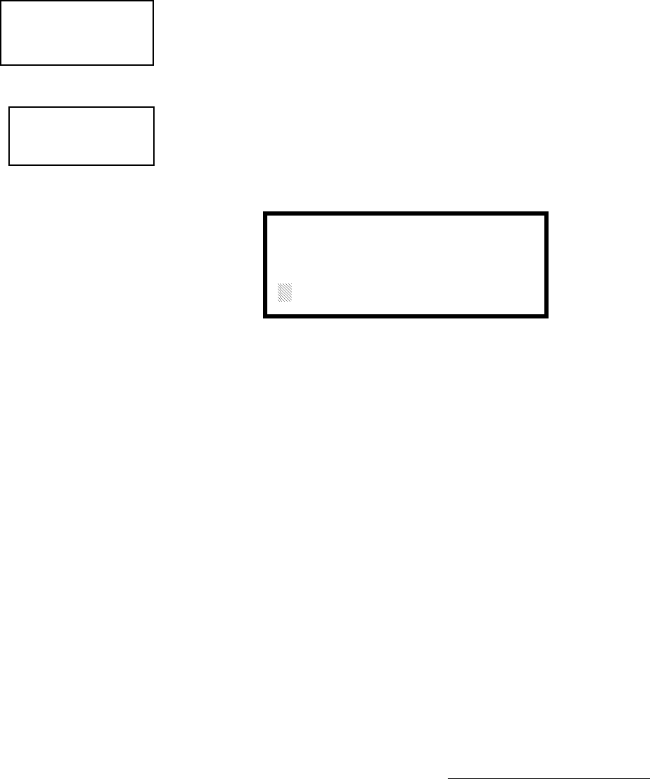
3URJUDPPLQJ 0DVWHU3URJUDPPLQJ/HYHO
8QLPRGH31&
3UHVVLQJRUZKLOHYLHZLQJWKH1RXQ$GMHFWLYH6FUHHQZLOOGLVSOD\VFUHHQVVLPLODU
WRWKHSUHYLRXV$GMHFWLYHDQG1RXQ6FUHHQV7KHQHZVFUHHQVZLOOOLVWFXVWRP
$GMHFWLYHVDQG1RXQVZKLFKKDYHEHHQSURJUDPPHGLQWRWKHFRQWUROSDQHOXVLQJWKH
3.SURJUDPPLQJNLW7KHVHGHVFULSWRUVDUHVHOHFWHGDVGHVFULEHGLQWKHSUHYLRXV
VHFWLRQV
'HVFULSWLRQ
7KH'HVFULSWLRQVHOHFWLRQDOORZVWKHSURJUDPPHUWRHQWHUDGGLWLRQDOLQIRUPDWLRQDERXW
WKHGHWHFWRUFXUUHQWO\EHLQJSURJUDPPHG7KLVLQIRUPDWLRQZLOOEHGLVSOD\HGDVSDUW
RIWKHGHYLFHODEHORQWKHGLVSOD\3UHVVLQJZKLOHYLHZLQJ(GLW'HWHFWRU6FUHHQ
ZLOOFDXVHWKHIROORZLQJVFUHHQWREHGLVSOD\HG
$IODVKLQJFXUVRUZLOODSSHDUDWWKHILUVWDVWHULVNWRWKHOHIW7KHSURJUDPPHUFDQHQWHU
DGGLWLRQDOGHVFULSWLYHLQIRUPDWLRQDERXWWKHGHYLFHEHLQJSURJUDPPHG7KLV
LQIRUPDWLRQZLOODSSHDURQWKHGLVSOD\DORQJZLWKWKHVWDQGDUGGHYLFHODEHO
LQIRUPDWLRQ
$PD[LPXPRIFKDUDFWHUVLQFOXGLQJVSDFHVFDQEHHQWHUHG7RHQWHU
DOSKDQXPHULFFKDUDFWHUVIURPWKHNH\SDGUHSHDWHGO\SUHVVWKHDSSURSULDWHNH\XQWLO
WKHGHVLUHGFKDUDFWHULVGLVSOD\HGLQWKHILUVWSRVLWLRQ)RUH[DPSOHWRHQWHUWKHOHWWHU
%SUHVVWKH$%&NH\WKUHHWLPHVWRWRJJOHWKURXJKWKHFKDUDFWHUV$DQG%3UHVV
WKHULJKWDUURZNH\WRPRYHWKHFXUVRURQHSRVLWLRQWRWKHULJKWDQGUHSHDWWKHSURFHVV
WRHQWHUWKHQH[WFKDUDFWHU7RHQWHUDVSDFHSUHVVWKH4=NH\IRXUWLPHVXQWLOD
EODQNDSSHDUVLQWKHGHVLUHGSRVLWLRQ:KHQDOOFKDUDFWHUVKDYHEHHQHQWHUHGSUHVVWKH
(QWHUNH\WRVWRUHWKHLQIRUPDWLRQ7KHGLVSOD\ZLOOUHWXUQWRWKH(GLW'HWHFWRU6FUHHQ
GLVSOD\LQJWKHQHZLQIRUPDWLRQDWWKHERWWRPRIWKHVFUHHQ
5HFDOO,QFUHPHQW)XQFWLRQ
,QDGGLWLRQWKHXVHUPD\XVHWKH5HFDOO,QFUHPHQWIXQFWLRQDWDQ\WLPHZKHQWKH
FXUVRULVRQWKHILUVWOHWWHURIWKH'HVFULSWLRQ$GMHFWLYHRU1RXQILHOGDVIROORZV
• If the zero key is pressed, a 0 is placed in the first letter position
• If the zero key is then pressed a second time with no intervening key actions, the
entire field is replaced with the field entered for the previous device programmed,
and the cursor moves to the last character of the field (Recall function). The
Recalled Adjective or Noun field may now be changed letter-by-letter
• If the zero key is pressed again with no other intervening key actions and the last
character in the field is a number 0-9, the number is incremented by one. If the last
character is a letter, it changes to a 0. If the last character goes from 9 to 0 and the
characters to the left of the last character are also numbers, they are also
incremented (overflow)
• The above increment function may be repeated with each press of the zero key
1=STANDARD ADJECTIVE
2=STANDARD NOUN
3=CUSTOM ADJECTIVE
4=CUSTOM NOUN
Noun/Adjective Screen
EDIT DETECTOR
1=NOUN/ADJECTIVE
2=DESCRIPTION
Edit Detector Screen #5
DESCRIPTION@@@@1D002
1=NOUN/ADJECTIVE
********************
Adjective/Noun Screen

0DVWHU3URJUDPPLQJ/HYHO 3URJUDPPLQJ
8QLPRGH31&
$VDQH[DPSOHWKHXVHUFRXOGTXLFNO\HQWHUµ)/5BB5220B¶DVIROORZV
1. The cursor is on the first letter of the Adjective field. Press the zero key twice to
display FLR_3
2. With the cursor on the first letter of the Noun field, press the zero key twice to recall
the display ROOM_304. The cursor automatically jumps from the first to the last
letter of the Noun field
3. With the cursor on the last letter of the Noun field, press the zero key again to
increment the room number to 305
4. Press the right arrow key to advance the zone field
5. Select a zone number from 00 to 99. Z00 (default zone) is the general alarm zone.
Z01 through Z99 may be selected to link software zones
3.6.1.2 Module Programming
3UHVVLQJZKLOHYLHZLQJ3RLQW3URJUDP6FUHHQZLOODOORZWKHSURJUDPPHUWRDGG
GHOHWHRUFKDQJHWKHSURJUDPPLQJRIDQDGGUHVVDEOHPRGXOH7KHIROORZLQJVFUHHQ
ZLOOEHGLVSOD\HGE\WKHFRQWUROSDQHO
3.6.1.2.1 Add Module
3UHVVLQJZKLOHYLHZLQJWKH0RGXOHV6FUHHQZLOOGLVSOD\WKHIROORZLQJVFUHHQZKLFK
DOORZVWKHSURJUDPPHUWRDGGDQHZPRGXOHDGGUHVVWRSURJUDPPLQJ
$IODVKLQJFXUVRUZLOODSSHDULQWKHSRVLWLRQRIWKHILUVWDVWHULVNWRWKHOHIW7KH
SURJUDPPHUNH\VLQWKHWKUHHGLJLWPRGXOHDGGUHVVVXFKDV
:KHQWKHODVWGLJLWLVNH\HGLQWKHIROORZLQJVFUHHQZLOOEHGLVSOD\HG
POINT PROGRAM
SELECT TYPE
1=DETECTOR
2=MODULE
Point Program Screen #2
@@@@@@MODULES
1=ADD
2=DELETE
3=EDIT
Modules Screen
@@@@@ADD@MODULE
ENTER@MODULE#
***
Add Module Screen #1
@@@@@ADD@MODULE
1=CONTROL
2=MONITOR
Add Module Screen #2

3URJUDPPLQJ 0DVWHU3URJUDPPLQJ/HYHO
8QLPRGH31&
3UHVVLQJIRU&RQWURO0RGXOHRUIRU0RQLWRU0RGXOHZLOOFDXVHWKHIROORZLQJ
VFUHHQWREHGLVSOD\HG
7KHSURJUDPPHUFDQFRQWLQXHDGGLQJPRGXOHVE\SUHVVLQJWKH(6&RUOHIWDUURZNH\
ZKLFKZLOOUHWXUQWKHGLVSOD\WRWKH$GG0RGXOH6FUHHQ
3.6.1.2.2 Delete Module
3UHVVLQJLQWKH0RGXOHV6FUHHQZLOOGLVSOD\WKH'HOHWH0RGXOH6FUHHQZKLFKDOORZV
WKHSURJUDPPHUWRGHOHWHDVSHFLILFPRGXOH
$IODVKLQJFXUVRUZLOODSSHDULQWKHSRVLWLRQRIWKHILUVWDVWHULVNWRWKHOHIW8VLQJWKH
SDQHONH\SDGNH\LQWKHPRGXOHDGGUHVVVXFKDV:KHQWKHODVWGLJLWLVNH\HGLQ
WKHIROORZLQJFRQILUPDWLRQWKDWWKHPRGXOHKDVEHHQGHOHWHGZLOOEHGLVSOD\HG
3.6.1.2.3 Edit Module Screen for Monitor Module
7KHSURJUDPPHUFDQFKDQJHDPRGXOHVH[LVWLQJRUIDFWRU\GHIDXOWSURJUDPPLQJE\
SUHVVLQJLQWKH0RGXOHV6FUHHQ7KHIROORZLQJVFUHHQZLOOEHGLVSOD\HG
@@@@@@ADD@MODULE
MODULE#@@@@@@@@@005
IS@ADDED
Add Module Screen #3
MODULES
1=ADD
2=DELETE
3=EDIT
Modules Screen
@@DELETE@MODULE
ENTER@MODULE#
***
Delete Module Screen
@@DELETE@MODULE
MODULE#@@@@@@@@@005
IS@DELETED
@@@@EDIT@MODULE
ENTER@MODULE@ADDRESS
***
Edit Module Screen

0DVWHU3URJUDPPLQJ/HYHO 3URJUDPPLQJ
8QLPRGH31&
$IODVKLQJFXUVRUZLOODSSHDULQWKHSRVLWLRQRIWKHILUVWDVWHULVNWRWKHOHIW7KH
SURJUDPPHUNH\VLQWKHWKUHHGLJLWPRGXOHDGGUHVVVXFKDV:KHQWKHODVWGLJLWLV
NH\HGLQLIWKHVHOHFWHGDGGUHVVKDVQRWEHHQDGGHGWRSURJUDPPLQJDVFUHHQVKRZLQJ
LQIRUPDWLRQDERXWWKHKLJKHVWDGGUHVVWKDWLVLQVWDOOHGZLOOEHGLVSOD\HG,IQRPRGXOHV
DUHLQVWDOOHGRQWKHORRSWKHIROORZLQJVFUHHQZLOOEHGLVSOD\HG
,IWKHVHOHFWHGDGGUHVVKDVEHHQDGGHGWRSURJUDPPLQJEXWDPRGXOHVXFKDVD
PRQLWRUPRGXOHZLWKWKHVHOHFWHGDGGUHVVLVQRWSK\VLFDOO\LQVWDOOHGRQWKH6/&RUKDV
DFRPPXQLFDWLRQIDXOWWKHIROORZLQJVFUHHQZLOOEHGLVSOD\HG
,IWKHVHOHFWHGDGGUHVVKDVEHHQDGGHGWRSURJUDPPLQJDQGDPRGXOHVXFKDVD
PRQLWRUPRGXOHZLWKWKHVHOHFWHGDGGUHVVLVSK\VLFDOO\LQVWDOOHGRQWKH6/&DQGLV
FRPPXQLFDWLQJZLWKWKHFRQWUROSDQHOWKHIROORZLQJVFUHHQZLOOEHGLVSOD\HG
7RFKDQJHWKHSURJUDPPLQJIRUWKHGLVSOD\HGPRGXOHSUHVVWKHNH\ERDUGGRZQDUURZ
NH\WRYLHZWKHIROORZLQJ(GLW0RQLWRUVFUHHQV,QWKHSUHFHGLQJH[DPSOH
✓Normal - indicates that the module with the selected address is physically
installed on the SLC and communicating with the control panel (enabled)
✓<ADJ><NOUN> - represents the adjective and noun, which have been
programmed, describing the location of the displayed device
✓ZNNN - represents the first of five possible software zones that the module is
assigned to (NNN = the two digit zone number from 000 - 099)
✓1M012 - represents the Loop, Device type and Device address (1 = SLC Loop 1,
M=Module and 012 = Module Address 012)
,IWKHVHOHFWHGDGGUHVVFRUUHVSRQGVWRDFRQWUROPRGXOHDVFUHHQGLVSOD\LQJ
LQIRUPDWLRQDERXWWKHFRQWUROPRGXOHZLWKWKHVHOHFWHGDGGUHVVZLOOEHGLVSOD\HGDV
VKRZQLQ(GLW0RGXOH6FUHHQIRU&RQWURO0RGXOHVRQSDJH
@@@@@NO@MODULE
@@@@@INSTALLED
Edit Module Screen
@TROUBL@MONITOR
@@@@@@<ADJ><NOUN>
@@@@@@@@@@@@@@@@ZNNN
@@@@@@@@@@@@@@@1M012
@NORMAL@MONITOR
@@@@@@@<ADJ><NOUN>
@@@@@@@@@@@@@@@@@ZNNN
@@@@@@@@@@@@@@@@1M012
See Page

3URJUDPPLQJ 0DVWHU3URJUDPPLQJ/HYHO
8QLPRGH31&
,IWKHVHOHFWHGDGGUHVVFRUUHVSRQGVWRDPRQLWRUPRGXOHDVFUHHQGLVSOD\LQJ
LQIRUPDWLRQDERXWWKHPRGXOHZLWKWKHVHOHFWHGDGGUHVVZLOOEHGLVSOD\HGDVLOOXVWUDWHG
LQWKHIROORZLQJ
@NORMAL@MONITOR
@@@@@@<ADJ><NOUN>
@@@@@@@@@@@@@@@@@ZNNN
@@@@@@@@@@@@@@@@1M012
EDIT@MONITOR@@1M012
1=ENABLED@@@@@@@@YES
2=TYPE@@MONITOR
Edit Monitor Screen #2
EDIT@MONITOR@@1M012
1=PRE-SIGNAL@@@@@@NO
2=PAS@@@@@@@@@@@@@NO
Edit Monitor Screen #3
EDIT@MONITOR@@1M012
1=WALKTEST@@@@@@@YES
2=ZONE@ASSIGNMENT
00@**@**@**@**
Edit Monitor Screen #4
EDIT@MONITOR@@1M012
1=ADJECTIVE/NOUN
2=DESCRIPTION
********************
Edit Monitor Screen #5

0DVWHU3URJUDPPLQJ/HYHO 3URJUDPPLQJ
8QLPRGH31&
(QDEOH'LVDEOH0RGXOH
7R(QDEOHRU'LVDEOHWKHPRQLWRUPRGXOHSUHVVWKHNH\ZKLOHYLHZLQJWKH(GLW
0RGXOH6FUHHQ(DFKSUHVVRIWKHNH\ZLOOWRJJOHWKHVFUHHQEHWZHHQ(QDEOHG<HV
DQG(QDEOHG1R,I(QDEOHG1RLVVHOHFWHGWKHPRGXOHZLOOQRWEHSROOHGE\WKH
FRQWUROSDQHOSUHYHQWLQJWKHPRGXOHIURPUHSRUWLQJDODUPVDQGWURXEOHVWRWKHSDQHO
7KHFRQWUROSDQHOZLOOLQGLFDWHDV\VWHPWURXEOHFRQGLWLRQDQGWKH'LVDEOH/('ZLWK
WXUQRQLIDQ\GHYLFHVDUHGLVDEOHG
7\SH0RQLWRU
8VLQJWKH3.8SORDG'RZQORDGXWLOLW\SURJUDPXQLTXHXVHUGHILQHGPRQLWRU
W\SHVFDQEHFUHDWHGDQGORDGHGLQWRWKH)$&3IRUODWHUXVH7KH)$&3UHVSRQVHWRWKH
DFWLYDWLRQRIDXVHUGHILQHGW\SHLVWKHVDPHDVPRVWSUHYLRXVVWDQGDUGW\SHVLQWKHOLVW
WKXVDOORZLQJDYDULHW\RIXVHUGHILQHGW\SHVDQGUHVSRQVHV7RVHOHFWWKHW\SHRI
PRQLWRUPRGXOHEHLQJSURJUDPPHGSUHVVWKHNH\ZKLOHYLHZLQJWKH(GLW0RQLWRU
6FUHHQ7KLVZLOOFDXVHWKHFRQWUROSDQHOWRGLVSOD\WKHIROORZLQJ0RQLWRU7\SH
6FUHHQV
EDIT MONITOR
1=ENABLED
2=TYPE MONITOR
Edit Monitor Screen #2
@@@MONITOR@TYPE
1=PULL-STATION
2=USER-DEFINED-1
3=WATERFLOW
Monitor Type Screen #1
@@@MONITOR@TYPE
1=USER-DEFINED-3
2=FUTURE USE
3=USER-DEFINED-4
Monitor Type Screen #3
Monitor Type Screen #4
@@@MONITOR@TYPE
1=USER-DEFINED-6
2=MEDIC-ALERT
3=USER-DEFINED-7
Monitor Type Screen #6
@@@MONITOR@TYPE
1=SMOKE-CONVENTIONAL
2=HEAT-DETECTOR
3=USER-DEFINED-5
Monitor Type Screen #5
@@@MONITOR@TYPE
1=HAZARD-ALERT
2=USER-DEFINED-8
3=TORNADO-ALERT
Monitor Type Screen #7
@@@MONITOR@TYPE
1=TAMPER
2=SUPERVISORY
3=SUPERVISORY-AR
@@@MONITOR@TYPE
1=USER-DEFINED-9
2=USER-DEFINED-10
3=USER-DEFINED-11
Monitor Type Screen #8
@@@MONITOR@TYPE
1=USER-DEFINED-2
2=MONITOR
3=BLANK
Monitor Type Screen #2
Note: For the SUPERVISORY-AR selection, AR refers to AutoResettable

3URJUDPPLQJ 0DVWHU3URJUDPPLQJ/HYHO
8QLPRGH31&
:KLOHYLHZLQJRQHRIWKH0RQLWRU7\SHVFUHHQVVHOHFWWKHW\SHRIPRQLWRUPRGXOH
EHLQJSURJUDPPHGE\SUHVVLQJWKHFRUUHVSRQGLQJNH\SDGQXPEHUNH\7KHGLVSOD\
ZLOOUHWXUQWRWKH(GLW0RQLWRU6FUHHQZKLFKZLOOVKRZWKHQHZW\SHVHOHFWLRQ
0RQLWRUPRGXOHW\SHVHOHFWLRQZLOODIIHFWWKHIXQFWLRQRIWKHSRLQWDVIROORZV
@@@@MONITOR@TYPE
1=DRILL-SWITCH
2=PAS-BYPASS
3=USER-DEFINED-14
Monitor Type Screen #12
Monitor Type Screen #11
@@@@MONITOR@TYPE
1=ACK-SWITCH
2=SIL-SWITCH
3=RESET-SWITCH
Monitor Type Screen #9
@@@@MONITOR@TYPE
1=POWER-MONITOR
2=TROUBLE-MONITOR
3=USER-DEFINED-12
Monitor Type Screen #10
@@@@MONITOR@TYPE
1=PROC-MON
2=PROCMON-AR
3=USER-DEFINED-13
Note: For the PROCMON-AR selection, PROCMON refers to Process Monitor and AR refers to AutoResettable
Monitor Type Action When Activated
Pull-Station Fire Alarm
User-Defined-1 Fire Alarm
Waterflow Fire Alarm Delayed
User-Defined-2 Fire Alarm Delayed
Monitor Fire Alarm
Blank Fire Alarm
User-Defined-3 Fire Alarm
Future Use Future Use
User-Defined-4 Supervisory on partial short, Fire Alarm on full short
Smoke-Conventional Fire Alarm
Heat-Detector Fire Alarm
User-Defined-5 Fire Alarm
User-Defined-6 Fire Alarm
Medic-Alert Supervisory, latching
User-Defined-7 Supervisory, latching
Hazard-Alert Supervisory, latching
User-Defined-8 Supervisory, latching
Tornado-Alert Supervisory, latching
User-Defined-9 Supervisory, latching
User-Defined-10 Supervisory, latching
User-Defined-11 Supervisory, latching
Tamper Supervisory, nonlatching (tracking)
Supervisory Supervisory, latching
Supervisory-AR Supervisory, nonlatching (tracking)
Power-Monitor AC Fault
Trouble-Monitor Trouble
User-Defined-12 Trouble
Proc-Mon Piezo
Procmon-Auto Piezo, nonlatching (tracking)
User-Defined-13 Piezo, nonlatching (tracking)
Ack-Switch Acts like panel Acknowledge Key
Sil-Switch Acts like panel Alarm Silence Key
Reset-Switch Acts like panel Reset Key
Drill-Switch Acts like panel Drill Key
PAS-Bypass PAS Disable
User-Defined-14 PAS Disable
0DVWHU3URJUDPPLQJ/HYHO 3URJUDPPLQJ
8QLPRGH31&
3UHVLJQDO
To enable the Pre-signal feature, press 1 while viewing Edit Monitor Screen #3 until
the display reads Pre-signal Yes. Each press of the 1 key will cause the display to
toggle between Pre-signal Yes and Pre-signal No. Refer to "Presignal" on page 113 for
additional information.
3$6
7RHQDEOHWKH3$6IHDWXUHSUHVVZKLOHYLHZLQJWKH(GLW'HWHFWRU6FUHHQXQWLOWKH
GLVSOD\UHDGV3$6<HV(DFKSUHVVRIWKHNH\ZLOOFDXVHWKHGLVSOD\WRWRJJOHEHWZHHQ
3$6<HVDQG3$61R5HIHUWR3RVLWLYH$ODUP6HTXHQFHRQSDJHIRUDGGLWLRQDO
LQIRUPDWLRQ
:DONWHVW
7KH:DONWHVWIHDWXUHDOORZVRQHSHUVRQWRWHVWWKHV\VWHPGHYLFHVZLWKRXWWKHQHFHVVLW\
RIPDQXDOO\UHVHWWLQJWKHFRQWUROSDQHODIWHUHDFKGHYLFHDFWLYDWLRQ7RHQDEOHGHYLFHV
ZKLFKDUHFRQQHFWHGWRDPRQLWRUPRGXOHIRUWKH:DONWHVWIHDWXUHSUHVVZKLOH
YLHZLQJWKH(GLW0RQLWRU6FUHHQXQWLOWKHGLVSOD\UHDGV:DONWHVW<HV(DFKSUHVVRI
WKHNH\ZLOOFDXVHWKHGLVSOD\WRWRJJOHEHWZHHQ:DONWHVW<HVDQG:D ONWHV W1 R5HIHU
WR:DONWHVWRQSDJHIRUDGGLWLRQDOLQIRUPDWLRQ
=RQH$VVLJQPHQW
$PD[LPXPRIILYH]RQHVFDQEHSURJUDPPHGWRHDFKDGGUHVVDEOHPRQLWRUPRGXOH
3UHVVLQJZKLOHYLHZLQJ(GLW0RQLWRU6FUHHQGLVSOD\VWKHIROORZLQJVFUHHQ
1RWHWKDW=UHSUHVHQWVWKH=RQH1XPEHUVFRUUHVSRQGLQJWRWKLVGHYLFH7KH
IDFWRU\GHIDXOWIRUDQXQSURJUDPPHGGHYLFHLV=IRUJHQHUDODODUP]RQH$IODVKLQJ
FXUVRUZLOODSSHDURQWKHILUVWWRWKHOHIW(QWHUWKHWZRGLJLWQXPEHUFRUUHVSRQGLQJ
WRWKH]RQHWKDWLVWREHDVVLJQHGWRWKLVGHYLFH7KHFXUVRUPRYHVWRWKHQH[W=
GHVLJQDWLRQ&RQWLQXHHQWHULQJ]RQHDVVLJQPHQWVRUWKHUHPDLQLQJ]RQHVFDQEHOHIW
EODQNRUSURJUDPPHGDVJHQHUDODODUP]RQHV=:KHQDOOGHVLUHGFKDQJHVKDYH
EHHQPDGHSUHVVWKH(QWHUNH\WRVWRUHWKH]RQHDVVLJQPHQWV7KHGLVSOD\ZLOOUHWXUQ
WRWKH(GLW0RQLWRU6FUHHQ
1RXQ$GMHFWLYH
7KH1RXQ$GMHFWLYHVHOHFWLRQDOORZVWKHSURJUDPPHUWRHQWHUVSHFLILFGHVFULSWRUV
DERXWWKHPRQLWRUPRGXOHFXUUHQWO\EHLQJSURJUDPPHG3UHVVLQJZKLOHYLHZLQJ(GLW
0RQLWRU6FUHHQZLOOFDXVHWKHIROORZLQJVFUHHQWREHGLVSOD\HG
EDIT MONITOR
1=PRE-SIGNAL
2=PAS
Edit Monitor Screen #3
See Page
See Page
EDIT MONITOR
1=WALKTEST
2=ZONE ASSIGNMENT
00 ** ** ** **
Edit Monitor Screen #4
@@MON@ZONE@ASSIGN
Z00@Z**@Z**@Z**@Z**
Zone Assignment Screen
EDIT MONITOR
1=NOUN/ADJECTIVE
2=DESCRIPTION
*****************
Edit Monitor Screen #5
1=STANDARD@ADJECTIVE
2=STANDARD@NOUN
3=CUSTOM@ADJECTIVE
4=CUSTOM@NOUN
Noun/Adjective Screen

3URJUDPPLQJ 0DVWHU3URJUDPPLQJ/HYHO
8QLPRGH31&
Pressing 1 while viewing the Noun/Adjective Screen will cause the following
screen(s) to be displayed. Note that the keyboard down arrow key must be pressed to
see all the Adjective screens. Press the number corresponding to the adjective that is
to be used as a descriptor for the location of the monitor module currently being
programmed.
1=STANDARD ADJECTIVE
2=STANDARD NOUN
3=CUSTOM ADJECTIVE
4=CUSTOM NOUN
Noun/Adjective Screen
**********************
1=NORTH
2=SOUTH
3=EAST
Adjective Screen #1
**********************
1=WEST
2=FRONT
3=CENTER
Adjective Screen #2
**********************
1=REAR
2=UPPER
3=LOWER
Adjective Screen #3
**********************
1=MAIN
2=FIRST
3=2ND
Adjective Screen #4
**********************
1=3RD
2=4TH
3=5TH
Adjective Screen #5
**********************
1=FLOOR 4
2=FLOOR 5
3=ROOM
Adjective Screen #7
**********************
1=FLOOR 1
2=FLOOR 2
3=FLOOR 3
Adjective Screen #6

0DVWHU3URJUDPPLQJ/HYHO 3URJUDPPLQJ
8QLPRGH31&
3UHVVLQJZKLOHYLHZLQJWKH1RXQ$GMHFWLYH6FUHHQZLOOFDXVHWKHIROORZLQJ
VFUHHQVWREHGLVSOD\HG1RWHWKDWWKHNH\ERDUGGRZQDUURZNH\PXVWEHSUHVVHGWR
VHHDOOWKH1RXQVFUHHQVPress the number corresponding to the noun that is to be used
as a descriptor for the location of the monitor module currently being programmed.
3UHVVLQJRUZKLOHYLHZLQJWKH1RXQ$GMHFWLYH6FUHHQZLOOGLVSOD\VFUHHQVVLPLODU
WRWKHSUHYLRXV$GMHFWLYHDQG1RXQ6FUHHQV7KHQHZVFUHHQVZLOOOLVW&XVWRP
$GMHFWLYHVDQG1RXQVZKLFKKDYHEHHQSURJUDPPHGLQWRWKHFRQWUROSDQHOXVLQJWKH
3.SURJUDPPLQJNLW
1=STANDARD ADJECTIVE
2=STANDARD NOUN
3=CUSTOM ADJECTIVE
4=CUSTOM NOUN
Noun/Adjective Screen
**********************
1=BASEMENT
2=BOILER@RM
3=CLASSROOM
Noun Screen #1
**********************
1=CLOSET
2=CORRIDOR
3=ELECTRIC@RM
Noun Screen #2
**********************
1=ELEVATOR
2=ENTRANCE
3=FLOOR
Noun Screen #3
**********************
1=GARAGE
2=HALLWAY
3=HVAC@RM
Noun Screen #4
**********************
1=KITCHEN
2=LOBBY
3=OFFICE
Noun Screen #5
**********************
1=STAIRWAY
2=STOREROOM
3=WING
Noun Screen #7
**********************
1=PATIENT
2=RESTROOM
3=ROOM
Noun Screen #6

3URJUDPPLQJ 0DVWHU3URJUDPPLQJ/HYHO
8QLPRGH31&
'HVFULSWLRQ
7KH'HVFULSWLRQVHOHFWLRQDOORZVWKHSURJUDPPHUWRHQWHUDGGLWLRQDOLQIRUPDWLRQDERXW
WKHPRQLWRUPRGXOHFXUUHQWO\EHLQJSURJUDPPHG7KLVLQIRUPDWLRQZLOOEHGLVSOD\HG
DVSDUWRIWKHGHYLFHODEHORQWKH/&'GLVSOD\3UHVVLQJZKLOHYLHZLQJ(GLW0RQLWRU
6FUHHQZLOOFDXVHWKHIROORZLQJVFUHHQWREHGLVSOD\HG
$IODVKLQJFXUVRUZLOODSSHDUDWWKHILUVWDVWHULVNWRWKHOHIW7KHSURJUDPPHUFDQHQWHU
DGGLWLRQDOGHVFULSWLYHLQIRUPDWLRQDERXWWKHGHYLFHEHLQJSURJUDPPHG7KLV
LQIRUPDWLRQZLOODSSHDURQWKH/&'GLVSOD\DORQJZLWKWKHVWDQGDUGGHYLFHODEHO
LQIRUPDWLRQ
$PD[LPXPRIFKDUDFWHUVLQFOXGLQJVSDFHVFDQEHHQWHUHG7RHQWHU
DOSKDQXPHULFFKDUDFWHUVIURPWKHNH\SDGUHSHDWHGO\SUHVVWKHDSSURSULDWHNH\XQWLO
WKHGHVLUHGFKDUDFWHULVGLVSOD\HGLQWKHILUVWSRVLWLRQ)RUH[DPSOHWRHQWHUWKHOHWWHU
%SUHVVWKH$%&NH\WKUHHWLPHVWRWRJJOHWKURXJKWKHFKDUDFWHUV$DQG%3UHVV
WKHULJKWDUURZNH\WRPRYHWKHFXUVRURQHSRVLWLRQWRWKHULJKWDQGUHSHDWWKHSURFHVV
WRHQWHUWKHQH[WFKDUDFWHU7RHQWHUDVSDFHSUHVVWKH4=NH\IRXUWLPHVXQWLOD
EODQNDSSHDUVLQWKHGHVLUHGSRVLWLRQ:KHQDOOFKDUDFWHUVKDYHEHHQHQWHUHGSUHVVWKH
(QWHUNH\WRVWRUHWKHLQIRUPDWLRQ7KHGLVSOD\ZLOOUHWXUQWRWKH(GLW0RQLWRU6FUHHQ
GLVSOD\LQJWKHQHZLQIRUPDWLRQDWWKHERWWRPRIWKHVFUHHQ
5HFDOO,QFUHPHQW)XQFWLRQ
,QDGGLWLRQWKHXVHUPD\XVHWKH5HFDOO,QFUHPHQWIXQFWLRQDWDQ\WLPHZKHQWKH
FXUVRULVRQWKHILUVWOHWWHURIWKH$GMHFWLYHRU1RXQILHOGDVIROORZV
• If the zero key is pressed, a 0 is placed in the first letter position
• If the zero key is then pressed a second time with no intervening key actions, the
entire Adjective field is replaced with the field entered for the previous device
programmed, and the cursor moves to the last character of the field (Recall
function). The Recalled Adjective or Noun field may now be changed letter-by-
letter
• If the zero key is pressed again with no other intervening key actions and the last
character in the field is a number 0-9, the number is incremented by one. If the last
character is a letter, it changes to a 0. If the last character goes from 9 to 0 and the
characters to the left of the last character are also numbers, they are also
incremented (overflow)
• The above increment function may be repeated with each press of the zero key
EDIT MONITOR
1=NOUN/ADJECTIVE
2=DESCRIPTION
*****************
Edit Monitor Screen #4
DESCRIPTION@@@@1M012
1=NOUN/ADJECTIVE
********************
Noun/Adjective Screen

0DVWHU3URJUDPPLQJ/HYHO 3URJUDPPLQJ
8QLPRGH31&
$VDQH[DPSOHWKHXVHUFRXOGTXLFNO\HQWHUµ)/5BB5220¶DVIROORZV
1. The cursor is on the first letter of the Adjective field. Press the zero key twice to
display FLR_3
2. With the cursor on the first letter of the Noun field, press the zero key twice to recall
the display ROOM_304. The cursor automatically jumps from the first to the last
letter of the Noun field
3. With the cursor on the last letter of the Noun field, press the zero key again to
increment the room number to 305
4. Press the right arrow key to advance the zone field
5. Select a zone number from 00 to 99. Z00 (default zone) is the general alarm zone.
Z01 through Z99 may be selected to link software zones
3.6.1.2.4 Edit Module Screen for Control Modules
7KHSURJUDPPHUFDQFKDQJHDPRGXOH¶VH[LVWLQJRUIDFWRU\GHIDXOWSURJUDPPLQJE\
SUHVVLQJLQWKH0RGXOHV6FUHHQ7KHIROORZLQJVFUHHQZLOOEHGLVSOD\HG
$IODVKLQJFXUVRUZLOODSSHDULQWKHSRVLWLRQRIWKHILUVWDVWHULVNWRWKHOHIW
7KHSURJUDPPHUNH\VLQWKHWKUHHGLJLWPRGXOHDGGUHVVVXFKDV:KHQWKHODVW
GLJLWLVNH\HGLQLIWKHVHOHFWHGDGGUHVVFRUUHVSRQGVWRDFRQWUROPRGXOHDVFUHHQ
GLVSOD\LQJLQIRUPDWLRQDERXWWKHFRQWUROPRGXOHZLWKWKHVHOHFWHGDGGUHVVZLOOEH
GLVSOD\HGDVLOOXVWUDWHGLQWKHIROORZLQJ
,QWKHSUHFHGLQJH[DPSOH
✓Normal - indicates that the module with the selected address is physically
installed on the SLC and communicating with the control panel (enabled)
✓<ADJ><NOUN> - represents the adjective and noun, which have been
programmed, describing the location of the displayed device
✓Control - indicates that the selected module is a control module
✓S or * - represents Silenceable (S) or Nonsilenceable (*)
✓W or * - represents Waterflow Timer Delay (W = Waterflow Timer Delay
enabled, * = Waterflow Timer Delay disabled)
✓ZNNN - represents the first of five possible software zones that the module is
assigned to (NNN = the three digit zone number from 000 - 099)
✓1M002 - represents the Loop, Device type and Device address (1 = SLC Loop 1,
M=Module and 002 = Module Address 02)
MODULES
1=ADD
2=DELETE
3=EDIT
Modules Screen
@@@@EDIT@MODULE
ENTER@MODULE@ADDRESS
***
Edit Module Screen
NORMAL@@@@@@CONTROL
@@@@@@<ADJ><NOUN>
@@@@@@@@@@SW@@ZNNN
@@@@@@@@@@@@@@1M002
Edit Control Screen #1

3URJUDPPLQJ 0DVWHU3URJUDPPLQJ/HYHO
8QLPRGH31&
7RFKDQJHWKHSURJUDPPLQJIRUWKHGLVSOD\HGPRGXOHSUHVVWKHNH\ERDUGGRZQDUURZ
NH\WRYLHZWKHIROORZLQJ(GLW&RQWUROVFUHHQV
(QDEOH'LVDEOH0RGXOH
7R(QDEOHRU'LVDEOHWKHFRQWUROPRGXOHSUHVVWKHNH\ZKLOHYLHZLQJWKH(GLW
&RQWURO6FUHHQ(DFKSUHVVRIWKHNH\ZLOOWRJJOHWKHVFUHHQEHWZHHQ(QDEOHG<HV
DQG(QDEOHG1R,I(QDEOHG1RLVVHOHFWHGWKHPRGXOHZLOOQRWEHSROOHGE\WKH
FRQWUROSDQHOSUHYHQWLQJWKHPRGXOHIURPDFWLYDWLQJLWVRXWSXWGHYLFHV7KHFRQWURO
SDQHOZLOOLQGLFDWHDV\VWHPWURXEOHFRQGLWLRQDQGWKH'LVDEOH/('ZLOOWXUQRQLIDQ\
GHYLFHVDUHGLVDEOHG
EDIT@CONTROL
1=ENABLED@@@@@@@@YES
2=TYPE@@CONTROL
3=SILENCEABLE@@@@YES
Edit Control Screen #2
EDIT@CONTROL
1=WALKTEST@@@@@@@YES
2=ZONE@ASSIGNMENT
00@**@**@**@**
Edit Control Screen #3
EDIT@CONTROL
1=NOUN/ADJECTIVE
2=DESCRIPTION
********************
Edit Control Screen #4
EDIT CONTROL
1=ENABLED
2=TYPE
3=SILENCEABLE
Edit Control Screen #2

0DVWHU3URJUDPPLQJ/HYHO 3URJUDPPLQJ
8QLPRGH31&
7\SH
7RVHOHFWWKHW\SHRIFRQWUROPRGXOHEHLQJSURJUDPPHGSUHVVWKHNH\ZKLOHYLHZLQJ
WKH(GLW&RQWURO6FUHHQ7KLVZLOOFDXVHWKHFRQWUROSDQHOWRGLVSOD\WKHIROORZLQJ
&RQWURO7\SH6FUHHQV
:KLOHYLHZLQJRQHRIWKH&RQWURO7\SHVFUHHQVVHOHFWWKHW\SHRIFRQWUROPRGXOH
EHLQJSURJUDPPHGE\SUHVVLQJWKHFRUUHVSRQGLQJNH\SDGQXPEHUNH\7KHGLVSOD\
ZLOOUHWXUQWRWKH(GLW&RQWURO6FUHHQDQGLQGLFDWHWKHQHZW\SHVHOHFWLRQ
7KHIROORZLQJWDEOHFRQWDLQVFRQWUROPRGXOHW\SHFRGHVDQGWKHLUIXQFWLRQV
6LOHQFHDEOH
7KH6LOHQFHDEOHVHOHFWLRQDOORZVWKHSURJUDPPHUWRVHOHFWZKHWKHURXWSXWGHYLFHV
FRQQHFWHGWRWKHFRQWUROPRGXOHFDQEHVLOHQFHGHLWKHUE\SUHVVLQJWKH$ODUP6LOHQFH
NH\RUE\HQDEOLQJ$XWRVLOHQFH3UHVVLQJWKHNH\ZKLOHYLHZLQJ(GLW&RQWURO6FUHHQ
ZLOOHQDEOHWKH6LOHQFHDEOHIHDWXUHFDXVLQJWKHGLVSOD\WRUHDG6LOHQFHDEOH<HV
5HSHDWHGSUHVVHVRIWKHNH\ZLOOFDXVHWKHGLVSOD\WRWRJJOHEHWZHHQ6LOHQFHDEOH<HV
DQG6LOHQFHDEOH1R
Control Type Special Function
Blank None
Bell Circuit None
Horn Circuit None
Sounders None
Relay Ignore Open Circuit
Strobe Circuit None
Control None
@@@CONTROL@TYPE
1=BLANK
2=BELL-CIRCUIT
3=HORN-CIRCUIT
Control Type Screen #1
@@@CONTROL@TYPE
1=CONTROL
Control Type Screen #3
@@@CONTROL@TYPE
1=SOUNDERS
2=RELAY-1FC
3=STROBE-CKT
Control Type Screen #2
3URJUDPPLQJ 0DVWHU3URJUDPPLQJ/HYHO
8QLPRGH31&
:DONWHVW
7KH:DONWHVWIHDWXUHDOORZVRQHSHUVRQWRWHVWWKHV\VWHPGHYLFHVZLWKRXWWKHQHFHVVLW\
RIPDQXDOO\UHVHWWLQJWKHFRQWUROSDQHODIWHUHDFKGHYLFHDFWLYDWLRQ7RHQDEOHGHYLFHV
ZKLFKDUHFRQQHFWHGWRDFRQWUROPRGXOHIRUWKH:DONWHVWIHDWXUHSUHVVZKLOH
YLHZLQJWKH(GLW&RQWURO6FUHHQXQWLOWKHGLVSOD\UHDGV:DONWHVW<HV(DFKSUHVVRI
WKHNH\ZLOOFDXVHWKHGLVSOD\WRWRJJOHEHWZHHQ:DONWHVW<HVDQG:D ONWHV W1 R5HIHU
WR:DONWHVWRQSDJHIRUDGGLWLRQDOLQIRUPDWLRQ
=RQH$VVLJQPHQW
$PD[LPXPRIILYH]RQHVFDQEHSURJUDPPHGWRHDFKDGGUHVVDEOHFRQWUROPRGXOH
3UHVVLQJZKLOHYLHZLQJ(GLW&RQWURO6FUHHQGLVSOD\VWKHIROORZLQJVFUHHQ
1RWHWKDW=UHSUHVHQWVWKH=RQH1XPEHUVFRUUHVSRQGLQJWRWKLVGHYLFH7KH
IDFWRU\GHIDXOWIRUDQXQSURJUDPPHGGHYLFHLV=IRUJHQHUDODODUP]RQH$IODVKLQJ
FXUVRUZLOODSSHDURQWKHILUVWWRWKHOHIW(QWHUWKHWZRGLJLWQXPEHUFRUUHVSRQGLQJ
WRWKH]RQHWKDWLVWREHDVVLJQHGWRWKLVGHYLFH7KHFXUVRUPRYHVWRWKHQH[W=
GHVLJQDWLRQ&RQWLQXHHQWHULQJ]RQHDVVLJQPHQWVRUWKHUHPDLQLQJ]RQHVFDQEHOHIW
EODQNRUSURJUDPPHGDVJHQHUDODODUP]RQHV=:KHQDOOGHVLUHGFKDQJHVKDYH
EHHQPDGHSUHVVWKH(QWHUNH\WRVWRUHWKH]RQHDVVLJQPHQWV7KHGLVSOD\ZLOOUHWXUQ
WRWKH(GLW&RQWURO6FUHHQ
1RXQ$GMHFWLYH
7KH1RXQ$GMHFWLYHVHOHFWLRQDOORZVWKHSURJUDPPHUWRHQWHUVSHFLILFGHVFULSWRUV
DERXWWKHFRQWUROPRGXOHFXUUHQWO\EHLQJSURJUDPPHG3UHVVLQJZKLOHYLHZLQJ(GLW
&RQWURO6FUHHQZLOOFDXVHWKHIROORZLQJVFUHHQWREHGLVSOD\HG
EDIT CONTROL
1=WALKTEST
2=ZONE ASSIGNMENT
00 ** ** ** **
Edit Control Screen #3
@@ZONE@ASSIGNMENT
Z00@Z**@Z**@Z**@Z**
Zone Assignment Screen
EDIT CONTROL
1=NOUN/ADJECTIVE
2=DESCRIPTION
Edit Control Screen #4
1=STANDARD@ADJECTIVE
2=STANDARD@NOUN
3=CUSTOM@ADJECTIVE
4=CUSTOM@NOUN
Noun/Adjective Screen

0DVWHU3URJUDPPLQJ/HYHO 3URJUDPPLQJ
8QLPRGH31&
3UHVVLQJZKLOHYLHZLQJWKH1RXQ$GMHFWLYH6FUHHQZLOOFDXVHWKHIROORZLQJ
VFUHHQVWREHGLVSOD\HG1RWHWKDWWKHNH\ERDUGGRZQDUURZNH\PXVWEHSUHVVHGWR
VHHDOOWKH$GMHFWLYHVFUHHQVPress the number corresponding to the adjective that is
to be used as a descriptor for the location of the control module currently being
programmed.
1=STANDARD ADJECTIVE
2=STANDARD NOUN
3=CUSTOM ADJECTIVE
4=CUSTOM NOUN
Noun/Adjective Screen
**********************
1=NORTH
2=SOUTH
3=EAST
Adjective Screen #1
**********************
1=WEST
2=FRONT
3=CENTER
Adjective Screen #2
**********************
1=REAR
2=UPPER
3=LOWER
Adjective Screen #3
**********************
1=MAIN
2=FIRST
3=2ND
Adjective Screen #4
**********************
1=3RD
2=4TH
3=5TH
Adjective Screen #5
**********************
1=FLOOR 4
2=FLOOR 5
3=ROOM
Adjective Screen #7
**********************
1=FLOOR 1
2=FLOOR 2
3=FLOOR 3
Adjective Screen #6

3URJUDPPLQJ 0DVWHU3URJUDPPLQJ/HYHO
8QLPRGH31&
3UHVVLQJZKLOHYLHZLQJWKH1RXQ$GMHFWLYH6FUHHQZLOOFDXVHWKHIROORZLQJ
VFUHHQVWREHGLVSOD\HG1RWHWKDWWKHNH\ERDUGGRZQDUURZNH\PXVWEHSUHVVHGWR
VHHDOOWKH1RXQVFUHHQVPress the number corresponding to the noun that is to be used
as a descriptor for the location of the control module currently being programmed.
3UHVVLQJRUZKLOHYLHZLQJWKH1RXQ$GMHFWLYH6FUHHQZLOOGLVSOD\VFUHHQVVLPLODU
WRWKHSUHYLRXV$GMHFWLYHDQG1RXQ6FUHHQV7KHQHZVFUHHQVZLOOOLVW&XVWRP
$GMHFWLYHVDQG1RXQVZKLFKKDYHEHHQSURJUDPPHGLQWRWKHFRQWUROSDQHOXVLQJWKH
3.SURJUDPPLQJNLW
1=STANDARD ADJECTIVE
2=STANDARD NOUN
3=CUSTOM ADJECTIVE
4=CUSTOM NOUN
Noun/Adjective Screen
**********************
1=BASEMENT
2=BOILER@RM
3=CLASSROOM
Noun Screen #1
**********************
1=CLOSET
2=CORRIDOR
3=ELECTRIC@RM
Noun Screen #2
**********************
1=ELEVATOR
2=ENTRANCE
3=FLOOR
Noun Screen #3
**********************
1=GARAGE
2=HALLWAY
3=HVAC@RM
Noun Screen #4
**********************
1=KITCHEN
2=LOBBY
3=OFFICE
Noun Screen #5
**********************
1=STAIRWAY
2=STOREROOM
3=WING
Noun Screen #7
**********************
1=PATIENT
2=RESTROOM
3=ROOM
Noun Screen #6

0DVWHU3URJUDPPLQJ/HYHO 3URJUDPPLQJ
8QLPRGH31&
'HVFULSWLRQ
7KH'HVFULSWLRQVHOHFWLRQDOORZVWKHSURJUDPPHUWRHQWHUDGGLWLRQDOLQIRUPDWLRQDERXW
WKHFRQWUROPRGXOHFXUUHQWO\EHLQJSURJUDPPHG7KLVLQIRUPDWLRQZLOOEHGLVSOD\HG
DVSDUWRIWKHGHYLFHODEHORQWKHGLVSOD\3UHVVLQJZKLOHYLHZLQJ(GLW&RQWURO
6FUHHQZLOOFDXVHWKHIROORZLQJVFUHHQWREHGLVSOD\HG
$IODVKLQJFXUVRUZLOODSSHDUDWWKHILUVWDVWHULVNWRWKHOHIW7KHSURJUDPPHUFDQHQWHU
DGGLWLRQDOGHVFULSWLYHLQIRUPDWLRQDERXWWKHGHYLFHEHLQJSURJUDPPHG7KLV
LQIRUPDWLRQZLOODSSHDURQWKHGLVSOD\DORQJZLWKWKHVWDQGDUGGHYLFHODEHO
LQIRUPDWLRQ
$PD[LPXPRIFKDUDFWHUVLQFOXGLQJVSDFHVFDQEHHQWHUHG7RHQWHU
DOSKDQXPHULFFKDUDFWHUVIURPWKHNH\SDGUHSHDWHGO\SUHVVWKHDSSURSULDWHNH\XQWLO
WKHGHVLUHGFKDUDFWHULVGLVSOD\HGLQWKHILUVWSRVLWLRQ)RUH[DPSOHWRHQWHUWKHOHWWHU
%SUHVVWKH$%&NH\WKUHHWLPHVWRWRJJOHWKURXJKWKHFKDUDFWHUV$DQG%3UHVV
WKHULJKWDUURZNH\WRPRYHWKHFXUVRURQHSRVLWLRQWRWKHULJKWDQGUHSHDWWKHSURFHVV
WRHQWHUWKHQH[WFKDUDFWHU7RHQWHUDVSDFHSUHVVWKH4=NH\IRXUWLPHVXQWLOD
EODQNDSSHDUVLQWKHGHVLUHGSRVLWLRQ:KHQDOOFKDUDFWHUVKDYHEHHQHQWHUHGSUHVVWKH
(QWHUNH\WRVWRUHWKHLQIRUPDWLRQ7KHGLVSOD\ZLOOUHWXUQWRWKH(GLW&RQWURO6FUHHQ
GLVSOD\LQJWKHQHZLQIRUPDWLRQDWWKHERWWRPRIWKHVFUHHQ
5HFDOO,QFUHPHQW)XQFWLRQ
,QDGGLWLRQWKHXVHUPD\XVHWKH5HFDOO,QFUHPHQWIXQFWLRQDWDQ\WLPHZKHQWKH
FXUVRULVRQWKHILUVWOHWWHURIWKH$GMHFWLYHRU1RXQILHOGDVIROORZV
• If the zero key is pressed, a 0 is placed in the first letter position
• If the zero key is then pressed a second time with no intervening key actions, the
entire Adjective field is replaced with the field entered for the previous device
programmed, and the cursor moves to the last character of the field (Recall
function). The Recalled Adjective or Noun field may now be changed letter-by-
letter
• If the zero key is pressed again with no other intervening key actions and the last
character in the field is a number 0-9, the number is incremented by one. If the last
character is a letter, it changes to a 0. If the last character goes from 9 to 0 and the
characters to the left of the last character are also numbers, they are also
incremented (overflow)
• The above increment function may be repeated with each press of the zero key
$VDQH[DPSOHWKHXVHUFRXOGTXLFNO\HQWHUµ)/5BB5220¶DVIROORZV
1. The cursor is on the first letter of the Adjective field. Press the zero key twice to
display FLR_3
2. With the cursor on the first letter of the Noun field, press the zero key twice to recall
the display ROOM_304. The cursor automatically jumps from the first to the last
letter of the Noun field
3. With the cursor on the last letter of the Noun field, press the zero key again to
increment the room number to 305
4. Press the right arrow key to advance the zone field
5. Select a zone number from 00 to 99. Z00 (default zone) is the general alarm zone.
Z01 through Z99 may be selected to link software zones
EDIT CONTROL
1=ADJECTIVE/NOUN
2=DESCRIPTION
Edit Control Screen #4
DESCRIPTION@@@@1M002
1=NOUN/ADJECTIVE
********************
Adjective/Noun Screen
3URJUDPPLQJ 0DVWHU3URJUDPPLQJ/HYHO
8QLPRGH31&
3.6.2 Zone Setup
Pressing 2 while viewing Programming Screen #2 will access the Zone Setup screens as
illustrated below:
3.6.2.1 Enable
Pressing 1 for Enable, while viewing Zone Setup Screen #1, will display the following
screen:
7KLVVFUHHQVDOORZVWKHSURJUDPPHUWRHQDEOH]RQHVRQHDWDWLPH$IODVKLQJFXUVRU
DSSHDUVQH[WWRWKH=SURPSWLQJWKHSURJUDPPHUWRHQWHUDWZRGLJLW]RQHQXPEHU
:KHQWKHVHFRQGGLJLWLVHQWHUHGWKH]RQHZLOOEHHQDEOHGDQGWKHFXUVRUUHWXUQV
WRWKHRULJLQDOSRVLWLRQQH[WWRWKH=$QRWKHU]RQHFDQWKHQEHHQDEOHG
PROGRAMMING
1=POINT
2=ZONE SETUP
3=LOOP SETUP
Programming Screen #2
@@@@ZONE@SETUP
1=ENABLE
2=DISABLE
3=ZONE@97@98@99
Zone Setup Screen #1
@@@@ZONE@SETUP
1=ZONES@INSTALLED
2=ZONES@ENABLED
3=ZONES@DISABLED
Zone Setup Screen #2
@@@@ZONE@SETUP
1=ZONE@TYPES
Zone Setup Screen #3
ZONE SETUP
1=ENABLE
2=DISABLE
3=ZONE 97 98 99
Zone Setup Screen #1
@@ZONE@TO@ENABLE
Z
Enable Screen

0DVWHU3URJUDPPLQJ/HYHO 3URJUDPPLQJ
8QLPRGH31&
3.6.2.2 Disable
Pressing 2 for Disable, while viewing Zone Setup Screen #1, will display the
following screen:
7KLVVFUHHQDOORZVWKHSURJUDPPHUWRGLVDEOH]RQHVRQHDWDWLPH$IODVKLQJFXUVRU
DSSHDUVQH[WWRWKH=SURPSWLQJWKHSURJUDPPHUWRHQWHUDWZRGLJLW]RQHQXPEHU
:KHQWKHVHFRQGGLJLWLVHQWHUHGWKH]RQHZLOOEHGLVDEOHGDQGWKHFXUVRUZLOO
UHWXUQWRWKHRULJLQDOSRVLWLRQQH[WWRWKH=$QRWKHU]RQHFDQWKHQEHGLVDEOHG
3.6.2.3 Zone 97, 98 and 99
3UHVVLQJIRU=RQHDQGZKLOHYLHZLQJ=RQH6HWXS6FUHHQZLOOGLVSOD\
WKHIROORZLQJVFUHHQ
=RQHVDQGFDQEHSURJUDPPHGIRUQRUPDO]RQHRSHUDWLRQRUIRUVSHFLDO
SXUSRVHDSSOLFDWLRQV,QWKHDERYHLOOXVWUDWLRQWKHWKUHH]RQHVDUHVKRZQ2IIZKLFK
PHDQVWKH\FDQEHSURJUDPPHGWRIXQFWLRQLQWKHVDPHPDQQHUDVDOORWKHU]RQHVE\
DVVLJQLQJWKHPWRLQSXWDQGRXWSXWGHYLFHVLQWKH3URJUDPPLQJ=RQH$VVLJQPHQW
6FUHHQ
3UHVVLQJZLOOFDXVHWKHGLVSOD\WRFKDQJHWR3$62Q(DFKSUHVVRIWKHNH\ZLOO
FDXVHWKHGLVSOD\WRWRJJOHEHWZHHQ3$6 2QDQG3$62II:KHQ=RQHLV
SURJUDPPHG2QD3$63RVLWLYH$ODUP6HTXHQFHDFWLYDWLRQRIDQ\GHYLFHZLOOFDXVH
=RQHWRDFWLYDWH%\DVVLJQLQJ=RQHWRDFRQWUROPRGXOHLQWKH3URJUDPPLQJ
=RQH$VVLJQPHQW6FUHHQDQRXWSXWGHYLFHFRQQHFWHGWRWKHFRQWUROPRGXOHFDQEH
XVHGWRLQGLFDWHD3$6FRQGLWLRQLQWKHFRQWUROSDQHO'RQRWDVVLJQ=RQHWRD
1RWLILFDWLRQ$SSOLDQFH&LUFXLWZKHQXVLQJWKLV]RQHWRLQGLFDWHD3$6FRQGLWLRQ
3UHVVLQJZLOOFDXVHWKHGLVSOD\WRFKDQJHWR3UHVLJQDO2Q(DFKSUHVVRIWKH
NH\ZLOOFDXVHWKHGLVSOD\WRWRJJOHEHWZHHQ3UHVLJQDO2QDQG3UHVLJQDO2II
:KHQ=RQHLVSURJUDPPHG2QD3UHVLJQDODFWLYDWLRQRIDQ\GHYLFHZLOOFDXVH
=RQHWRDFWLYDWH%\DVVLJQLQJ=RQHWRDFRQWUROPRGXOHLQWKH3URJUDPPLQJ
=RQH$VVLJQPHQW6FUHHQDQRXWSXWGHYLFHFRQQHFWHGWRWKHFRQWUROPRGXOHFDQEH
XVHGWRLQGLFDWHD3UHVLJQDOFRQGLWLRQLQWKHFRQWUROSDQHO'RQRWDVVLJQ=RQHWRD
1RWLILFDWLRQ$SSOLDQFH&LUFXLWZKHQXVLQJWKLV]RQHWRLQGLFDWHD3UHVLJQDOFRQGLWLRQ
=RQHLQVSHFLDOSXUSRVHPRGHLVUHVHUYHGIRUIXWXUHXVHDQGKDVQRHIIHFW
ZONE SETUP
1=ENABLE
2=DISABLE
3=ZONE 97 98 99
Zone Setup Screen #1
@@ZONE@TO@DISABLE
Z
Disable Screen
@SPEC@PURPOSE@ZONE
1=PAS 97@@@@@@@@OFF
2=PRESIGNAL@98@@OFF
3=ZONE@99@@@@@@@OFF
Zone 97, 98 and 99 Screen

3URJUDPPLQJ 0DVWHU3URJUDPPLQJ/HYHO
8QLPRGH31&
3.6.2.4 Zones Installed
Pressing 1 for Zones Installed, while viewing Zone Setup Screen #2, will display a
screen similar to the following:
This display will show all of the zones that have been programmed into the control
panel. Note that an up and/or down arrow may appear in the upper right corner of the
display, indicating that additional screens of zone information exists. Press the up or
down arrow keys to view the additional zones.
3.6.2.5 Zones Enabled
Pressing 2 for Zones Enabled, while viewing Zone Setup Screen #2, will display a
screen similar to the following:
This display will show all of the zones that are enabled in the control panel. Note that
an up and/or down arrow may appear in the upper right corner of the display,
indicating that additional screens of zone information exists. Press the up or down
arrow keys to view the additional zones.
3.6.2.6 Zones Disabled
Pressing 3 for Zones Disabled, while viewing Zone Setup Screen #2, will display a
screen similar to the following:
This display will show all of the zones that are disabled in the control panel. Note that
an up and/or down arrow may appear in the upper right corner of the display,
indicating that additional screens of zone information exists. Press the up or down
arrow keys to view the additional zones.
ZONE SETUP
1=ZONES INSTALLED
2=ZONES ENABLED
3=ZONES DISABLED
Zone Setup Screen #2
@@ZONES@INSTALLED
00@01@02@03@04@05
Zones Installed Screen
@@ZONES@ENABLED
00@01@02@04@05@06@07
08@09@10@11@12@13@14
15@16@17@18@19@20@21
Zones Enabled Screen
@@ZONES@DISABLED
03
Zones Disabled Screen

Master Programming Level Programming
Unimode 9600 PN 51336:C 11/06/01 73
3.6.2.7 Zone Type
Zone Types must be programmed only if a DACT, programmed for zone reporting, is
installed on the control panel. Pressing 1 for Zone Types, while viewing Zone Setup
Screen #3, will display a screen similar to the following:
This display will show the system zones (default and user programmed) and their
associated types. Note that an up and/or down arrow will appear in the upper right
corner of the display, indicating that additional screens of zone information exists.
Press the up or down arrow keys to view zones Z00 through Z99.
Zone types can be changed by pressing the keypad number key corresponding to the
zone in each Zones Installed Screen. Available zone types will be displayed in the
resultant screens. For example, to change the zone type for zone Z02 in the screen
illustrated above, press 3. The following screens will be displayed:
To change the zone type for Z02 to Pull Station, scroll the display until Zone Type
Program Screen #2 is displayed. Press 2 to program zone Z02 as a Pull Station zone.
The display will return to the Zones Installed Screen showing zone Z02 and the Pull
Station program type. Repeat the procedure for each zone to be changed.
IMPORTANT! In Zone Type Program Screen #1, selecting WATERFLOW will assign
a Waterflow silenceable zone type to the selected zone. Any signaling devices
programmed to the same zone can be silenced by pressing the Alarm Silence key or by
using the auto-silence feature.
To program a waterflow circuit as nonsilenceable, connect the waterflow device(s) to a
monitor module programmed as a Waterflow device (see "Edit Module Screen for
Monitor Module" on page 54) and assign the module to a particular zone. Program a
control module as nonsilenceable (see "Edit Module Screen for Control Modules" on
page 63) and assign it to the same zone as the waterflow type monitor module. All
notification appliances connected to the control module will be nonsilenceable as will
any other devices assigned to the same zone.
ZONE SETUP
1=ZONE TYPES
Zone Setup Screen #3
@@ZONE@TYPE@PROG
1=Z00@@ALARM
2=Z01@@ALARM
3=Z02@@ALARM
Zones Installed Screen
@@ZONE@TYPE@PROG
1=ALARM
2=SMOKE
3=WATERFLOW
Zone Type Program Screen #1
@@ZONE@TYPE@PROG
1=MEDICAL
2=HAZARD
3=TAMPER
Zone Type Program Screen #3
@@ZONE@TYPE@PROG
1=SUPERVISORY
2=PROC.@MON
3=VOICE@EVAC
Zone Type Program Screen #4
@@ZONE@TYPE@PROG
1=HEAT
2=PULL@STATION
3=DUCT
Zone Type Program Screen #2

3URJUDPPLQJ 0DVWHU3URJUDPPLQJ/HYHO
8QLPRGH31&
3.6.3 Loop Setup
Loop Setup allows the programmer to configure the SLC Loop(s) for NFPA Style 4, 6 or 7
wiring and to select the protocol for each loop. Pressing 3 while viewing Programming
Screen #1 will cause the following screen to be displayed:
Press 1 while viewing the Loop Selection Screen to configure Loop1 or 2 to configure
Loop 2. The following screens will appear for each loop.
3.6.3.1 Style
7RSURJUDPWKH6/&6W\OHIRUWKHVHOHFWHGORRSSUHVVIRU6W\OHZKLOHYLHZLQJ/RRS
6HWXS6FUHHQ,QWKHSUHFHGLQJH[DPSOHWKHFRQWUROSDQHOLVSURJUDPPHGIRU6W\OH
6/&ZLULQJDVLQGLFDWHGE\WKHWRWKHULJKWRI6W\OHLQWKHGLVSOD\7RFKDQJHWKH
ZLULQJVW\OHSUHVVWRWRJJOHWKHGLVSOD\WRUHDG6W\OH(DFKSUHVVRIWKHNH\ZLOO
FDXVHWKHGLVSOD\WRWRJJOHEHWZHHQ6W\OHDQG6W\OHNote that, when programming
the Loop Style, the programmer can only select between Style 4 and Style 6. To
program a system for Style 7 wiring, the programmer must select the Loop Setup for
Style 6. Style 7 wiring is the same as Style 6 with the added requirement that each
addressable device on the loop must have a pair of isolator modules, one on each side.
3.6.3.2 Loop Protocol
/RRS3URWRFROUHIHUVWRWKH6/&ORRSPRGHRIRSHUDWLRQ$WWKHSUHVHQWWLPHWKHRQO\
PRGHDYDLODEOHLV&/,3&ODVVLF/RRS,QWHUIDFH3URWRFROZKLFKLVXVHGIRUWKHROGHU
OHJDF\DGGUHVVDEOHGHYLFHVVXFKDVWKH06HULHVPRGXOHVDQGGHWHFWRUV1RWHWKDW
WKHOHJDF\GHYLFHVFDQRSHUDWHRQO\LQ&/,3PRGHZKLOHWKHQHZHUGHYLFHVDUH
FRPSDWLEOHZLWKDOOPRGHV3UHVVLQJZKLOHYLHZLQJWKH/RRS6HWXS6FUHHQZLOOKDYH
QRHIIHFWRQSURJUDPPLQJDWWKLVWLPH
'HYLFH$GGUHVVLQJ
,WLVLPSRUWDQWWRQRWHWKDWWKH8QLPRGHDGGUHVVDEOHGHYLFHFDSDFLW\LV
GHWHFWRUVDQGFRQWUROPRQLWRUPRGXOHVSHU6/&ORRS6LQFHROGHUOHJDF\
DGGUHVVDEOHGHYLFHVFDQQRWEHVHWWRDGGUHVVHVDERYHWKHQHZHUVHULHVGHYLFHV
PXVWEHXVHGZKHQDGGUHVVHVWRDUHWREHLQVWDOOHG,WLVSHUPLVVLEOHWRPL[
ROGDQGQHZGHYLFHVRQWKHVDPHORRSRQO\ZKHQRSHUDWLQJLQ&/,3PRGH
PROGRAMMING
1=POINT PROGRAM
2=ZONE SETUP
3=LOOP SETUP
Programming Screen #1
@@@@@LOOP@SETUP
1=LOOP@1
2=LOOP@2
Loop Selection Screen
@@@@@LOOP@#@SETUP
1=STYLE@@@@@@@@@@@4
2=PROTOCOL@@@@@CLIP
Loop Setup Screen

0DVWHU3URJUDPPLQJ/HYHO 3URJUDPPLQJ
8QLPRGH31&
3.6.4 System Setup
System Setup allows the programmer to configure the following control panel features:
•Trouble Reminder: This feature, when enabled, provides an audible reminder that an
alarm or trouble still exists on the FACP after the control panel has been silenced.
The control panel piezo sounder will pulse once every 15 seconds during an alarm
and every two minutes during a trouble condition, after the Alarm Silence or
Acknowledge key is pressed. The piezo will continue to sound at these rates until
the alarm or trouble condition is cleared. If the trouble condition is not cleared
within 24 hours, the panel will reactivate the trouble sounder and retransmit the
trouble condition to the central station if connected.
•Banner: This option allows the user to change the top line of the LCD display from
the factory default readout to a user defined readout when the control panel is in
Normal condition.
•Time-Date: This feature allows the programmer to set the time, display format (24
hr or 12 hr), date and daylight savings time feature into the FACP memory
•Timers: This option allows the programmer to set the PAS (Positive Alarm
Sequence) time delay, Pre-Signal time delay and Waterflow time delay.
•NACs: This feature allows the programmer to configure the two control panel
Notification Appliance Circuits for a variety of options, such as circuit type,
silenceable/nonsilenceable, autosilence, coding, silence inhibit, zone assignment
and enable/disable.
•Relays: This option allows programming of two onboard relays for activation by
various control panel events, such as alarm, trouble, supervisory, etc.
Pressing 1 for System Setup, while viewing Programming Screen #2, will cause the
following screens to be displayed:
3.6.4.1 Trouble Reminder
7KH7URXEOH5HPLQGHUIHDWXUHVFDXVHVWKHFRQWUROSDQHOSLH]RWRVRXQGDUHPLQGHU
µEHHS¶IRUDODUPVDQGWURXEOHVDIWHUWKHSDQHOKDVEHHQVLOHQFHG5HIHUWR6\VWHP
6HWXSRQSDJHIRUDGHWDLOHGGHVFULSWLRQRIWKLVIHDWXUH3UHVVLQJZKLOHYLHZLQJ
6\VWHP6HWXS6FUHHQZLOOFDXVHWKHGLVSOD\WRWRJJOHWR7URXEOH5HP2QZKLFK
HQDEOHVWKLVIHDWXUH(DFKSUHVVRIWKHNH\ZLOOFDXVHWKHGLVSOD\WRWRJJOHEHWZHHQ
7URXEOH5HP2QDQG7URXEOH5HP2II
PROGRAMMING
1=SYSTEM SETUP
2=AUTOPROGRAM
3=VERIFY LOOPS
Programming Screen #2
@@@@SYSTEM@SETUP
1=TROUBLE@REM@@@@OFF
2=BANNER
3=TIME-DATE
System Setup Screen #1
@@@@SYSTEM@SETUP
1=TIMERS
2=NAC
3=RELAYS
System Setup Screen #2
See Page

3URJUDPPLQJ 0DVWHU3URJUDPPLQJ/HYHO
8QLPRGH31&
3.6.4.2 Banner
7KHWRSOLQHRIWKHGLVSOD\ZKLFKDSSHDUVZKHQWKHFRQWUROSDQHOLVLQQRUPDOPRGH
FDQEHFKDQJHGE\XVLQJWKH%DQQHURSWLRQ3UHVVLQJZKLOHYLHZLQJ6\VWHP6HWXS
6FUHHQZLOOFDXVHWKHIROORZLQJWREHGLVSOD\HG
3UHVVLQJZKLOHYLHZLQJWKH%DQQHU6FUHHQZLOOVHOHFWWKHIDFWRU\GHIDXOWEDQQHU
VHWWLQJDQGGLVSOD\WKHIROORZLQJVFUHHQ
3UHVVLQJWKH(QWHUNH\ZLOOVWRUHWKLVVHOHFWLRQLQQRQYRODWLOHPHPRU\DQGUHWXUQWKH
GLVSOD\WRWKH%DQQHU6FUHHQ
3UHVVLQJZKLOHYLHZLQJWKH%DQQHU6FUHHQZLOOFDXVHWKHIROORZLQJVFUHHQWREH
GLVSOD\HG
7KLVVFUHHQDOORZVWKHSURJUDPPHUWRHQWHUDFXVWRPEDQQHUDVWKHILUVWOLQHRIWKH
GLVSOD\$IODVKLQJFXUVRUZLOODSSHDULQWKHERWWRPOHIWFRUQHURIWKHGLVSOD\$
PD[LPXPRIFKDUDFWHUVLQFOXGLQJVSDFHVFDQEHHQWHUHG7RTXLFNO\FOHDUWKH
FXUUHQWEDQQHUSUHVVWKH&/5NH\
7RHQWHUDOSKDQXPHULFFKDUDFWHUVIURPWKHNH\SDGUHSHDWHGO\SUHVVWKHDSSURSULDWH
NH\XQWLOWKHGHVLUHGFKDUDFWHULVGLVSOD\HGLQWKHILUVWSRVLWLRQ)RUH[DPSOHWRHQWHU
WKHOHWWHU%SUHVVWKH$%&NH\WKUHHWLPHVWRWRJJOHWKURXJKWKHFKDUDFWHUV$DQG
%3UHVVWKHULJKWDUURZNH\WRPRYHWKHFXUVRURQHSRVLWLRQWRWKHULJKWDQGUHSHDWWKH
SURFHVVWRHQWHUWKHQH[WFKDUDFWHU7RHQWHUDVSDFHSUHVVWKH4=NH\IRXUWLPHVWR
SODFHDEODQNLQWKHGHVLUHGSRVLWLRQ:KHQDOOFKDUDFWHUVKDYHEHHQHQWHUHGSUHVVWKH
(QWHUNH\WRVWRUHWKHLQIRUPDWLRQ7KHGLVSOD\ZLOOUHWXUQWRWKH%DQQHU6FUHHQ
@@@@@@BANNER
1=FACTORY
2=USER@DEFINED
Banner Screen
BANNER
1=FACTORY
2=USER DEFINED
Banner Screen
@@@FACTORY@BANNER
FIRE@LITE@ALARMS@INC
Factory Banner Screen
USER@DEFINED@BANNER
PRESS@ENTER@IF@OK
User Defined Banner Screen

0DVWHU3URJUDPPLQJ/HYHO 3URJUDPPLQJ
8QLPRGH31&
3.6.4.3 Time-Date
7KHFRQWUROSDQHOWLPHDQGGDWHFDQEHFKDQJHGE\SUHVVLQJZKLOHYLHZLQJWKH
6\VWHP6HWXS6FUHHQ7KHIROORZLQJVFUHHQZLOOEHGLVSOD\HG
3.6.4.3.1 Time
7RFKDQJHWKHWLPHSUHVVZKLOHYLHZLQJWKH7LPH'DWH6FUHHQ7KHIROORZLQJ
VFUHHQZLOOEHGLVSOD\HG
$IODVKLQJFXUVRULVORFDWHGWRZDUGWKHWRSOHIWRIWKHGLVSOD\%HORZWKHFXUVRULVWKH
FXUUHQWWLPH7RFKDQJHWKHWLPHHQWHUWKHWZRGLJLWKRXUVIROORZHGE\WKHWZRGLJLW
PLQXWHV7KHFXUVRUZLOOPRYHRQHSRVLWLRQWRWKHULJKWHDFKWLPHDGLJLWLVHQWHUHG
$IWHUWKHODVWPLQXWHVGLJLWLVHQWHUHGWKHFXUVRUZLOODJDLQPRYHRQHSRVLWLRQWRWKH
ULJKW$WWKLVSRLQWHQWHUIRU$0RUIRU307KHGLVSOD\ZLOOWKHQUHWXUQWRWKH
7LPH'DWH6FUHHQZKLFKZLOOVKRZWKHQHZWLPHHQWU\,IDQHUURULVPDGHZKLOH
HQWHULQJDGLJLWSUHVVWKH&/5NH\WRGHOHWHWKHHQWLUHHQWU\DQGEHJLQQLQJDJDLQ
SYSTEM SETUP
1=TROUBLE REM
2=BANNER
3=TIME-DATE
System Setup Screen #1
@@@TIME@AND@DATE
1=TIME@@10:00@AM
2=DATE@@04-07-2000
3=CLOCK@FORMAT@@12HR
Time-Date Screen #1
@@@TIME@AND@DATE
1=DAYLIGHT@SAVINGS
Time-Date Screen #2
@@@@@ENTER@TIME
10:00@AM
1=AM@@@@@@@@@@@@2=PM
Time Screen
3URJUDPPLQJ 0DVWHU3URJUDPPLQJ/HYHO
8QLPRGH31&
3.6.4.3.2 Date
7RFKDQJHWKHGDWHSUHVVZKLOHYLHZLQJWKH7LPH'DWH6FUHHQ7KHIROORZLQJ
VFUHHQZLOOEHGLVSOD\HG
$IODVKLQJFXUVRULVORFDWHGWRZDUGWKHWRSOHIWRIWKHGLVSOD\%HORZWKHFXUVRULVWKH
FXUUHQWGDWH7RFKDQJHWKHGDWHHQWHUWKHWZRGLJLWPRQWKIROORZHGE\WKHWZRGLJLW
GD\DQGWKHQWKHWZRGLJLW\HDUIRUIRUHWF7KHFXUVRUZLOOPRYH
RQHSRVLWLRQWRWKHULJKWHDFKWLPHDGLJLWLVHQWHUHG$IWHUWKHODVW\HDUGLJLWLVHQWHUHG
WKHGLVSOD\ZLOOUHWXUQWRWKH7LPH'DWH6FUHHQZKLFKZLOOVKRZWKHQHZGDWHHQWU\,I
DQHUURULVPDGHZKLOHHQWHULQJDGLJLWSUHVVWKH&/5NH\WRGHOHWHWKHHQWLUHHQWU\DQG
EHJLQQLQJDJDLQ
3.6.4.3.3 Clock Format
7KHFORFNFDQEHFRQILJXUHGWRGLVSOD\KRXU$030RUKRXUPLOLWDU\WLPH
3UHVVLQJZKLOHYLHZLQJWKH7LPH'DWHVFUHHQZLOOFDXVHWKHGLVSOD\WRWRJJOH
EHWZHHQ+5DQG+56HOHFW+5IRUKRXUGLVSOD\RU+5IRUKRXU
GLVSOD\
3.6.4.3.4 Daylight Savings Time
3UHVVLQJZKLOHYLHZLQJ7LPH'DWH6FUHHQZLOOFDXVHWKHIROORZLQJVFUHHQVWREH
GLVSOD\HG
3UHVVLQJZKLOHYLHZLQJ'D\OLJKW6DYLQJV6FUHHQZLOOFDXVHWKHGLVSOD\WRWRJJOH
EHWZHHQ(QDEOHG<HVDQG(QDEOHG1R7KHFRQWUROSDQHOZLOODXWRPDWLFDOO\XSGDWHWKH
WLPHIRUGD\OLJKWVDYLQJVWLPHZKHQ(QDEOHG<HVLVVHOHFWHG
3UHVVLQJZKLOHYLHZLQJ'D\OLJKW6DYLQJV6FUHHQZLOOGLVSOD\DQRWKHUVFUHHQ
ZKLFKDOORZVWKHSURJUDPPHUWRVHOHFWWKHPRQWKWKDWGD\OLJKWVDYLQJVWLPHZLOOEHJLQ
,QWKLVVXEVFUHHQSUHVVLQJZLOOVHOHFW0DUFKZLOOVHOHFW$SULODQGZLOOVHOHFW
0D\
@@@@@ENTER@DATE
MONTH@DAY@YEAR
04-07-2001
Date Screen
TIME AND DATE
1=DAYLIGHT SAVINGS
System Setup Screen #2
@@DAYLIGHT@SAVINGS
1=ENABLED@@@@@@@@YES
2=START@MONTH@@@@APR
3=START@WEEK@@WEEK-1
Daylight Savings Screen #1
Daylight Savings Screen #2
@@DAYLIGHT@SAVINGS
1=END@MONTH@@@@@@OCT
2=END@WEEK@@@@LAST-W
0DVWHU3URJUDPPLQJ/HYHO 3URJUDPPLQJ
8QLPRGH31&
3UHVVLQJZKLOHYLHZLQJ'D\OLJKW6DYLQJV6FUHHQZLOOGLVSOD\WZRVXEVFUHHQV
ZKLFKDOORZWKHSURJUDPPHUWRVHOHFWWKHZHHNRIWKHPRQWKWKDWGD\OLJKWVDYLQJVWLPH
ZLOOEHJLQ,QWKHILUVWVXEVFUHHQSUHVVLQJZLOOVHOHFWWKHILUVWZHHNZLOOVHOHFWWKH
VHFRQGZHHNDQGZLOOVHOHFWWKHWKLUGZHHNZKLOHLQWKHVHFRQGVXEVFUHHQSUHVVLQJ
ZLOOVHOHFWWKHIRXUWKZHHNDQGZLOOVHOHFWWKHODVWZHHNRIWKHVHOHFWHGPRQWK
3UHVVLQJZKLOHYLHZLQJ'D\OLJKW6DYLQJV6FUHHQZLOOGLVSOD\DQRWKHUVFUHHQ
ZKLFKDOORZVWKHSURJUDPPHUWRVHOHFWWKHPRQWKWKDWGD\OLJKWVDYLQJVWLPHZLOOHQG
,QWKLVVXEVFUHHQSUHVVLQJZLOOVHOHFW6HSWHPEHUZLOOVHOHFW2FWREHUDQGZLOO
VHOHFW1RYHPEHU
3UHVVLQJZKLOHYLHZLQJ'D\OLJKW6DYLQJV6FUHHQZLOOGLVSOD\WZRVXEVFUHHQV
ZKLFKDOORZWKHSURJUDPPHUWRVHOHFWWKHZHHNRIWKHPRQWKWKDWGD\OLJKWVDYLQJVWLPH
ZLOOHQG,QWKHILUVWVXEVFUHHQSUHVVLQJZLOOVHOHFWWKHILUVWZHHNZLOOVHOHFWWKH
VHFRQGZHHNDQGZLOOVHOHFWWKHWKLUGZHHNZKLOHLQWKHVHFRQGVXEVFUHHQSUHVVLQJ
ZLOOVHOHFWWKHIRXUWKZHHNDQGZLOOVHOHFWWKHODVWZHHNRIWKHVHOHFWHGPRQWK
3.6.4.4 Timers
7LPHUGHOD\VIRU3$63UHVLJQDODQGZDWHUIORZDFWLYDWLRQFDQEHSURJUDPPHGE\
SUHVVLQJZKLOHYLHZLQJ6\VWHP6HWXS6FUHHQ7KHIROORZLQJVFUHHQZLOOEH
GLVSOD\HG
3.6.4.4.1 PAS (Positive Alarm Sequence) Delay
7KHIDFWRU\GHIDXOWVHWWLQJIRU3$6LVIRUQRGHOD\7RVHOHFWD3$6GHOD\RIWR
VHFRQGVIRUDOOGHYLFHVSURJUDPPHGIRU3$6SUHVVZKLOHYLHZLQJ7LPHU6FUHHQ
7KHIROORZLQJGLVSOD\ZLOODSSHDU
$IODVKLQJFXUVRULVSRVLWLRQHGLQWKHORZHUOHIWFRUQHURIWKHGLVSOD\(QWHUDGHOD\
WLPHFRQVLVWLQJRIWKUHHGLJLWVVXFKDVIRUILYHVHFRQGV8SRQHQWHULQJWKHWKLUG
GLJLWWKHWLPHGHOD\ZLOOEHVWRUHGLQWKHFRQWUROSDQHOPHPRU\DQGWKHGLVSOD\ZLOO
UHWXUQWRWKH'HOD\6FUHHQZKLFKZLOOLQGLFDWHWKHQHZGHOD\WLPH
SYSTEM SETUP
1=TIMERS
2=NAC
3=RELAYS
System Setup Screen #2
@@@@@@TIMERS
1=PAS@DELAY@@@@@@000
2=PRE@SIGNAL@@@@@000
3=WATERFLOW@@@@@@000
Timer Screen #1
@@@@@@TIMERS
1=AC@LOSS@DELAY@@000
Timer Screen #2
TIMERS
1=PAS DELAY 000
2=PRE SIGNAL 000
3=WATERFLOW 000
Timer Screen #1
@@@@@PAS@DELAY
RANGE@0-180@SECONDS
PAS Delay Screen
3URJUDPPLQJ 0DVWHU3URJUDPPLQJ/HYHO
8QLPRGH31&
3.6.4.4.2 Pre-signal Delay
7KHIDFWRU\GHIDXOWVHWWLQJIRU3UHVLJQDOGHOD\LVIRUQRGHOD\7RVHOHFWD3UH
VLJQDOGHOD\RIWRVHFRQGVIRUDOOGHYLFHVSURJUDPPHGIRU3UHVLJQDOSUHVV
ZKLOHYLHZLQJ7LPHU6FUHHQ7KHIROORZLQJVFUHHQZLOOEHGLVSOD\HG
$IODVKLQJFXUVRULVSRVLWLRQHGLQWKHORZHUOHIWFRUQHURIWKHGLVSOD\(QWHUDGHOD\
WLPHFRQVLVWLQJRIWKUHHGLJLWVVXFKDVIRUQLQHVHFRQGV8SRQHQWHULQJWKHWKLUG
GLJLWWKHWLPHGHOD\ZLOOEHVWRUHGLQWKHFRQWUROSDQHOPHPRU\DQGWKHGLVSOD\ZLOO
UHWXUQWRWKH'HOD\6FUHHQZKLFKZLOOLQGLFDWHWKHQHZGHOD\WLPH
1RWHWKDWWKH)$&3FDQEHSURJUDPPHGIRUHLWKHU3$6RU3UHVLJQDORSHUDWLRQQRW
ERWK)RUWKLVUHDVRQLIWKH3$6'HOD\WLPHULVVHWZLWKDYDOXHJUHDWHUWKDQDQG
WKHQWKH3UH6LJQDO'HOD\WLPHULVVHWZLWKDYDOXHJUHDWHUWKDQWKH3$6'HOD\
WLPHUZLOOEHDXWRPDWLFDOO\UHVHWWR2QO\RQHRIWKHWZRWLPHUVFDQKDYHDGHOD\
WLPHVHWIRULW
3.6.4.4.3 Waterflow Delay
$GHOD\FDQEHDGGHGSULRUWRGHFODULQJDZDWHUIORZW\SHRIDODUP%HFDUHIXOWR
LQFOXGHDQ\EXLOWLQGHOD\VRIWKHZDWHUIORZGHYLFH7KHIDFWRU\GHIDXOWVHWWLQJIRU
:DWHUIORZGHOD\LVIRUQRGHOD\7RVHOHFWD:DWHUIORZGHOD\RIWRVHFRQGV
IRUDOOGHYLFHVSURJUDPPHGIRU:DWHUIORZGHOD\SUHVVZKLOHYLHZLQJ7LPHU6FUHHQ
7KHIROORZLQJVFUHHQZLOOEHGLVSOD\HG
$IODVKLQJFXUVRULVSRVLWLRQHGLQWKHORZHUOHIWFRUQHURIWKHGLVSOD\(QWHUDGHOD\
WLPHFRQVLVWLQJRIWZRGLJLWVVXFKDVIRUWZHQW\ILYHVHFRQGV8SRQHQWHULQJWKH
VHFRQGGLJLWWKHWLPHGHOD\ZLOOEHVWRUHGLQWKHFRQWUROSDQHOPHPRU\DQGWKHGLVSOD\
ZLOOUHWXUQWRWKH'HOD\6FUHHQZKLFKZLOOLQGLFDWHWKHQHZGHOD\WLPH
@@PRESIGNAL@DELAY
RANGE@0-180@SECONDS
Pre-signal Delay Screen
TIMER
1=PAS DELAY 000
2=PRE SIGNAL 000
3=WATERFLOW 000
Timer Screen #1
@@WATERFLOW@DELAY
RANGE@0-90@SECONDS
Waterflow Delay Screen

0DVWHU3URJUDPPLQJ/HYHO 3URJUDPPLQJ
8QLPRGH31&
3.6.4.4.4 AC Loss Delay
7KHUHSRUWLQJRIDORVVRI$&SRZHUWRDFHQWUDOVWDWLRQFDQEHGHOD\HGE\
SURJUDPPLQJWKHOHQJWKRIWKHGHVLUHGGHOD\3UHVVZKLOHYLHZLQJ7LPHU6FUHHQ
WRGLVSOD\WKHIROORZLQJ
3UHVVLQJZKLOHYLHZLQJ$&/RVV'HOD\6FUHHQZLOOSURJUDPWKH)$&3WRWUDQVPLW
DQ$&/RVVUHSRUWLPPHGLDWHO\WRWKHFHQWUDOVWDWLRQ
3UHVVLQJZKLOHYLHZLQJ$&/RVV'HOD\6FUHHQZLOOGLVSOD\WKHIROORZLQJVFUHHQ
$IODVKLQJFXUVRUZLOODSSHDULQWKHORZHUOHIWFRUQHURIWKHGLVSOD\7\SHWKHWZRGLJLW
$&ORVVUHSRUWLQJGHOD\LQKRXUVWRKRXUGHOD\:KHQWKHVHFRQGGLJLWLV
HQWHUHGWKHGLVSOD\ZLOOUHWXUQWR$&/RVV'HOD\6FUHHQ
1RWH)RU&HQWUDO6WDWLRQDSSOLFDWLRQV$&/RVV5HSRUWLQJ'HOD\PXVWEHVHWWRD
GHOD\YDOXHUDQJLQJIURPWRKRXUV)RU5HPRWH6WDWLRQDSSOLFDWLRQV$&/RVV
5HSRUWLQJ'HOD\PXVWEHVHWWRDGHOD\YDOXHUDQJLQJIURPWRKRXUV
3.6.4.5 NAC (Notification Appliance Circuit)
7KHRSWLRQVIRUWKHWZR1$&VRQWKHFRQWUROSDQHOPDLQFLUFXLWERDUGFDQEHFRQILJXUH
E\SUHVVLQJZKLOHYLHZLQJ6\VWHP6HWXS6FUHHQ7KHIROORZLQJVFUHHQVZLOOEH
GLVSOD\HG
7KH1RWLILFDWLRQ$SSOLDQFH&LUFXLWVFDQEHFRQILJXUHGLQGHSHQGHQWO\E\SUHVVLQJIRU
1$&RUIRU1$&
TIMER
1=AC LOSS DELAY
Timer Screen #2
@AC@LOSS@DELAY
1=NO@DELAY
2=ENTER@DELAY
AC Loss Delay Screen #1
@AC@LOSS@DELAY
RANGE@00-23
AC Loss Delay Screen #2
SYSTEM SETUP
1=TIMERS
2=NAC
3=RELAYS
System Setup Screen #2
@@@@@@@NACS
1=NAC@1
2=NAC@2
NAC Selection Screen

3URJUDPPLQJ 0DVWHU3URJUDPPLQJ/HYHO
8QLPRGH31&
7KHIROORZLQJVFUHHQVZLOOEHGLVSOD\HGIRUHLWKHUVHOHFWLRQ
3.6.4.5.1 Enabled
3UHVVLQJZKLOHYLHZLQJ1$&6FUHHQZLOOFDXVHWKHGLVSOD\WRFKDQJHWR(QDEOHG
1R7KLVZLOOSUHYHQWWKHVHOHFWHGPDLQFLUFXLWERDUG1$&IURPDFWLYDWLQJLWVGHYLFHV
(DFKSUHVVRIWKHNH\ZLOOFDXVHWKHGLVSOD\WRWRJJOHEHWZHHQ(QDEOHG<HVDQG
(QDEOHG1R
@@@@@@@NAC@#
1=ENABLED@@@@@@@@YES
2=TYPE@@@@@@@@@@@BELL
3=SILENCEABLE@@@@YES
NAC Screen #1
@@@@@@@NAC@#
1=ZONE
@@@@00@00@00@00@00
2=SIL@INHIBITED@@@NO
NAC Screen #2
@@@@@@@NAC@#
1=AUTO@SILENCE@@@@00
2=CODING
@@@@@@@@@@@@TEMPORAL
NAC Screen #3
@@@@@@@NAC@#
1=SYNC@TYPE@@@@@@@@S
NAC Screen #4

Master Programming Level Programming
Unimode 9600 PN 51336:C 11/06/01 83
3.6.4.5.2 Type
The main circuit board NAC type can be programmed by pressing 2 while viewing
NAC Screen #1. The following screens will be displayed:
Select the NAC device type by pressing the number corresponding to the type in the
appropriate screen as shown above. When the selection is made, the display will
return to NAC Screen #1.
The following table contains NAC type codes and their functions:
3.6.4.5.3 Silenceable
Pressing 3 while viewing NAC Screen #1 will cause the display to change to
Silenceable No. This will prevent the selected main circuit board NAC from being
silenced by pressing the Alarm Silence key or by the Auto Silence feature. Each press
of the 3 key will cause the display to toggle between Silenceable Yes and Silenceable
No.
Important: When a Notification Appliance Circuit with a mix of audible and visual
devices is programmed for silenceable and the synchronization feature is selected,
only the audible devices will be turned off if the Silence key is pressed. The visual
devices (strobes, etc.) will continue to operate.
NAC Type Code Special Function
Bell None
Horn None
Strobe None
Synced Strobe Synchronized to manufacturer
Audible None
Siren Circuit None
Blank None
NAC #
1=ENABLED
2=TYPE
3=SILENCEABLE
NAC Screen #1
@@@@@@@NAC@TYPE
1=BELL
2=HORN
3=STROBE
Type Screen #1
@@@@@@@NAC@TYPE
1=FUTURE
2=SIREN CIRCUIT
3=BLANK
Type Screen #2
@@@@@@@NAC@TYPE
1=SYNCED@STROBE
2=FUTURE
3=AUDIBLE
Type Screen #3

3URJUDPPLQJ 0DVWHU3URJUDPPLQJ/HYHO
8QLPRGH31&
3.6.4.5.4 Auto Silence
7KH$XWR6LOHQFHIHDWXUHZKHQHQDEOHGDXWRPDWLFDOO\VLOHQFHVDOOPDLQFLUFXLWERDUG
VLOHQFHDEOHQRWLILFDWLRQDSSOLDQFHVDIWHUDSURJUDPPHGOHQJWKRIWLPH7RHQDEOHWKLV
IHDWXUHDQGSURJUDPWKHWLPHGHOD\EHIRUH$XWR6LOHQFHDFWLYDWLRQSUHVVZKLOH
YLHZLQJ1$&6FUHHQ7KHIROORZLQJVFUHHQVZLOOEHGLVSOD\HG
7RGLVDEOHWKH$XWR6LOHQFHIHDWXUHSUHVVIRU1RZKLOHYLHZLQJ$XWR6LOHQFH6FUHHQ
7RHQDEOHWKH$XWR6LOHQFHIHDWXUHSUHVVWKHQXPEHUFRUUHVSRQGLQJWRWKHWLPH
GHOD\ZKLFKZLOOHODSVHEHIRUH$XWR6LOHQFHDFWLYDWHV:KHQDWLPHGHOD\LVVHOHFWHG
WKHLQIRUPDWLRQZLOOEHVWRUHGLQPHPRU\DQGWKHGLVSOD\ZLOOUHWXUQWR1$&6FUHHQ
3.6.4.5.5 Coding
7KH&RGLQJIHDWXUHDOORZVWKHSURJUDPPHUWRVHOHFWWKHW\SHRIRXWSXWWKDWWKHPDLQ
FLUFXLWERDUGQRWLILFDWLRQDSSOLDQFHVZLOOJHQHUDWHZKHQDFWLYDWHG3UHVVLQJZKLOH
YLHZLQJ1$&6FUHHQZLOOFDXVHWKHIROORZLQJGLVSOD\VWRDSSHDU
NAC #
1=AUTO SILENCE
2=CODING
TEMPORAL
NAC Screen #2
@@AUTO@SILENCE
1=NO
2=5@MINUTES
3=10@MINUTES
Auto Silence Screen #1
@@AUTO@SILENCE
1=30@MINUTES
Auto Silence Screen #2
@@AUTO@SILENCE
1=15@MINUTES
2=20@MINUTES
3=25@MINUTES
Auto Silence Screen #3
@@@@@CODING
1=STEADY
2=MARCH@TIME
3=CALIFORNIA
Coding Screen #1
@@@@@CODING
1=TEMPORAL
2=TWO@STAGE
Coding Screen #2
0DVWHU3URJUDPPLQJ/HYHO 3URJUDPPLQJ
8QLPRGH31&
7KHSURJUDPPHUFDQVHOHFWWKHQRWLILFDWLRQDSSOLDQFHRXWSXWE\SUHVVLQJWKHQXPEHU
FRUUHVSRQGLQJWRWKHGHVLUHGRXWSXW7KHFRGLQJVHOHFWLRQVDUH
• Steady - a continuous output with no coding
• March Time - 120 ppm (pulse-per-minute) output
• California - 10 seconds on and 5 seconds off
• Temporal - ½ second on, ½ second off, ½ second on, ½ second off, ½ second on, 1½
second off
• Two Stage - 20 ppm (pulse-per-minute) for five minutes followed by on steady
6HOHFWLRQRIRQHRIWKHDERYHRSWLRQVZLOOFDXVHWKHFRQWUROSDQHOWRVWRUHWKH
LQIRUPDWLRQLQPHPRU\DQGUHWXUQWKHGLVSOD\WR1$&6FUHHQZKLFKZLOOGLVSOD\
WKHQHZFRGLQJFKRLFH
3.6.4.5.6 Zone
$PD[LPXPRIILYH]RQHVFDQEHSURJUDPPHGWRHDFKPDLQFLUFXLWERDUG1$&
3UHVVLQJZKLOHYLHZLQJ1$&6FUHHQGLVSOD\VWKHIROORZLQJVFUHHQ
1RWHWKDW=UHSUHVHQWVWKH=RQH1XPEHUVFRUUHVSRQGLQJWRWKHVHOHFWHG1$&7KH
IDFWRU\GHIDXOWIRUDQXQSURJUDPPHGGHYLFHLV=IRUJHQHUDODODUP]RQH$IODVKLQJ
FXUVRUZLOODSSHDURQWKHILUVWWRWKHOHIW(QWHUWKHWZRGLJLWQXPEHUFRUUHVSRQGLQJ
WRWKH]RQHWKDWLVWREHDVVLJQHGWRWKLV1$&7KHFXUVRUPRYHVWRWKHQH[W=
GHVLJQDWLRQ&RQWLQXHHQWHULQJ]RQHDVVLJQPHQWVRUWKHUHPDLQLQJ]RQHVFDQEHOHIW
EODQNRUSURJUDPPHGDVJHQHUDODODUP]RQH=:KHQDOOGHVLUHGFKDQJHVKDYHEHHQ
PDGHSUHVVWKH(QWHUNH\WRVWRUHWKH]RQHDVVLJQPHQWV7KHGLVSOD\ZLOOUHWXUQWRWKH
1$&6FUHHQZKLFKZLOOVKRZWKH]RQHDVVLJQPHQWVMXVWHQWHUHG
3.6.4.5.7 Silence Inhibited
7KH6LOHQFH,QKLELWIHDWXUHZKHQHQDEOHGSUHYHQWVWKHVLOHQFLQJRIWKHVHOHFWHGPDLQ
FLUFXLWERDUG1$&IRUDSHULRGRIRQHPLQXWH3UHVVLQJZKLOHYLHZLQJ1$&6FUHHQ
ZLOOFDXVHWKHGLVSOD\WRFKDQJHIURPWKHIDFWRU\GHIDXOWRI6LOHQFH,QKLELW1RWR
6LOHQFH,QKLELW<HV(DFKSUHVVRIWKHNH\ZLOOFDXVHWKHGLVSOD\WRWRJJOHEHWZHHQ
WKHWZRRSWLRQV
3.6.4.5.8 Synced Type
,IV\QFKURQL]HGVWUREHVZHUHVHOHFWHGDVWKH7\SHRIGHYLFHLQVWDOOHGWKHW\SHRI
V\QFKURQL]DWLRQPXVWEHVHOHFWHGLQWKLVRSWLRQ3UHVVLQJZKLOHYLHZLQJ1$&
6FUHHQZLOOFDXVHWKHIROORZLQJVFUHHQWREHGLVSOD\HG
3UHVVLQJZKLOHYLHZLQJWKLVVFUHHQZLOOVHOHFW6\VWHP6HQVRUV\QFKURQL]DWLRQZLOO
VHOHFW:KHHORFNDQGZLOOVHOHFW*HQWH[
NAC #
1=ZONE
00 00 00 00 00
2=SIL INHIBITED NO
NAC Screen #3
@@ZONE@ASSIGNMENT
Z00@Z**@Z**@Z**@Z**
Zone Screen
NAC #
1=SYNC TYPE
NAC Screen #4
@@@@@NAC@SYNC@TYPE
1=SYSTEM@SENSOR
2=WHEELOCK
3=GENTEX

3URJUDPPLQJ 0DVWHU3URJUDPPLQJ/HYHO
8QLPRGH31&
3.6.4.6 Relays
3UHVVLQJZKLOHYLHZLQJ6\VWHP6HWXS6FUHHQZLOODOORZWKHSURJUDPPHUWR
FRQILJXUHWZRRIWKHWKUHHPDLQFLUFXLWERDUG)RUP&UHOD\V7KHIROORZLQJVFUHHQ
ZLOOEHGLVSOD\HG
7RSURJUDP5HOD\RU5HOD\SUHVVWKHQXPEHUFRUUHVSRQGLQJWRWKHVHOHFWHGUHOD\
1RWHWKDW5HOD\LVIL[HGDVD7URXEOHUHOD\6HOHFWLQJ5HOD\ZLOOKDYHQRHIIHFWRQ
LWVSURJUDPPLQJ7KHIROORZLQJVFUHHQZLOODSSHDUIRUHDFKUHOD\WREHSURJUDPPHG
3UHVVLQJIRU7\SHZKLOHYLHZLQJWKH5HOD\6FUHHQZLOOFDXVHWKHIROORZLQJVFUHHQVWR
EHGLVSOD\HG
:KLOHYLHZLQJWKHVHOHFWHGVFUHHQSUHVVWKHQXPEHUFRUUHVSRQGLQJWRWKHGHVLUHGUHOD\
W\SHWRSURJUDPWKHPDLQFLUFXLWERDUGUHOD\7KHFKRLFHZLOOEHVWRUHGLQPHPRU\DQG
WKHGLVSOD\ZLOOUHWXUQWRWKH5HOD\7\SH6FUHHQZKLFKZLOOVKRZWKHSURJUDPPHGW\SH
FKRLFH3UHVVWKH(VFDSHNH\WRUHWXUQWRWKH5HOD\V6HOHFWLRQ6FUHHQDQGUHSHDWWKH
SUHFHGLQJSURFHGXUHIRUWKHUHPDLQLQJUHOD\V
1RWH$5LQ683(59,625<$5DQG352&021$5LQGLFDWHV$XWR5HVHWWDEOHZKLFK
PHDQVWKDWWKHUHOD\ZLOOQRWODWFKZKHQHLWKHURIWKHVHFRQGLWLRQVRFFXU,IWKH
FRUUHVSRQGLQJFRQGLWLRQLVFOHDUHGWKHUHOD\ZLOOUHWXUQWRLWVQRUPDOVWDWHZLWKRXWWKH
QHFHVVLW\RIUHVHWWLQJWKHFRQWUROSDQHO
SYSTEM SETUP
1=TIMERS
2=NAC
3=RELAYS
System Setup Screen #2
@@@@@RELAYS
1=RELAY@1
2=RELAY@2
3=RELAY@3
Relays Selection Screen
@@@@@RELAY@#
1=TYPE
@@@@@@@@@@@@@@ALARM
Relay Type Screen
@@@@@RELAY
1=ALARM
2=SUPERVISORY
3=SUPERVISORY@AR
Relay Screen #1
@@@@@RELAY
1=TROUBLE
2=COMM FAIL
3=PROCESS@MON
Relay Screen #2
@@@@@RELAY
1=PROCMON@AR
2=AC@LOSS
3=HAZARD
Relay Screen #3
@@@@@RELAY
1=MEDICAL
Relay Screen #4

0DVWHU3URJUDPPLQJ/HYHO 3URJUDPPLQJ
8QLPRGH31&
3.6.5 Autoprogram
Pressing 2 while viewing Programming Screen #2, will select the Autoprogram option,
which prompts the control panel to poll all devices installed on one or both SLC loops.
The primary purpose of autoprogramming is to allow the installer a fast and easy way to
bring the system on-line as quickly as possible. The first time the system is powered-up, it
should be autoprogrammed.
If the system is already programmed and Autoprogram is initiated, the system will only
add default values for newly installed devices.
When Autoprogram is selected, the programmer is given the option of autoprogramming
all loops, only loop 1 or only loop 2. The following will be displayed on the LCD:
After selecting one of the Autoprogram options, the control panel will begin
autoprogramming the system by communicating with each addressable device installed on
one or both loops. While autoprogramming, the panel will display the following:
When Autoprogramming is completed, the control panel will display the type and quantity
of each device installed on the SLC loop(s) similar to the following display:
In the preceding example, the first display indicates that Loop 1 has 55 addressable
detectors, 35 monitor modules and 30 control modules installed. The second display
indicates that Loop 2 has no devices installed.
PROGRAMMING
1=SYSTEM SETUP
2=AUTOPROGRAM
3=VERIFY LOOPS
Programming Screen #2
@@@@AUTOPROGRAM
1=LOOP@1
2=LOOP@2
3=ALL@LOOPS
Autoprogram Loop Select Screen
@@@@AUTOPROGRAM
@@AUTOPROGRAMMING!
@@@@PLEASE@WAIT
Autoprogram Progress Screen
#@OF@DET@LOOP1@055
#@OF@MON@LOOP1@035
#@OF@CON@LOOP1@030
#@OF@DET@LOOP2@000
#@OF@MON@LOOP2@000
#@OF@CON@LOOP2@000
Autoprogram Result Screen #1
Autoprogram Result Screen #2

3URJUDPPLQJ 0DVWHU3URJUDPPLQJ/HYHO
8QLPRGH31&
3.6.6 Verify Loops
Pressing 3 while viewing Programming Screen #2, will select the Verify Loops option and
display the following screen:
During loop verification, the FACP polls each device on the selected SLC to determine if
the device is communicating and whether or not it responds with the proper type
identification. The programmer can choose to verify one or both loops by pressing the
number corresponding to the choices shown above. When the selection is made, the
following screen will be displayed while verification is in progress:
When Loop verification has been completed, the display will indicate that the system is
OK or, if problems have been detected, any device type programming errors. Use the up
and down arrow keys to view all detected errors.
3.6.7 History
The History option allows an authorized user to view or erase events which have occurred
in the control panel. Pressing 1 while viewing Programming Screen #3 will display the
History options as shown in the following display:
PROGRAMMING
1=SYSTEM SETUP
2=AUTOPROGRAM
3=VERIFY LOOPS
Programming Screen #2 @@@@VERIFY@LOOPS
1=LOOP@1
2=LOOP@2
3=BOTH@LOOPS
Verify Loop Select Screen
@@VERIFYING@LOOPS
@@@@PLEASE@WAIT
Verification Progress Screen
PROGRAMMING
1=HISTORY
2=WALKTEST
3=OPTION MODULES
Programming Screen #3
@@@@@@HISTORY
1=VIEW@EVENTS
2=ERASE@HISTORY
History Screen

0DVWHU3URJUDPPLQJ/HYHO 3URJUDPPLQJ
8QLPRGH31&
3.6.7.1 View Events
3UHVVLQJZKLOHYLHZLQJWKH+LVWRU\6FUHHQZLOODOORZWKHXVHUWRVHOHFWWKHHYHQWVWR
EHYLHZHGDVLOOXVWUDWHGLQWKHIROORZLQJ
:KLOHGLVSOD\LQJWKH9LHZ(YHQWVVFUHHQSUHVVWRYLHZDOOHYHQWVWRYLHZRQO\
DODUPVRUWRYLHZRWKHUHYHQWV8VHWKHXSDQGGRZQDUURZNH\VWRVFUROOWKURXJKDOO
RIWKHGLVSOD\HGHYHQWV
3.6.7.2 Erase History
7KH(UDVH+LVWRU\RSWLRQDOORZVDXVHUWRHUDVHDOOHYHQWVIURPWKHKLVWRU\ILOH7KLV
ZLOOSURYLGHDFOHDQVODWHLQRUGHUWRXVHWKHKLVWRU\ILOHWRWUDFNIXWXUHHYHQWV3UHVVLQJ
ZKLOHYLHZLQJWKH+LVWRU\6FUHHQZLOOFDXVHWKHIROORZLQJVFUHHQWREHGLVSOD\HG
3UHVVLQJZKLOHYLHZLQJWKH(UDVH+LVWRU\6FUHHQZLOOHUDVHDOOHYHQWVIURPWKH
+LVWRU\ILOH'XULQJWKLVSURFHVVWKHGLVSOD\ZLOOUHDGDVIROORZV
$IWHUWKH+LVWRU\ILOHKDVEHHQHUDVHGWKHGLVSOD\ZLOOUHWXUQWRWKH+LVWRU\6FUHHQ
HISTORY
1=VIEW EVENTS
2=ERASE HISTORY
History Screen @@@@@@HISTORY
1=VIEW@ALL
2=VIEW@ALARMS
3=VIEW@OTHER@EVENTS
View Events Screen
@@@ERASE@HISTORY
@@@@@PROCEED@?
1=YES@@@@@@@@@@@2=NO
Erase History Screen
@@@ERASING@HISTORY
@@@@@PLEASE@WAIT
Erase History Wait Screen

3URJUDPPLQJ 0DVWHU3URJUDPPLQJ/HYHO
8QLPRGH31&
3.6.8 Walktest
Walktest allows an individual to test the fire alarm system without the necessity to reset
the control panel after each device activation. Pressing 2 while viewing the Programming
Screen #3 will cause the following Walktest options to be displayed:
To perform a silent walktest which will not sound the NACs, press 1 while viewing the
Walktest Screen. To perform an audible walktest, which will sound the NACs, press 2
while viewing the Walktest Screen. When either option is chosen, the panel will enter
Walktest Mode and the following screen will be displayed:
The user can now perform a one-person walktest by activating devices throughout the
system. As each device is activated, the screen will display the information about the
activated device as shown below. Note that the colon in the time is replaced with an
asterisk to distinguish the walktest screen from an actual alarm screen.
After completion of the Walktest, press the Esc (Escape) key to exit Walktest Mode and
return to the Walktest Screen. The results of the Walktest can now be viewed by pressing
3 while viewing the Walktest Screen. The following screen will be displayed:
Use the up and down arrow keys to view all of the walktest results which will be displayed
as illustrated in the preceding screen. Note that the Walktest log is stored in RAM. If all
power (AC and DC) is removed from the FACP, the Walktest log information will be lost.
This information is also overwritten when subsequent walktests are performed.
PROGRAMMING
1=HISTORY
2=WALKTEST
3=OPTION MODULES
Programming Screen #3
@@@@@WALKTEST
1=SILENT
2=AUDIBLE
3=VIEW@RESULT
Walktest Screen
@UNIT@IN@WALKTEST
Walktest Active Screen
ALARM@@PULL@STATION
@@@@@<ADJ>@<NOUN>
@@@@@@@@@@@@@@@Z000
@10*00A@010801@1M001
@@WALKTEST@RESULTS
View Result Screen

0DVWHU3URJUDPPLQJ/HYHO 3URJUDPPLQJ
8QLPRGH31&
3.6.9 Option Modules
Options available for the Unimode 9600 include ADT-ACS Series, Graphic and LCD
annunciators, ADT-UDACT Digital Alarm Communicator/Transmitter (with software
#UDACT02.0 and above), printer connection for acquiring hardcopy printouts of panel
data and PC (Personal Computer) connection for uploading and downloading panel data.
Pressing 3 while viewing Programming Screen #3 will display the following screen:
Note that PR4800 in the display indicates that a supervised printer, configured for 4800
baud, has been previously programmed into the system.
3.6.9.1 Annunciators/UDACT
3UHVVLQJZKLOHYLHZLQJWKH2SWLRQV6FUHHQZLOOFDXVHWKHFRQWUROSDQHOWRGLVSOD\WKH
IROORZLQJVFUHHQV
$7HUPLQDO0RGHDQQXQFLDWRU$&60RGHDQQXQFLDWRUDQGUHPRWH8'$&7FDQEH
LQVWDOOHGLQWKH8QLPRGHV\VWHP7RHQDEOHDQ\RIWKHVHGHYLFHVSUHVVWKH
QXPEHUFRUUHVSRQGLQJWRWKHVHOHFWHGGHYLFHVKRZQLQ$QQXQFLDWRU6FUHHQVRWKDW
<HVDSSHDUVLQWKHGLVSOD\WRWKHULJKWRIWKHGHYLFH(DFKSUHVVRIWKHFRUUHVSRQGLQJ
QXPEHUNH\ZLOOFDXVHWKHGLVSOD\WRWRJJOHEHWZHHQ(QDEOHG<HVDQG(QDEOHG1R
1RWH7KH$'7/&')LVD7HUPLQDO0RGHDQQXQFLDWRU7RHQDEOHWKH8QLPRGH
IRU$'7/&')RSHUDWLRQSURJUDP7HUP(QDEOHGWR<HV
PROGRAMMING
1=HISTORY
2=WALKTEST
3=OPTION MODULES
Programming Screen #3
@@@OPTION@MODULES
1=ANNUNCIATORS/UDACT
2=(NOT@USED)
3=PRINTER/PC@@PR4800
Options Screen
@@@@ANNUNCIATOR
1=TERM@ENABLED@@@YES
2=ACS@ENABLED@@@@YES
3=UDACT@@@@@@@@@@YES
Annunciator Screen #1
@@@@ANNUNCIATOR
1=ACS@INSTALLED
Annunciator Screen #2

3URJUDPPLQJ 0DVWHU3URJUDPPLQJ/HYHO
8QLPRGH31&
,IDQ$'7$&6DQQXQFLDWRULVLQVWDOOHGSUHVVZKLOHYLHZLQJ$QQXQFLDWRU6FUHHQ
WRVHOHFWDGGUHVVHVIRUWKH$'7$&6DQQXQFLDWRUV7KHIROORZLQJVFUHHQZLOOEH
GLVSOD\HG
3UHVVLQJWKHGRZQDUURZNH\ZLOODOORZWKHSURJUDPPHUWRYLHZDGGLWLRQDOVFUHHQV
GLVSOD\LQJ$GGUHVVHV7RVHOHFWRQHRUPRUHDGGUHVVHVIRUWKHLQVWDOOHG$'7
$&6DQQXQFLDWRUVSUHVVWKHQXPEHUNH\FRUUHVSRQGLQJWRWKHDGGUHVVLQHDFK
VFUHHQ7KHGLVSOD\IRUWKHVHOHFWHGDGGUHVVZLOOFKDQJHIURP1RWR<H V(DFKSUHVVRI
WKHQXPEHUNH\ZLOOFDXVHWKHGLVSOD\WRWRJJOHEHWZHHQ1RDQG<HV
3.6.9.2 Printer/PC
$3ULQWHURUD3&FDQEHFRQQHFWHGWRWKHFRQWUROSDQHO3UHVVLQJZKLOHYLHZLQJWKH
2SWLRQ0RGXOH6FUHHQZLOOFDXVHWKHIROORZLQJVFUHHQWRDSSHDU
3UHVVLQJZKLOHYLHZLQJWKH3ULQWHU3&6FUHHQZLOOSURJUDPWKHFRQWUROSDQHOIRUDQ
XQVXSHUYLVHG1268SULQWHU7KHGLVSOD\ZLOOFKDQJHWRWKH3ULQWHU%DXG5DWH
6FUHHQDVVKRZQEHORZ
3UHVVLQJZKLOHYLHZLQJWKH3ULQWHU3&6FUHHQZLOOSURJUDPWKHFRQWUROSDQHOIRUD
VXSHUYLVHG68SULQWHU3ULQWHUVXSHUYLVLRQZKHQHQDEOHGZLOOW\SLFDOO\GHWHFWWKH
UHPRYDORIWKHSULQWHUFDEOHDQGZLOOGHWHFWZKHQWKHSULQWHUSRZHUKDVEHHQWXUQHG
RII'HSHQGLQJXSRQWKHEUDQGRISULQWHURWKHUHUURUVVXFKDVSDSHUHPSW\RUSULQWHU
RIIOLQHPD\EHGHWHFWHG
7KHIROORZLQJVFUHHQZLOODSSHDUZKLFKDOORZVWKHSURJUDPPHUWRVHOHFWWKHEDXGUDWH
IRUWKHSULQWHUFRPPXQLFDWLRQ
3UHVVLQJWKHQXPEHUNH\FRUUHVSRQGLQJWRWKHGHVLUHGEDXGUDWHIRU%DXGIRU
H[DPSOHZLOOSURJUDPWKHFRQWUROSDQHOIRUWKHVHOHFWHGEDXGUDWHDQGUHWXUQWKH
GLVSOD\WRWKH2SWLRQ0RGXOH6FUHHQZKLFKZLOOLQGLFDWH3ULQWHU3&35IRUD
VXSHUYLVHGSULQWHULQVWDOOHGDWEDXGUDWH
3UHVVLQJZKLOHYLHZLQJWKH3ULQWHU3&6FUHHQZLOOSURJUDPWKHFRQWUROSDQHOIRUD
3&FRQQHFWLRQ7KHGLVSOD\ZLOOUHWXUQWRWKH2SWLRQ0RGXOH6FUHHQZKLFKZLOO
LQGLFDWH3ULQWHU3&3&IRUSHUVRQDOFRPSXWHULQVWDOOHG
@@@@ANNUNCIATOR
1=ADDRESS@1@@@@@@@YES
2=ADDRESS@2@@@@@@@@NO
3=ADDRESS@3@@@@@@@@NO
ACS Installed Screen
OPTION MODULES
1=ANNUNCIATORS/UDACT
2=ON BOARD DACT
3=PRINTER/PC NO
Option Module Screen @@@@@PRINTER-PC
1=PRINTER@NO@SU@@@NO
2=PRINTER@SU@@@@@YES
3=PC@@@@@@@@@@@@@@NO
Printer-PC Screen
@PRINTER@BAUD@RATE
1=2400@BAUD
2=4800@BAUD
3=9600@BAUD
Printer Baud Rate Screen

0DVWHU3URJUDPPLQJ/HYHO 3URJUDPPLQJ
8QLPRGH31&
3.6.10 Password Change
The factory set passwords, which have been programmed into the control panel, can be
changed by selecting the Password Change option. Pressing 1 while viewing
Programming Screen #4 will cause the following screen to be displayed:
Press 1 to change the Master Programming Level password or 2 to change the
Maintenance Level password. Note that the passwords will not be displayed on LCD-80F
annunciators.
The following screen will appear when either change option is selected:
A flashing cursor will appear in the center of the display. Enter a new five digit password
(such as 10101 for the Master Level). After the fifth digit is entered, the following screen
will be displayed:
Pressing the Enter key will program the new password into the control panel and return
the display to the Password Change Screen.
PROGRAMMING
1=PASSWORD CHANGE
2=CLEAR PROGRAM
3=LOAD PROGRAM
Programming Screen #4
@@PASSWORD@CHANGE
1=MASTER
2=MAINTENANCE
Password Change Screen
ENTER@NEW@FIVE@DIGIT
@@@@@@PASSWORD
Enter Password Screen
@@NEW@MASTER
PASSWORD@IS@@@@10101
PRESS@ENTER@IF@OK
Password Change Screen

3URJUDPPLQJ 0DVWHU3URJUDPPLQJ/HYHO
8QLPRGH31&
3.6.11 Clear Program
Pressing 2 while viewing Programming Screen #4, will select the Clear Program option.
This will cause the LCD to display the following screens:
Pressing 1, for Whole System while viewing the Clear Program Screen #1, will clear all
general system programming options and all programmed addressable devices from the
nonvolatile memory of the FACP. This function is useful when the control panel is first
installed, prior to autoprogramming. Note that it is necessary to autoprogram after using
the Clear Whole System function.
Pressing 2, for All Loops while viewing the Clear Program Screen #1, will clear all
programming related to all SLC loops and connected addressable devices.
Pressing 3, for Loop 1 while viewing the Clear Program Screen #1, will clear only the
programming related to SLC Loop 1 and the connected addressable devices.
Pressing 1, for Loop 2 while viewing the Clear Program Screen #2, will clear only the
programming related to SLC Loop 2 and the connected addressable devices.
Before executing any of the Clear commands listed above, the control panel will provide a
warning to the user by prompting with the following display:
Pressing 1 will cause the control panel to carry out the selected clear option. Pressing 2
will prevent programming from being cleared.
PROGRAMMING
1=PASSWORD CHANGE
2=CLEAR PROGRAM
3=LOAD PROGRAM
Programming Screen #4 @@@CLEAR@PROGRAM
1=WHOLE@SYSTEM
2=ALL@LOOPS
3=LOOP1
@@@CLEAR@PROGRAM
1=LOOP2
Clear Program Screen #1
Clear Program Screen #2
See Page
@@@@@@WARNING!
@@SYSTEM@CHANGE
@@@@@PROCEED?
1=YES@@@@@@@@@@@2=NO

0DVWHU3URJUDPPLQJ/HYHO 3URJUDPPLQJ
8QLPRGH31&
3.6.12 Program Check
The Program Check feature allows the programmer to view the zones which have been
programmed to the Notification Appliance Circuits on the control panel but have not been
programmed to Initiating Devices as well as other circuits with no input or output
correlations. Pressing 3 while viewing Programming Screen #4 will cause the following
screen to be displayed:
Pressing 1 while viewing the Program Check screen will display an NAC screen similar to
the following.
The example above indicates that NAC 1 has been programmed to Zones 25, 31, 44, 55
and 67 but no input devices have been programmed to any of these zones. Use the up and
down arrow keys to view all the NAC zones without input assignments for both NAC 1
and NAC2.
PROGRAMMING
1=PASSWORD CHANGE
2=CLEAR PROGRAM
3=LOAD PROGRAM
Programming Screen #4
@@@@PROGRAMCHECK
1=NACS@NO@INPUT
2=ZONES@NO@INPUT
3=ZONES@NO@OUTPUT
PROGRAMCHECK
1=NACS NO INPUT
2=ZONES NO INPUT
3=ZONES NO OUTPUT
Program Check Screen
@@@NACS@NO@INPUT
NAC@1
@@@@25@31@44@55@67

3URJUDPPLQJ 0DVWHU3URJUDPPLQJ/HYHO
8QLPRGH31&
Pressing 2 while viewing the Program Check screen will display a screen similar to the
following:
The Zone No Input screen allows the programmer to view the zones which have not been
programmed to at least one input device (not including general alarm Zone 00). The
example in the preceding screen indicates that Zones 05, 07, 09, 10 and 11 have been
programmed to an addressable module (control module in this example) with an address
of 001 on loop 1 but have not been programmed to any input devices. Use the up and
down arrow keys to view all the zones without input assignments.
Pressing 3 while viewing Program Check screen will cause a screen similar to the
following to be displayed:
The Zone No Output feature allows the programmer to view the zones which have not
been programmed to at least one output device (not including general alarm Zone 00). The
example in the preceding screen indicates that Zones 05, 07, 09, 10 and 11 have been
programmed to an addressable detector with an address of 001 on loop 1 but have not been
programmed to any output devices. Use the up and down arrow keys to view all the zones
without output assignments.
@@@ZONES@NO@INPUT
05@07@09@10@11@1M001
@@@ZONES@NO@OUTPUT
05@07@09@10@11@1D001

0DLQWHQDQFH3URJUDPPLQJ/HYHO 3URJUDPPLQJ
8QLPRGH31&
3.7 Maintenance Programming Level
To access Maintenance Programming mode, press the Enter key. The LCD will display
the following:
To enter the Maintenance Programming mode, press 2. The display will read as follows:
When the Maintenance level password (default 11111) is entered, the following screen
will appear:
Note that in the preceding screens, an arrow appears to inform the programmer that
additional options can be viewed by pressing the keypad down arrow key, as shown in the
following screen.
1=READ@STATUS
2=PROGRAMMING
PROGRAMMING
ENTER@PASSWORD
@@@@PROGRAMMING
1=POINT@PROGRAM
2=HISTORY
3=PROGRAM@CHECK
@@@@PROGRAMMING
1=WALKTEST
2=SYSTEM
3=ZONE@SETUP

3URJUDPPLQJ 0DLQWHQDQFH3URJUDPPLQJ/HYHO
8QLPRGH31&
3.7.1 Disable Point
Pressing 1 for Point Program, while viewing Maintenance Screen #1 will cause the
following screens to be displayed:
Select the Loop, containing the device to be disabled, by pressing 1 for Loop 1 or 2 for
Loop 2. A screen will then be displayed, allowing the operator to select the type of
addressable device to be disabled as shown in the following display:
Select the device type by pressing 1 for an addressable detector or 2 for an addressable
module. The operator will be prompted to enter the three digit device address as shown in
the following example for a detector:
A flashing cursor will appear in the bottom left corner of the display, prompting for the
three digit device address. When the third digit is enter, 001 for example, a screen will
appear which will allow enabling or disabling of the selected point, as illustrated in the
following example:
Pressing 1 repeatedly will cause the display to toggle between Enabled Yes and Enabled
No.
PROGRAMMING
1=POINT PROGRAM
2=HISTORY
3=PROGRAM CHECK
Maintenance Screen #1 @@POINT@PROGRAM
1=LOOP@1
2=LOOP@2
Loop Select Screen
@@POINT@PROGRAM
1=DETECTOR
2=MODULE
Device Select Screen
@EDIT@DETECTOR
ENTER@POINT@ADDRESS
***
Address Select Screen
EDIT@DETECTOR@1D001
1=ENABLED@@@@@@@@YES
Enable/Disable Select Screen

0DLQWHQDQFH3URJUDPPLQJ/HYHO 3URJUDPPLQJ
8QLPRGH31&
3.7.2 History
Pressing 2 while viewing Maintenance Screen #1 will cause the following screen to be
displayed:
The History feature allows the operator to view control panel events which have been
stored in a history file in memory and erase the contents of the history file
Pressing 1 while viewing the History screen will cause the following screen to be
displayed:
To view all the events which have occurred in the control panel since the history file was
last erased, press 1 while viewing the Events screen. To view only alarms which have
occurred, press 2 while viewing the Events screen. To view events other than alarms,
press 3. The most recent event will be displayed on the screen. To view all of the selected
events, press the up or down arrow keys to scroll through the list of events. If no events
have occurred, the display will read NO EVENTS IN HISTORY.
Pressing 2 while viewing the History Screen will cause the following screen to be
displayed:
Pressing 1 while viewing the Erase History Screen will cause the message ERASING
HISTORY, PLEASE WAIT to be displayed. The display will then return to the History
Screen. Pressing 2 will cause the display to return to the History Screen without erasing
the History file.
PROGRAMMING
1=POINT PROGRAM
2=HISTORY
3=PROGRAM CHECK
Maintenance Screen #1 @@@@@@HISTORY
1=VIEW@EVENTS
2=ERASE@HISTORY
History Screen
@@@@@@HISTORY
1=VIEW@ALL
2=VIEW@ALARMS
3=VIEW@OTHER@EVENTS
Events Screen
@@@ERASE@HISTORY
@@@@@PROCEED@?
1=YES@@@@@@@@@@@@2=NO
Erase History Screen

3URJUDPPLQJ 0DLQWHQDQFH3URJUDPPLQJ/HYHO
8QLPRGH31&
3.7.3 Program Check
Pressing 3 while viewing Maintenance Screen #1 will cause the following screen to be
displayed:
The Program Check feature allows the programmer to view the zones which have been
programmed to the Notification Appliance Circuits on the control panel but have not been
programmed to Initiating Devices as well as other circuits with no input or output
correlations. Pressing 1 while viewing Program Check screen will cause a screen similar
to the following to be displayed.
The example above indicates that NAC 1 has been programmed to Zones 25, 31, 44, 55
and 67 but no input devices have been programmed to any of these zones. Use the up and
down arrow keys to view all the NAC zones without input assignments for both NAC 1
and NAC2.
Pressing 2 while viewing the Program Check screen will display a screen similar to the
following:
The Zone No Input screen allows the programmer to view the zones which have not been
programmed to at least one input device (not including general alarm Zone 00). The
example in the preceding screen indicates that Zones 05, 07, 09, 10 and 11 have been
programmed to an addressable module (control module in this example) with an address
of 001 on loop 1 but have not been programmed to any input devices. Use the up and
down arrow keys to view all the zones without input assignments.
PROGRAMMING
1=POINT PROGRAM
2=HISTORY
3=PROGRAM CHECK
Maintenance Screen #1 @@@@PROGRAMCHECK
1=NACS@NO@INPUT
2=ZONES@NO@INPUT
3=ZONE@NO@OUTPUT
Program Check Screen
@@@NACS@NO@INPUT
NAC@1
@@@@25@31@44@55@67
@@@ZONES@NO@INPUT
05@07@09@10@11@1M001

0DLQWHQDQFH3URJUDPPLQJ/HYHO 3URJUDPPLQJ
8QLPRGH31&
Pressing 3 while viewing Program Check screen will cause a screen similar to the
following to be displayed:
The Zone No Output feature allows the programmer to view the zones which have not
been programmed to at least one output device (not including general alarm Zone 00). The
example in the preceding screen indicates that Zones 05, 07, 09, 10 and 11 have been
programmed to an addressable detector with an address of 001 on loop 1 but have not been
programmed to any output devices. Use the up and down arrow keys to view all the zones
without output assignments.
3.7.4 Walktest
To perform a walktest, press 1 while viewing Maintenance Screen #2. The following
screen will be displayed:
The operator can press 1 to perform a silent walktest or 2 to perform an audible walktest.
The display will read UNIT IN WALKTEST. To end the Walktest, press the Esc (Escape)
key.
Pressing 3 after the walktest has been completed, will allow the operator to view the
results of the walktest.
3.7.5 System
To program the time and date into the control panel, press 2 while viewing Maintenance
Screen #2. The following display will appear:
@@@ZONES@NO@OUTPUT
05@07@09@10@11@1D001
PROGRAMMING
1=WALKTEST
2=SYSTEM
3=ZONE SETUP
Maintenance Screen #2 @@@@@WALKTEST
1=SILENT
2=AUDIBLE
3=VIEW@RESULT
Walktest Screen
@@@@@SYSTEMS
1=TIME/DATE
System Screen

3URJUDPPLQJ 0DLQWHQDQFH3URJUDPPLQJ/HYHO
8QLPRGH31&
Pressing 1 while viewing the System Screen will cause the following screen to be
displayed:
To change the time, press 1 to display the following screen:
A flashing cursor will appear on the left side of the display. Enter the four digit number
corresponding to the time (0000 - 1259). When the fourth digit is entered, the cursor will
move one position to the right. Press 1 for AM or 2 for PM to complete entering the time.
The display will return to the Time and Date Screen displaying the new time.
To change the date, press 2 while viewing the Time and Date Screen. The following
screen will be displayed:
A flashing cursor will appear on the left side of the display. Enter the two digit month,
two digit day and four digit year. The cursor will move one position to the right after each
entry. When the fourth digit of the year has been entered, the display will return to the
Time and Date Screen which will show the new date.
@@@TIME@AND@DATE
1=TIME @01:00@AM
2=DATE@@01-01-2001
@@@@@@@@@@@@@@@12HR
Time and Date Screen
@@@@@ENTER@TIME
01:00@AM
1=AM@@@@@@@@@@@@2=PM
Time Screen
@@@@@ENTER@DATE
MONTH@DAY@YEAR
01-01-2001
Date Screen

0DLQWHQDQFH3URJUDPPLQJ/HYHO 3URJUDPPLQJ
8QLPRGH31&
3.7.6 Zone Setup
Pressing 3 while viewing Maintenance Screen #2 will display the following screen:
Pressing 1 while viewing Zone Setup screen will display the following screen:
A flashing cursor appears to the right of the Z. To enable a zone, enter the two digit zone
number (00 - 99). After the second digit is entered, the zone will be enabled and the
cursor will return to the original position. The next zone to be enabled can then be
entered. Press Esc (Escape) to return to the previous screen.
Pressing 2 while viewing Zone Setup screen will display the following screen:
A flashing cursor appears to the right of the Z. To disable a zone, enter the two digit zone
number (00 - 99). After the second digit is entered, the zone will be disabled and the
cursor will return to the original position. The next zone to be disabled can then be
entered. Press Esc (Escape) to return to the previous screen.
PROGRAMMING
1=WALKTEST
2=SYSTEM
3=ZONE SETUP
Maintenance Screen #2 @@@@ZONE@SETUP
1=ENABLE
2=DISABLE
3=ZONE@97@98@99
Zone Setup Screen
@@ZONE@TO@ENABLE
Z
Enable Screen
ZONE TO DISABLE
Z
Disable Screen

3URJUDPPLQJ 0DLQWHQDQFH3URJUDPPLQJ/HYHO
8QLPRGH31&
Pressing 3 while viewing Zone Setup screen will display the following screen:
=RQHVDQGFDQEHSURJUDPPHGIRUQRUPDO]RQHRSHUDWLRQRUIRUVSHFLDO
SXUSRVHDSSOLFDWLRQV,QWKHDERYHLOOXVWUDWLRQWKHWKUHH]RQHVDUHVKRZQ2IIZKLFK
PHDQVWKH\FDQEHSURJUDPPHGWRIXQFWLRQLQWKHVDPHPDQQHUDVDOORWKHU]RQHVE\
DVVLJQLQJWKHPWRLQSXWDQGRXWSXWGHYLFHVLQWKH3URJUDPPLQJ=RQH$VVLJQPHQW
6FUHHQ
3UHVVLQJZLOOFDXVHWKHGLVSOD\WRFKDQJHWR3$62Q(DFKSUHVVRIWKHNH\ZLOO
FDXVHWKHGLVSOD\WRWRJJOHEHWZHHQ3$6 2QDQG3$62II:KHQ=RQHLV
SURJUDPPHG2QD3$63RVLWLYH$ODUP6HTXHQFHDFWLYDWLRQRIDQ\GHYLFHZLOOFDXVH
=RQHWRDFWLYDWH%\DVVLJQLQJ=RQHWRDFRQWUROPRGXOHLQWKH3URJUDPPLQJ
=RQH$VVLJQPHQW6FUHHQDQRXWSXWGHYLFHFRQQHFWHGWRWKHFRQWUROPRGXOHFDQEH
XVHGWRLQGLFDWHD3$6FRQGLWLRQLQWKHFRQWUROSDQHO'RQRWDVVLJQ=RQHWRD
1RWLILFDWLRQ$SSOLDQFH&LUFXLWZKHQXVLQJWKLV]RQHWRLQGLFDWHD3$6FRQGLWLRQ
3UHVVLQJZLOOFDXVHWKHGLVSOD\WRFKDQJHWR3UHVLJQDO2Q(DFKSUHVVRIWKH
NH\ZLOOFDXVHWKHGLVSOD\WRWRJJOHEHWZHHQ3UHVLJQDO2QDQG3UHVLJQDO2II
:KHQ=RQHLVSURJUDPPHG2QD3UHVLJQDODFWLYDWLRQRIDQ\GHYLFHZLOOFDXVH
=RQHWRDFWLYDWH%\DVVLJQLQJ=RQHWRDFRQWUROPRGXOHLQWKH3URJUDPPLQJ
=RQH$VVLJQPHQW6FUHHQDQRXWSXWGHYLFHFRQQHFWHGWRWKHFRQWUROPRGXOHFDQEH
XVHGWRLQGLFDWHD3UHVLJQDOFRQGLWLRQLQWKHFRQWUROSDQHO'RQRWDVVLJQ=RQHWRD
1RWLILFDWLRQ$SSOLDQFH&LUFXLWZKHQXVLQJWKLV]RQHWRLQGLFDWHD3UHVLJQDOFRQGLWLRQ
=RQHLQVSHFLDOSXUSRVHPRGHLVUHVHUYHGIRUIXWXUHXVHDQGKDVQRHIIHFW
SPEC PURPOSE ZONE
1=PAS 97 OFF
2=PRE-SIGNAL 98 OFF
3=FUTURE 99 OFF
Disable Screen
3DQHO&RQWURO%XWWRQV 2SHUDWLQJ,QVWUXFWLRQV
8QLPRGH31&
SECTION 4 Operating Instructions
4.1 Panel Control Buttons
4.1.1 Acknowledge/Step
The first press of the Acknowledge/Step key silences the piezo sounder, changes flashing
LEDs to steady and also changes the status field on the LCD display from capital letters to
small letters. When the piezo is silenced, an acknowledge message is sent to the printer
and the history file. Multiple active events are scrolled on the display at a three second
rate. Acknowledge also sends a silence piezo command to the optional annunciators
connected to the FACP.
When more than one event exists, the first press of the Acknowledge/Step key functions as
described in the preceding paragraph. The second press of the key stops the scrolling and
holds the event on the display for one minute. Subsequent pressing of the key steps
through each active event.
4.1.2 Alarm Silence
The Alarm Silence key performs the same functions as Acknowledge/Step. In addition, if
an alarm exists, it turns off all silenceable NACs (Notification Appliance Circuits) and
causes the Alarm Silenced LED to turn on. It also sends an ‘alarm silenced’ message to
the printer, history file and optional annunciators. A subsequent new alarm will resound
the system NACs. Note that the Alarm Silenced LED is turned off by pressing the Reset
key, the Drill key or subsequent activation of the NACs.
4.1.3 Drill/Hold 2 Sec
When the Drill key is held for a minimum of two seconds (time required to prevent
accidental activations), the FACP turns on both main panel NAC outputs and all
silenceable circuits such as control modules that are programmed as silenceable, and turns
off the Alarm Silenced LED if it was previously on. The EVAC IN SYSTEM message is
shown on the LCD display. The same message is sent to the printer and history file. The
Alarm Silence key can be used to turn off all silenceable NAC outputs following activation
by the Drill key.
4.1.4 Reset
Pressing and releasing the Reset key turns off all control modules and NACs, temporarily
turns off resettable power to 4-wire detectors, causes a RESET IN SYSTEM message to be
displayed on the LCD and sends the same message to the printer and history file. It also
performs a lamp test by turning on all LEDs (except the Ground LED), piezo sounder and
LCD display segments after the Reset key is released. Any alarm or trouble that exists
after a reset will resound the system.
2SHUDWLQJ,QVWUXFWLRQV /(',QGLFDWRUV
8QLPRGH31&
4.2 LED Indicators
The nine LED indicators, which are located on the front panel, operate as follows:
AC Power
This is a green LED which illuminates if AC power is applied to the FACP. A loss of AC
power will turn off this LED
Fire Alarm
This red LED flashes when one or more alarms occur. It illuminates steady when the
Acknowledge/Step or Alarm Silence key is pressed. The Fire Alarm LED turns off when
the Reset key is pressed. The LED will remain off if all alarms have been cleared.
Supervisory
This is a yellow LED that flashes when one or more supervisory conditions occur, such as
a sprinkler valve tamper condition. It illuminates steady when the Acknowledge/Step or
Alarm Silence key is pressed. It turns off when the Reset key is pressed and remains off if
all supervisory alarms have been cleared.
Trouble
This is a yellow LED that flashes when one or more trouble conditions occur. It stays on
steady when the Acknowledge/Step or Alarm Silence key is pressed. The LED turns off
when all trouble conditions are cleared. This LED will also illuminate if the
microprocessor watchdog circuit is activated.
Maintenance
This is a yellow LED that flashes to indicate that a smoke detector requires cleaning or
replacement due to an invalid chamber reading or excessive drift.
Alarm Silenced
This is a yellow LED that turns on after the Alarm Silence key is pressed while an alarm
condition exists. It turns off when the Drill or Reset key is pressed.
Disabled
This is a yellow LED that flashes to indicate that a zone, NAC, detector or module has
been temporarily disabled in programming by the user.
Battery
This is a yellow LED that flashes to indicate a low battery voltage condition.
Ground
This is a yellow LED that flashes to indicate a ground fault condition.

1RUPDO2SHUDWLRQ 2SHUDWLQJ,QVWUXFWLRQV
8QLPRGH31&
4.3 Normal Operation
With no alarms or troubles in the system, the display message is System All Normal along
with the current time and date as shown below. To set the time and date, refer to the
appropriate section in this manual.
The Unimode 9600 performs the following functions at regular intervals while in Normal
mode:
✓Monitors AC input voltage and battery voltage
✓Monitors and reports status of SLC loop(s), option cards and control panel
✓Polls all devices on the SLC loop(s) and flashes each device LED while checking
for valid replies, alarms, troubles, etc.
✓Refreshes LCD display and updates time
✓Scans control panel keypad for key presses
✓Performs autotest for all SLC devices
✓Tests memory
✓Updates and reads all communications busses (EIA-485, EIA-232, etc.)
4.4 Trouble Operation
With no alarms in the system, the detection of a trouble will cause the following:
• The piezo to pulse 1 second On and 1 second Off
• The system Trouble LED to flash one second On and one second Off
• The trouble relay to activate
•TROUBL with device type, noun/adjective, address and trouble description will
appear on the LCD display
• The same message, along with the time and date, is sent to the optional printer and
the history buffer.
Note that specific troubles will initiate additional actions; for example, loss of AC power
will turn off the AC Power LED, a ground fault will turn on the Ground LED, etc.
<BANNER>
SYSTEM ALL NORMAL
10:00A 010801

2SHUDWLQJ,QVWUXFWLRQV 7URXEOH2SHUDWLRQ
8QLPRGH31&
Addressable Smoke Detectors, Monitor Modules and Control Modules
For addressable devices connected to the SLC loop, the following is a typical message that
could appear on the LCD display for a device trouble:
The information displayed in the above example provides the following information:
• First line in display:
✓The type of event; in this example TROUBL indicating a device trouble
✓Device type identifier; in this example, SMOKE (PHOTO) indicates a
Photoelectric smoke detector. Other device type identifiers which can be
displayed include SMOKE (ION) for Ionization Detector, HEAT for Heat
Detector, CONTROL for Control Module and MONITOR for Monitor Module,
PULL STATION for a manual pull box, etc. Refer to "Edit Detector" on page 44,
"Edit Module Screen for Monitor Module" on page 54 and "Edit Module Screen
for Control Modules" on page 63 for information on additional device types.
• Second line in display:
✓<ADJ>; refers to the user programmed adjective descriptor from library list
resident in the control panel or custom entry via PC.
✓<NOUN>; refers to the user programmed noun descriptor from library list
resident in the control panel or custom entry via PC.
• Third line in display: INVREP indicates an invalid reply from the addressable
device. Other possible troubles include:
❒ SHORT - indicating a shorted circuit on an addressable device
❒OPEN - indicating an open circuit on an addressable device
❒DIRTY1 - maintenance alert indicating that a detector is near but below the
allowed alarm limit and is in need of maintenance before the performance is
compromised
❒DIRTY2 - maintenance alert indicating that a detector needs immediate
maintenance since it has been within 80% of its alarm threshold for 24 hours
❒INVREP - maintenance alert indicating a hardware problem in the detector
❒TEST F - indicating a detector has failed the automatic test operation which
functionally checks its sensing chamber and electronics
❒INV ID - indicating that an incorrect device code (Type ID) has been
programmed for an installed device (for example, Photo has been programmed
but an Ion detector has been installed)
❒SW TBL - indicating a module has failed the testing of its Class A switching
relay
• Fourth line in display:
✓Time; the current time in this example is 10:00A which represents 10:00 AM
✓Date; the current month, day and year in this example is 01 for January, 08 for the
8th day of the month and 01 for the year 2001
✓Device Address; 1D001 in this example 1 represents SLC Loop1, D represents a
detector and 001 represents device address 001
TROUBL SMOKE (PHOTO)
<ADJ> <NOUN>
INVREP
10:00A 010801 1D001

$ODUP2SHUDWLRQ 2SHUDWLQJ,QVWUXFWLRQV
8QLPRGH31&
Pressing the Acknowledge/Step or Alarm Silence key will cause the pulsing piezo to
silence and the system Trouble LED to change from flashing to on steady. This block
acknowledgment occurs regardless of the number of troubles, alarms and supervisory
events active in the system. When the Acknowledge/Step key is pressed and at least one
new alarm or trouble exists in the system, the ‘acknowledge’ message is sent to the printer
and history file. If the trouble clears, either before or after the Acknowledge/Step key is
pressed, the ‘clear trouble’ message is sent to the printer and history file.
If all troubles clear and there are no supervisory or fire conditions active in the system, the
system returns to normal mode operation and the System All Normal message is shown on
the LCD display and sent to the history and printer files. The auto-restore feature will
restore cleared troubles even if the troubles were never acknowledged. Note that pressing
the Alarm Silence key when only troubles exist in the system will have the same effect as
pressing the Acknowledge/Step key except the Alarm Silenced LED will light.
If multiple trouble conditions exist in the system, they will be automatically scrolled on
the LCD display at a three second rate. If a combination of alarms, troubles and/or
supervisory conditions simultaneously occur in the system, only the alarms are scrolled on
the display.
4.5 Alarm Operation
Alarm operation is similar to trouble operation with the following differences:
• The piezo sounder produces a steady output as opposed to a pulsed output
• The Fire Alarm LED flashes 1 second On and 1 second Off
• The LCD displays Alarm along with the device name, type, address, adjective/noun,
associated zones and time/date
• Alarms latch and are not allowed to clear automatically
• Alarms activate software zones if so programmed
• Timers for Silence Inhibit, Autosilence and Trouble Reminder are started
• Alarms activate the general alarm relay and general alarm zone Z00
• The trouble relay is not activated
• Store event in history buffer
A typical alarm display would be as illustrated below:
Note that the device type, which in this example is PULL STATION, can be any other
programmable alarm type.
The information displayed in the above example provides the following information:
• First line in display:
✓The type of event; in this example ALARM indicating an alarm condition
✓Device type identifier; in this example, PULL STATION indicates a manual pull
box. Other device type identifiers which can be displayed include SMOKE (ION)
for Ionization Detector, HEAT for Heat Detector, CONTROL for Control Module
and MONITOR for Monitor Module, PULL STATION for a manual pull box, etc.
Refer to "Edit Detector" on page 44, "Edit Module Screen for Monitor Module"
on page 54 and "Edit Module Screen for Control Modules" on page 63 for
information on additional device types.
ALARM PULL STATION
<ADJ> <NOUN>
Z000
10:00A 010801 1M001

2SHUDWLQJ,QVWUXFWLRQV 6XSHUYLVRU\2SHUDWLRQ
8QLPRGH31&
• Second line in display:
✓<ADJ>; refers to the user programmed adjective descriptor from library list
resident in the control panel or custom entry via PC.
✓<NOUN>; refers to the user programmed noun descriptor from library list
resident in the control panel or custom entry via PC.
• Third line in display: Z000 indicates the zone programmed to this device which, in
this example, is general alarm Zone 000. Note that a single device can be
programmed to five different zones but only the first zone will be displayed.
• Fourth line in display:
✓Time; the current time in this example is 10:00A which represents 10:00 AM
✓Date; the current month, day and year in this example is 01 for January, 08 for the
8th day of the month and 01 for the year 2001
✓Device Address; 1M001 in this example 1 represents SLC Loop1, M represents a
module and 001 represents device address 001
4.6 Supervisory Operation
Supervisory operation is similar to alarm operation but with the following differences:
• The piezo sounder pulses ½ second On and ½ second Off
• The Supervisory LED flashes ½ second On and ½ second Off
• The LCD displays the status label Active Supervisory along with the device name,
type, address, adjective/noun, associated zones and time/date
• The supervisory relay is activated
• The alarm relay is not activated
• Silenced alarms are not resounded
• Timers are not started
• Store event in history buffer
A typical Supervisory event would be displayed as illustrated in the following:
Note that, like alarms, supervisory signals latch (except when programmed for
supervisory autoresettable) and can be assigned to software zones. Supervisory alarms do
not cause resound as do other alarm conditions. Open circuits in supervisory wiring are
processed by the control panel the same way as other trouble conditions. Refer to "Alarm
Operation" on page 109, for a description of the information displayed on the control
panel LCD.
ACTIVE SUPERVISORY
<ADJ> <NOUN>
Z000
10:00A 010801 1M001

3URFHVV0RQLWRU2SHUDWLRQ 2SHUDWLQJ,QVWUXFWLRQV
8QLPRGH31&
4.7 Process Monitor Operation
Process Monitor operation will initiate the following events:
• The piezo sounder pulses ¼ second On and ¼ second Off
• The LCD displays a process monitor message along with the device name, type,
address, adjective/noun, associated zones and time/date
• Relays programmed for process monitoring will be activated
• The alarm relay is not activated
• Silenced alarms are not resounded
• Timers are not started
• Store event in history buffer
Note that, like supervisories, process monitor signals latch (except when programmed for
process monitor autoresettable) and can be assigned to software zones.
4.8 Hazard Condition Operation
Hazard Condition operation will initiate the following events:
• The piezo sounder turns on steady
• The LCD displays a hazard message along with the device name, type, address,
adjective/noun, associated zones and time/date
• Relays programmed for process monitoring will be activated
• The alarm relay is not activated
• Silenced alarms are not resounded
• Timers are not started
• Store event in history buffer
Hazard conditions do not latch and will therefore clear when the hazard condition is
cleared. They can be assigned to software zones.
4.9 Medical Alert Condition Operation
Medical Alert Condition operation will initiate the following events:
• The piezo sounder turns on steady
• The LCD displays a medical alert message along with the device name, type,
address, adjective/noun, associated zones and time/date
• Relays programmed for medical alert will be activated
• The alarm relay is not activated
• Silenced alarms are not resounded
• Timers are not started
• Store event in history buffer
Medical alert conditions do not latch and will therefore clear when the medical alert
condition is cleared. They can be assigned to software zones.
4.10 NAC Operation
There are two programmable NACs (Notification Appliance Circuits) resident on the
Unimode 9600 main circuit board. Both NACs may be programmed as silenceable or
nonsilenceable and may also be programmed for steady or coded operation. Coded
operation provides a choice between March Time, Temporal or California coding.
2SHUDWLQJ,QVWUXFWLRQV 3URJUDPPHG=RQH2SHUDWLRQ
8QLPRGH31&
4.11 Programmed Zone Operation
Each addressable detector and monitor module can be assigned to a maximum of five
software alarm zones. A general alarm zone Z00 may be listed for output (control) points,
but it is not necessary to list Z00 for input points, since this is the default zone for all alarm
input devices. Zone Z00 is not activated by supervisory points.
When an input device alarms and is not disabled, it activates all software zones assigned to
it. An output device that is not disabled is turned on when any of the software zones to
which it is programmed become active.
4.12 Disable/Enable Operation
Input points which are disabled do not cause an alarm or any zone activation. Disabled
output points are held in the off state. All disabled points are treated as if they were in
trouble, with the exception being the status label that will be displayed is DISABL.
4.13 Waterflow Circuits Operation
If an alarm exists from a monitor module point that has a waterflow type code and its
mapped NAC control module outputs are programmed for nonsilenceable operation, the
Alarm Silence key will not function.
4.14 Detector Functions
Maintenance Alert
Each addressable detector is monitored by the control panel for its maintenance status. If
a detector is near but below the allowed alarm limit, a ‘maintenance alert’ message will
automatically be displayed, signaling that the detector is in need of servicing.
Automatic Test Operation
An automatic test of an addressable detector is performed each minute, resulting in a
complete SLC loop test in approximately 2 hours and 40 minutes (if the loop has the
maximum number of devices installed). The detector’s sensing chamber and electronics
are functionally tested for normal, safe operation. A trouble message is displayed upon
failure of this test. A System Reset will clear this trouble.
Type Code Supervision
The control panel monitors addressable hardware device codes at slow intervals.
Mismatch of any type code, compared to the system program, will cause a device trouble.
System Alarm Verification
The control panel may be programmed to perform alarm verification to help eliminate the
nuisance of false alarms. Alarm verification applies to smoke detectors only.
Smoke Detector Data
Smoke detector data is monitored by the FACP, eliminating the need to test the sensitivity
of each detector at its location. A printout of each detector’s data can be retrieved from
the FACP using an optional printer. Detector sensing ability can decrease with age and
should be monitored as part of a system’s routine maintenance.
4.15 Time Functions: Real-Time Clock
The Unimode 9600 includes a crystal-based clock that provides time of day, date and day
of week. Time is displayed as 12 or 24 hour time with month/day/year and is stored in
RAM. Daylight savings time change-over is programmable and automatic. If both AC
and battery are lost, the time must be reset.
6\QFKURQL]HG1$&2SHUDWLRQ 2SHUDWLQJ,QVWUXFWLRQV
8QLPRGH31&
4.16 Synchronized NAC Operation
Synchronization is a panel feature that controls the activation of notification appliances in
such a way that all devices will turn on and off at exactly the same time. This is
particularly critical when activating strobes which must be synchronized to avoid random
activation and a potential hazard or confusion. The FACP can be programmed to operate
with a variety of manufacturer’s devices.
Important: When a Notification Appliance Circuit with a mix of audible and visual
devices is programmed for silenceable and the synchronization feature is selected, only
the audible devices will be turned off if the Silence key is pressed. The visual devices
(strobes, etc.) will continue to operate.
4.17 Coded Operation
The two NAC circuits resident on the control panel main circuit board can be programmed
for coded operation. The available pulse rates which can be programmed for coded
operation are as follows:
• Continuous: Steady output with no pulsing
• March Time: Pulses at 120 ppm (pulses per minute)
• Temporal Code: Pulses at ½ second On, ½ second Off, ½ second On, ½
second Off, ½ second On, 1½ second Off
• California Code: 10 seconds On, 5 seconds Off
• Two-Stage Pulses at 20 ppm (pulses per minute) for 5 minutes and
then changes to on steady
4.18 Presignal
Presignal option programs an initiating device to delay the activation of NACs and/or
control modules while allowing visual verification by a person. Once a detector or
monitor module triggers an alarm, the onboard piezo sounds immediately, but the NACs
are not activated for a user programmed time duration of up to three minutes. Note that the
alarm relay and communicator will respond to the initial alarm immediately. In addition,
Zone 98 will activate. This zone can be programmed to a control module which may be
used to activate a sounder or indicator which the installer designates as a Presignal
indication. 'RQRWDVVLJQ=RQHWRD1RWLILFDWLRQ$SSOLDQFH&LUFXLWZKHQXVLQJWKLV
]RQHWRLQGLFDWHD3UHVLJQDOFRQGLWLRQ
After the programmed delay, the NACs will activate if the source of the alarm is not
cleared. Note that if a second alarm occurs during the programmed time delay, the alarm
will be processed immediately, causing activation of the appropriate output zones. The
events which occur upon Presignal activation are as follows:
✓onboard piezo sounds immediately
✓control panel LCD display will indicate a presignal event and the active point
✓control points programmed to Zone 98 will activate
✓annunciators (if enabled) will sound the local piezo, and pulse the alarm LED and
zone LED
✓outputs (NACs and control modules) of associated zones will be inhibited from
activating for a user programmed time delay of up to three minutes
✓second alarm occurring anytime during the time delay will cause immediate
activation of all associated outputs
Presignal does not affect monitor modules programmed as waterflow, supervisory, process
monitoring or remote switches. Presignal operation requires the approval of the local
Authority Having Jurisdiction.
2SHUDWLQJ,QVWUXFWLRQV 3RVLWLYH$ODUP6HTXHQFH
8QLPRGH31&
4.19 Positive Alarm Sequence
PAS (Positive Alarm Sequence) option will program an initiating device to delay panel
activation (including alarm relay and communicator) for a period of 15 seconds. Zone 97,
however, will activate immediately and may be used to connect a signaling device to
indicate PAS activation. 'RQRWDVVLJQ=RQHWRD1RWLILFDWLRQ$SSOLDQFH&LUFXLWZKHQ
XVLQJWKLV]RQHWRLQGLFDWHD3$6FRQGLWLRQ
When a detector or monitor module triggers an alarm, the onboard piezo sounds
immediately, but the NACs are prevented from activating for 15 seconds. This inhibit
time is factory set and cannot be changed. Pressing the Alarm Silence or Acknowledge/
Step key during the 15 second inhibit time will silence the piezo sounder and start a timer
which prevents activation of NACs for an additional time duration which can be user
programmed for up to three minutes. After the programmed delay, the NACs will activate
if the source of the alarm is not cleared. Note that if a second alarm occurs during either
time delay, the alarm will be processed immediately, causing activation of the appropriate
output zones. The events which occur upon PAS activation are as follows:
✓onboard piezo sounds immediately
✓control panel LCD display will indicate a presignal event and the active point
✓control points programmed to Zone 97 will activate
✓annunciators (if enabled) will sound the local piezo, and pulse the alarm LED and
zone LED
✓outputs (NACs and control modules) of associated zones will be inhibited from
activating for a factory set duration of 15 seconds
✓pressing the Alarm Silence or Acknowledge/Step key will start a timer which
inhibits output activation for additional time delay of up to three minutes which
is user programmable
✓second alarm occurring anytime during either time delay will cause immediate
activation of all associated outputs
PAS does not affect monitor modules programmed as waterflow, supervisory, process
monitoring or remote switches. PAS operation requires the approval of the local Authority
Having Jurisdiction.
Note that the PAS BYPASS monitor type code, when activated, will inhibit the PAS
capability until the PAS BYPASS monitor is deactivated. While PAS is inhibited, signaling
devices will immediately place the control panel into alarm. This feature may be
employed by wiring a normally open device, such as a switch, to a monitor module which
has been programmed for PA S B Y PA S S .
6SHFLDO6\VWHP7LPHUV 2SHUDWLQJ,QVWUXFWLRQV
8QLPRGH31&
4.20 Special System Timers
4.20.1 Silence Inhibit Timer
This option, if selected, prevents the Alarm Silence key from functioning for 60 seconds
following an alarm. A new alarm during the initial 60 seconds will cause the timer to
restart with a new 60 seconds. Silence Inhibit operation requires the approval of the local
Authority Having Jurisdiction.
4.20.2 Autosilence Timer
If Autosilence is selected, the notification appliances, programmed as silenceable, will
automatically be silenced after a programmable duration of from 5 to 30 minutes.
Pressing the Drill key will restart the timer. Autosilence operation requires the approval
of the local Authority Having Jurisdiction.
4.20.3 Trouble Reminder
If selected, this feature causes a reminding ‘beep’ every 15 seconds during an alarm (after
the Alarm Silence key is pressed) and every two minutes during a trouble condition (after
the Acknowledge/Step or Alarm Silence key is pressed). The ‘beeps’ from the onboard
piezo sounder will occur until the alarm or fault is cleared.
Note that if the trouble is not cleared within 24 hours, the piezo will resound, indicating
that the trouble condition still exists.
4.20.4 Waterflow Retard Timer
If selected, this option will delay the activation of a waterflow type alarm for a
programmable time duration from 1 to 90 seconds. This delay is in addition to any time
delay inherent in the waterflow device. This feature requires the approval of the local
Authority Having Jurisdiction.
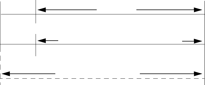
2SHUDWLQJ,QVWUXFWLRQV :DONWHVW
8QLPRGH31&
4.20.5 Alarm Verification (None or Two Minutes)
If alarm verification is selected, an addressable smoke detector's alarm is ignored for a
retard time of 13 seconds and the detector's alarm condition is automatically reset. There
will be no alarm indication at the FACP during the Retard period. A confirmation period
of one minute and 47 seconds follows, during which a subsequent alarm from the same
detector will cause the panel to immediately activate the appropriate outputs and indicate
the alarm condition at the FACP. If a different detector alarms any time during the first
detector's verification period, the panel will immediately activate all appropriate outputs
and indicate the alarm condition at the FACP. If no additional detector alarms occur
within two minutes of the first alarm (13 second retard plus one minute and 47 second
confirmation), the timer resets and the panel is ready to verify any new detector alarms
which may occur.
Note: Alarm Verification is available only for addressable smoke detectors, not
conventional smoke detectors.
4.21 Walktest
Walktest is a feature which allows one person to test the fire alarm system. An audible
walktest will momentarily sound the Notification Appliance Circuits in the building and
store the walktest information in a file at the panel. A silent walktest will not sound the
NACs but will store the walktest information in a file which can be viewed at the panel.
Disabled NAC devices will not activate during walktest.
Alarm/Shorted Condition
When in audible Walktest, the panel responds to each new alarm and activates its
programmed control outputs for four seconds, if those outputs have been programmed for
silenceable activation. It also stores each alarm in the walktest history file which can be
sent to an optional printer. The stored display will be the same as if the device actually
activated except the colon (:) in the time stamp is replaced with an asterisk (*).
Open Condition
Addressable devices as well as both main circuit board NACs are monitored for fault
conditions during Walktest mode. When a new trouble condition occurs, the FACP will
activate all NACs and control modules programmed for Walktest, then shut them off after
eight seconds.
While in Walktest, the trouble relay is activated and the system Trouble LED flashes (as in
all of the Program and status change operations). The alarm relay is not activated.
120 sec.
13 sec.
0 sec.
CONFIRMATION
RETARD
Alarm Ignored Control Panel Processes Alarm if Same Detector is Still in Alarm
Control Panel Immediately Processes Alarm
Detector Alarm Verification
(Retard + Confirmation)
Detector Goes Into Alarm
Different Detector Alarms
During First Detector's
Verification Period
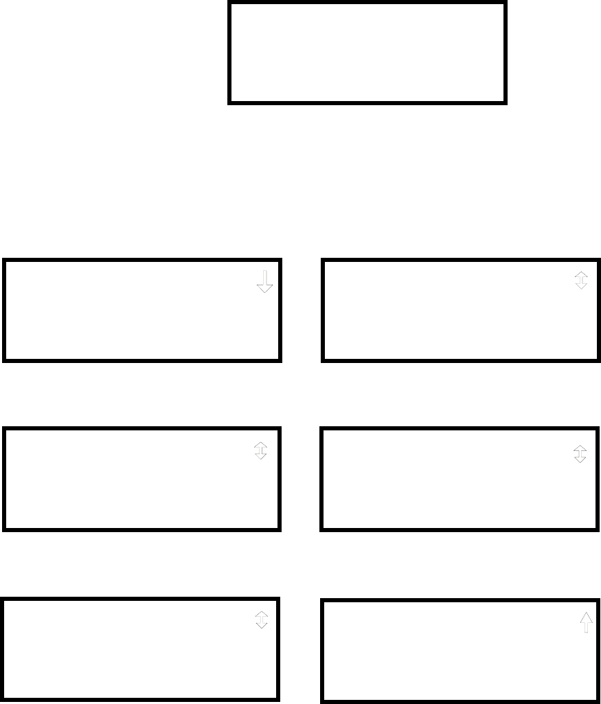
5HDG6WDWXV 2SHUDWLQJ,QVWUXFWLRQV
8QLPRGH31&
4.22 Read Status
Read Status functions do not require a password. The control panel will continue to
provide fire protection while in Read Status mode. This mode can be entered while the
control panel is in alarm or trouble. If a new alarm or trouble occurs during these
functions, the Read Status is exited to prevent confusion.
Read Status Entry
When the operator presses the control panel Enter key, the LCD will display the
following:
Pressing 1, while this screen is being displayed, will cause the control panel to enter the
Read Status mode which allows the user to view and print the programmed features and
status of the control panel.
The following screens will be displayed:
1=READ STATUS
2=PROGRAMMING
READ STATUS
1=SYSTEM POINT
2=ZONES
3=POWER
READ STATUS
1=TROUBLE REMINDER
2=TIMERS
3=NAC
Read Status Screen #1
Read Status Screen #2
READ STATUS
1=RELAYS
2=PROGRAM CHECK
3=HISTORY
Read Status Screen #3
READ STATUS
1=ANNUNCIATORS
2=FUTURE USE
3=FUTURE USE
Read Status Screen #4
READ STATUS
1=FUTURE USE
2=PRINTER/PC
3=PRINT
Read Status Screen #5
READ STATUS
1=TIME-DATE
Read Status Screen #6

2SHUDWLQJ,QVWUXFWLRQV 5HDG6WDWXV
8QLPRGH31&
4.22.1 System Point
Pressing 1 while viewing Read Status Screen #1 will cause the following screen to be
displayed:
The operator selects the loop containing the device to be read by pressing 1 for Loop 1 or
2 for Loop 2. The following screen will then be displayed:
The operator now selects the type of device which is to be viewed by pressing 1 for
Detector or 2 for Module. If 1 is pressed, the display will change to the following screen:
Entering the three digit detector address will cause the control panel to display the current
status of the selected device. For example, if a detector with address 001 on loop 1 is
entered, a display similar to the following will appear:
The information in the preceding display includes:
•NORMAL - the present status (could also be ALARM, TROUBL, DISABL, etc.)
•SMOKE (PHOTO) - the device type which is a photoelectric smoke detector (could
also be ION for ionization smoke detector)
•NORTH CLASSROOM - the Adjective/Noun label for this device
•Z005 - the first of five possible assigned software zones
•1D001 - 1 = Loop 1, D = Detector, 001 = Address 001
READ STATUS
1=SYSTEM POINT
2=ZONES
3=POWER
Read Status Screen #1 READ SYSTEM POINT
SELECT LOOP
1=LOOP 1
2=LOOP 2
READ SYSTEM POINT
SELECT TYPE
1=DETECTOR
2=MODULE
READ SYSTEM POINT
ENTER DETECTOR#
***
NORMAL SMOKE(PHOTO)
NORTH CLASSROOM
Z005
1D001

5HDG6WDWXV 2SHUDWLQJ,QVWUXFWLRQV
8QLPRGH31&
Pressing the down arrow key, while viewing the screen shown above, will allow the
operator to view additional programming information about the selected device, such as:
• Enable/Disable Status
• Device Type
• Alarm Verification On/Off
• Walktest Yes/No
• PAS (Positive Alarm Sequence) Yes/No
• Pre-Signal Yes/No
• Zone Assignments (five maximum)
• Adjective/Noun descriptor
4.22.2 Zones
Pressing 2 while viewing Read Status Screen #1 will cause the following screens to be
displayed:
From the preceding screens, the control panel operator can view:
•Zones Installed - all software zones programmed into the system (99 maximum)
•Zones Enabled - all software zones that are enabled
•Zones Disabled - all software zones that have been disabled
•Special Purpose - on or off programming for Special Purpose Zones 97 reserved for
PAS, 98 reserved for Pre-signal and 99 reserved for future use
•Zone Type - the Type assigned to each installed zone (default is Alarm)
READ STATUS
1=SYSTEM POINT
2=ZONES
3=POWER
Read Status Screen #1 ZONES
1=ZONES INSTALLED
2=ZONES ENABLED
3=ZONES DISABLED
Zones Screen #1
ZONES
1=SPECIAL PURPOSE
2=ZONE TYPE
Zones Screen #2

2SHUDWLQJ,QVWUXFWLRQV 5HDG6WDWXV
8QLPRGH31&
4.22.3 Power
Pressing 3 while viewing Read Status Screen #1 will cause the following screens to be
displayed:
A real-time display of the control panel voltages can be used to determine if a problem
exists in the system.
The following table lists the circuit being measured, possible conditions and their
respective voltage ranges:
4.22.4 Trouble Reminder
Pressing 1 while viewing Read Status Screen #2 will display the following screen:
The screen indicates whether the Trouble Reminder feature is On or Off.
Circuit Condition Voltage Range
Battery
Normal Battery (nominal) 27.05 - 28.15 VDC
Low Battery 20.0 - 20.8 VDC
No Battery 0 - 18.36 VDC
24V Resettable Normal 21.25 - 27.50 VDC
24V Nonresettable Normal 21.25 - 27.50 VDC
Charger Normal 27.05 - 28.15 VDC
NAC 1 or NAC 2
Normal 1.37 - 1.43 VDC
Open Circuit 2.30 - 2.40 VDC
Short Circuit 0 - 1.0 VDC
POWER
BATTERY 27.21V
24 V RST 25.31
24 V NRST 25.31
Zones Screen #1
POWER
CHARGER 28.36V
NAC 1 2.39V
NAC 2 2.39V
Zones Screen #2
READ STATUS
1=TROUBLE REMINDER
2=TIMERS
3=NAC
Read Status Screen #2
TROUBLE REMINDER
TROUBLE REM ON

5HDG6WDWXV 2SHUDWLQJ,QVWUXFWLRQV
8QLPRGH31&
4.22.5 Timers
Pressing 2 while viewing Read Status Screen #2 will cause the following Timer screens to
be displayed:
These screens will indicate the delay time, in seconds, for each of four possible delay
options.
4.22.6 NAC
Pressing 3 while viewing Read Status Screen #2 will display the following screen:
The operator can press 1 to view the programmed options for NAC 1 or 2 to view the
programmed options for NAC 2. The resulting screens will display the following
information:
• Enable/Disable Status
• Circuit Type (Bell, Strobe, etc.)
• Silenceable/Nonsilenceable
• Auto Silence Enable/Disable and time delay
• Coding Selection (Temporal, Steady, etc.)
• Zone Assignments
• Silence Inhibit Enabled/Disabled
• Synchronization Type (System Sensor, Wheelock or Gentex)
TIMERS
PAS DELAY 000
PRE SIGNAL 000
WATERFLOW 000
TIMERS
AC LOSS DELAY 4
NAC
1=NAC 1
2=NAC 2

2SHUDWLQJ,QVWUXFWLRQV 5HDG6WDWXV
8QLPRGH31&
4.22.7 Relays
Pressing 1 while viewing Read Status Screen #3 will display the following screen:
The operator can view the programmed option for each relay by pressing the
corresponding number key.
4.22.8 Program Check
Pressing 2 while viewing Read Status Screen #3 will cause a screen similar to the
following to be displayed:
Pressing 1 while viewing the Program Check screen will display a screen which will
indicate if any input zones have not been programmed to one of the Notification
Appliance Circuits. Use the up and down arrow keys to view both NACs.
Pressing 2 while viewing the Program Check screen will display a screen which will
indicate if any output zones have not been programmed to at least one input zone. Use the
up and down arrow keys to view all zones.
Pressing 3 while viewing the Program Check screen will display a screen which will
indicate if any input zones have not been programmed to at least one output zone. Use the
up and down arrow keys to view all zones.
4.22.9 History
Pressing 3 while viewing Read Status Screen #3 will display the following screen:
The operator can view all events which have been stored in the history file, only alarms or
other events, such as troubles or supervisories, by pressing the corresponding number key.
READ STATUS
1=RELAYS
2=PROGRAM CHECK
3=HISTORY
Read Status Screen #3
RELAY
1=RELAY 1
2=RELAY 2
3=RELAY 3
PROGRAM CHECK
1=NACS NO INPUT
2=ZONES NO INPUT
3=ZONES NO OUTPUT
HISTORY
1=VIEW ALL
2=VIEW ALARMS
3=VIEW OTHER EVENTS

5HDG6WDWXV 2SHUDWLQJ,QVWUXFWLRQV
8QLPRGH31&
4.22.10 Annunciators
Pressing 1 while viewing Read Status Screen #4 will display the following screens:
Annunciator Screen #1 indicates if Terminal Mode, ACS Mode and UDACT options are
enabled or disabled. Pressing ‘1’ while viewing Annunciator Screen #2 allows the
operator to view the ACS Mode Annunciator addresses which have been programmed into
the control panel.
4.22.11 Printer/PC
Pressing 2 while viewing Read Status Screen #5 will display the following screens:
The display will inform the operator as to whether the control panel is configured for a
printer or a PC. In the example above, PR4800 indicates that the panel is configured for a
printer with a baud rate of 4,800.
READ STATUS
1=ANNUNCIATORS
2=FUTURE USE
3=FUTURE USE
Read Status Screen #4 ANNUNCIATORS
TERM ENABLED YES
ACS ENABLED YES
UDACT ENABLED NO
ANNUNCIATORS
1=ACS ADDRESS
Annunciator Screen #1
Annunciator Screen #2
READ STATUS
1=FUTURE USE
2=PRINTER/PC
3=PRINT
Read Status Screen #5 PRINTER PC
PRINTER PC PR4800
START BIT
STOP BIT
PRINTER PC
DATA BITS
PARITY

2SHUDWLQJ,QVWUXFWLRQV 5HDG6WDWXV
8QLPRGH31&
4.22.12 Print
To print program data or control panel status, press 3 while viewing Read Status Screen
#5. The following screens will be displayed:
Pressing 1 while viewing Print Screen #1 allows the user to print the History file which
will detail all of the system activities since the file was last cleared from memory.
Pressing 2 while viewing Print Screen #1 allows the user to print the Walktest log which
will detail all of the system activations during walktest since the log was last cleared.
Refer to "Walktest" on page 90 for additional information on the display.
Pressing 3 while viewing Print Screen #1 allows the user to print the data of each
addressable smoke detector connected to the system. A printout, similar to the following
example, will be generated if an optional printer is connected to the FACP.
Chamber Value
The Chamber value should be within the indicated range for the following smoke
detectors:
• SD350(T), D350P(R) and SD300(T) Addressable Photoelectric Smoke Detectors:
405 - 2100 (obscuration of 1.00%/ft. to 3.66%/ft.)
• CP350 and CP300 Addressable Ionization Smoke Detectors: 750 - 2100
(obscuration of 0.50%/ft. to 1.44%/ft.)
If the addressable smoke detector’s Chamber reading is not within the acceptable range,
clean the detector and check the Chamber value again. If the reading is still not within the
acceptable range, immediately replace the detector.
PRINT
1=HISTORY
2=WALKTEST LOG
3=DETECTOR DATA
PRINT
1=EXIT PRINTING
Print Screen #2
Print Screen #1
DEVICE# DEVICE TYPE %DRIFT COMP CHAMBER TIME/DATE
1D001 SMOKE (PHOTO) 20 1281 12:01AM 01-08-2001
1D002 SMOKE (PHOTO) 20 1281 12:01AM 01-08-2001
1D003 SMOKE (PHOTO) 21 1259 12:01AM 01-08-2001
1D004 SMOKE (PHOTO) 20 1309 12:02AM 01-08-2001
1D005 SMOKE (PHOTO) 21 1281 12:02AM 01-08-2001
1D006 SMOKE (PHOTO) 20 1322 12:02AM 01-08-2001
1D007 SMOKE (PHOTO) 20 1280 12:02AM 01-08-2001
1D008 SMOKE (PHOTO) 20 1215 12:02AM 01-08-2001
1D009 SMOKE (PHOTO) 20 1310 12:02AM 01-08-2001
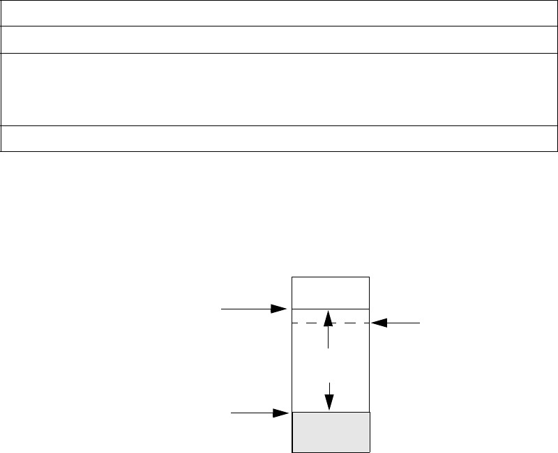
5HDG6WDWXV 2SHUDWLQJ,QVWUXFWLRQV
8QLPRGH31&
Drift Compensation
Drift compensation uses software algorithms that identify and compensate for long-term
changes in the data readings from each addressable smoke detector. These long-term
changes in detector data readings are typically caused by dirt and dust accumulation inside
the smoke chamber. Drift compensation performs the following functions:
• Allows a smoke detector to retain its original ability to detect actual smoke and
resist false alarms, even as dirt and dust accumulate
• Reduces maintenance requirements by allowing the control panel to automatically
perform the periodic sensitivity measurements required by NFPA Standard 72
The FACP software also provides smoothing filters to remove transient noise signals,
usually caused by electrical interference.
Maintenance Alert
The software determines when the drift compensation for a detector reaches an
unacceptable level that can compromise detector performance. When a detector reaches
an unacceptable level, the control panel indicates a maintenance alert. Table 4.1
summarizes the three levels of maintenance alert:
Figure 4.1 illustrates a graphic representation of the maintenance levels:
Maintenance Level FACP Status Display Indicates
Low Chamber Value INVREP A hardware problem in the detector
Maintenance Alert DIRTY1 Dust accumulation that is near but below the
allowed limit. DIRTY 1 indicates the need for
maintenance before the performance of the detector
is compromised
Maintenance Urgent DIRTY2 Dust accumulation above the allowed limit.
Table 4.1 Maintenance Alert Levels
Figure 4.1 Diagram of Maintenance Levels
DIRTY
Acceptable
Range
Maintenance
Urgent Maintenance
Alert
Low Chamber
Reading LOW
VA L U E

2SHUDWLQJ,QVWUXFWLRQV 5HDG6WDWXV
8QLPRGH31&
4.22.13 Time-Date
The operator can view the daylight savings time and the month and week when daylight
savings time will begin and end. Pressing 1 while viewing Read Status Screen #6 will
display the following screens:
READ STATUS
1=TIME-DATE
Read Status Screen #6
DAYLIGHT SAVINGS
ENABLED YES
START MONTH APR
START WEEK WEEK-1
DAYLIGHT SAVINGS
END MONTH OCT
END WEEK LAST-W

Overview Power Supply Calculations
Unimode 9600 PN 51336:C 11/06/01 127
SECTION 5 Power Supply Calculations
5.1 Overview
This section contains instructions and tables for calculating power supply currents in
alarm and standby conditions. This is a four-step process, consisting of the following:
1. Calculating the total amount of AC branch circuit current required to operate the
system
2. Calculating the power supply load current for non-fire and fire alarm conditions and
calculating the secondary (battery) load
3. Calculating the size of batteries required to support the system if an AC power loss
occurs
4. Selecting the proper batteries for your system
5.2 Calculating the AC Branch Circuit
The control panel requires connection to a separate, dedicated AC branch circuit, which
must be labeled FIRE ALARM. This branch circuit must connect to the line side of the
main power feed of the protected premises. No other non-fire alarm equipment may be
powered from the fire alarm branch circuit. The branch circuit wire must run
continuously, without any disconnect devices, from the power source to the control panel.
Overcurrent protection for this circuit must comply with Article 760 of the National
Electrical Codes as well as local codes. Use 14 AWG (2.00 mm2) wire with 600 volt
insulation for this branch circuit.
Use Table 5.1 , to determine the total amount of current, in AC amperes (A), that must be
supplied to the system.
Table 5.1 120 VAC Branch Circuit Requirements
Device Type Number of
Devices
Current Draw
(AC amps)
Total Current
per Device
Unimode 9600 1 X 3.2 = 3.2
ADT-CHG-120 [ ] X 2.0 =
[ ] X [ ] =
Sum Column for AC Branch Current Required =

3RZHU6XSSO\&DOFXODWLRQV &DOFXODWLQJWKH6\VWHP&XUUHQW'UDZ
8QLPRGH31&
5.3 Calculating the System Current Draw
5.3.1 Overview
7KHFRQWUROSDQHOPXVWEHDEOHWRSRZHUDOOLQWHUQDODQGH[WHUQDOGHYLFHVFRQWLQXRXVO\
GXULQJWKHQRQILUHDODUPFRQGLWLRQ7RFDOFXODWHWKHQRQILUHDODUPORDGRQWKHV\VWHP
SRZHUVXSSO\ZKHQSULPDU\SRZHULVDSSOLHGXVH&DOFXODWLRQ&ROXPQLQ7DEOHRQ
SDJH7KHFRQWUROSDQHOPXVWVXSSRUWDODUJHUORDGFXUUHQWGXULQJDILUHDODUPFRQGL
WLRQ7RFDOFXODWHWKHILUHDODUPORDGRQWKHSRZHUVXSSO\XVH&DOFXODWLRQ&ROXPQLQ
7DEOHRQSDJH7KHVHFRQGDU\SRZHUVRXUFHEDWWHULHVPXVWEHDEOHWRSRZHUWKH
V\VWHPGXULQJDSULPDU\SRZHUORVV7RFDOFXODWHWKHQRQILUHDODUPORDGRQWKHVHFRQGDU\
SRZHUVRXUFHXVH&DOFXODWLRQ&ROXPQLQ7DEOHRQSDJH
:KHQFDOFXODWLQJFXUUHQWGUDZDQGWKHEDWWHU\VL]HQRWHWKHIROORZLQJ
µ3ULPDU\¶UHIHUVWRWKHPDLQSRZHUVRXUFHIRUWKHFRQWUROSDQHO
µ6HFRQGDU\¶UHIHUVWRWKHFRQWUROSDQHO¶VEDFNXSEDWWHULHV
$OOFXUUHQWVDUHJLYHQLQDPSHUHV$7DEOHVKRZVKRZWRFRQYHUWPLOOLDP
SHUHVDQGPLFURDPSHUHVWRIXOODPSHUHV
5.3.2 How to Use Table 5.3 on page 129 to Calculate System
Current Draw
Use Table 5.3 on page 129 to calculate current draws as follows:
1. Enter the quantity of devices in all three columns
2. Enter the current draw where required. Refer to the ADT Device Compatibility
Document for compatible devices and their current draw
3. Calculate the current draws for each in all columns
4. Sum the total current for each column
5. Copy the totals from Column 2 and Column 3 to Table 5.4 on page 130
Following are the types of current that can be entered into Table 5.3 on page 129:
✓Calculation Column 1 - The primary supply current load that the control panel
must support during a non-fire alarm condition, with AC power applied.
✓Calculation Column 2 - The primary supply current load that the control panel
must support during a fire alarm condition, with AC power applied.
✓Calculation Column 3 - The standby current drawn from the batteries in a non-
fire alarm condition during a loss of AC power.
Table 5.2 Converting to Full Amperes
7RFRQYHUW 0XOWLSO\ ([DPSOH
0LOOLDPSHUHVP$WR
DPSHUHV$ P$[ P$[ $
0LFURDPSHUHV$WR
DPSHUHV$ $[ $[ $

&DOFXODWLQJWKH6\VWHP&XUUHQW'UDZ 3RZHU6XSSO\&DOFXODWLRQV
8QLPRGH31&
Table 5.3 contains columns for calculating current draws. For each column, calculate the
current and enter the total (in amperes) in the bottom row. When finished, copy the totals
from Calculation Column 2 and Calculation Column 3 to Table 5.4 on page 130.
Table 5.3 System Current Draw Calculations
'HYLFH7\SH
&DOFXODWLRQ&ROXPQ
3ULPDU\1RQ)LUH$ODUP&XUUHQW
DPSV
&DOFXODWLRQ&ROXPQ
3ULPDU\)LUH$ODUP&XUUHQW
DPSV
&DOFXODWLRQ&ROXPQ
6HFRQGDU\1RQ)LUH$ODUP&XUUHQW
DPSV
4W\ ;>FXUUHQWGUDZ@ 7RWDO 4W\ ;>FXUUHQWGUDZ@ 7RWDO 4W\ ;>FXUUHQWGUDZ@ 7RWDO
0DLQ&LUFXLW%RDUG ;>@ ;>@ ;>@
6/&([SDQGHU0RGXOH >@ ;>@ >@ ;>@ >@ ;>@
$'7$&05 >@ ;>@ >@ ;>@ >@ ;>@
$'7$&0$7
$'7$&0$ >@ ;>@ >@ ;>@ >@ ;>@
$(0$7
$(0$ >@ ;>@ >@ ;>@ >@ ;>@
$'7$)0$7
$'7$)0$ >@ ;>@ >@ ;>@ >@ ;>@
$'7$)0$ >@ ;>@ >@ ;>@ >@ ;>@
$'78'$&7 >@
PD[ ;>@ >@ ;>@ >@ ;>@
$'7/'0 >@ ;>@ >@ ;>@ >@ ;>@
$'7/'0( >@ ;>@ >@ ;>@ >@ ;>@
$'7/&') >@ ;>@ >@ ;>@ >@ ;>@
;70) >@ ;>@ >@ ;>@ >@ ;>@
ZLUH'HWHFWRU+HDGV >@ ;>@ >@ ;>@ >@ ;>@
3RZHU6XSHUYLVLRQ
5HOD\V>@ ;>@ >@ ;>@ >@ ;>@
&3 >@ ;>@
PD[LPXPDODUPGUDZ
IRUDOOGHYLFHV
>@ ;>@
6' >@ ;>@ >@ ;>@
6'7 >@ ;>@ >@ ;>@
+ >@ ;>@ >@ ;>@
+5 >@ ;>@ >@ ;>@
'3 >@ ;>@ >@ ;>@
'53 >@ ;>@ >@ ;>@
%%+%%+7>@ ;>@ >@ ;>@
%5%5HOD\%DVH >@ ;>@ >@ ;>@
%%,,VRODWRU%DVH >@ ;>@ >@ ;>@
00) >@ ;>@ >@ ;>@
0') >@ ;>@ >@ ;>@
00) >@ ;>@ >@ ;>@
00) >@ ;>@ >@ ;>@
%*/; >@ ;>@ >@ ;>@
&0) >@ ;>@ >@ ;>@
&5) >@ ;>@ >@ ;>@
, >@ ;>@ >@ ;>@
1$&>@ ;>@
1$& >@ ;>@
&XUUHQW'UDZIURP7%
QRQDODUP>@ >@ >@ >@ >@
6XPHDFKFROXPQ
IRUWRWDOV 3ULPDU\1RQ$ODUP 3ULPDU\$ODUP 6HFRQGDU\$ODUP
Table Footnote
1. All eight ADT-ACM-8R relays activated on a single module.
2. All annunciator LEDs on
3. ADT-UDACT actively making phone call to central station. If the normally open contact is used, current
consumption increases to 100 mA.
4. ADT-LDM-32 with LEDs on
5. If using the Reverse Polarity Alarm output, add 0.005 amps; if using the Reverse Polarity Trouble output, add
another 0.005 amps.
6. Refer to the Device Compatibility Document for standby current.
7. Must use compatible listed Power Supervision Relay.
8. Maximum alarm current for each sounder base is 0.015 amps which must be supplied by aux. 24 VDC source.
9. Current limitation of Terminal TB4 circuits is 3.00 amps per NAC.
10.The total standby current must include both the resettable (TB3 Terminals 1 & 2) and nonresettable (TB3
Terminals 3 & 4, 5 & 6) power. Caution must be taken to ensure that current drawn from these outputs during
alarm does not exceed maximum ratings specified. Current limitations of TB3 circuits is 3.0 amps per output
11.Total current draw listed above cannot exceed 7.2 amps.

3RZHU6XSSO\&DOFXODWLRQV &DOFXODWLQJWKH%DWWHU\6L]H
8QLPRGH31&
5.4 Calculating the Battery Size
Use Table 5.4 to calculate the total Standby and Alarm load in ampere hours (AH). This
total load determines the battery size (in AH), required to support the control panel under
the loss of AC power. Complete Table 5.4 as follows:
1. Enter the totals from Table 5.3 on page 129, Calculation Columns 2 and 3 where
shown
2. Enter the NFPA Standby and Alarm times (refer to ‘NFPA Requirements’ below)
3. Calculate the ampere hours for Standby and Alarm, then sum the Standby and
Alarm ampere hours
4. Multiply the sum by the derating factor of 1.2 to calculate the proper battery size (in
AH)
5. Write the ampere hour requirements on the Protected Premises label located inside
the cabinet door
5.4.1 NFPA Battery Requirements
• NFPA 72 Local and Proprietary Fire Alarm Systems require 24 hours of standby
power followed by 5 minutes in alarm
• NFPA 72 Central, Auxiliary and Remote Station Fire Alarm Systems require 60
hours of standby followed by 5 minutes in alarm. Batteries installed in a system
powered by a generator need to provide at least 4 hours of standby power
• NFPA requires 24 hours of standby plus 15 minutes activation for audio systems.
The total ampere hours required cannot exceed 25 AH with an internal charger
5.4.2 Selecting and Locating Batteries
Select batteries that meet or exceed the total ampere hours calculated in Table 5.4 . The
control panel can charge batteries in the 7 AH to 25 AH range. The control panel cabinet
is capable of housing batteries up to 18 AH. Batteries larger than 18 AH require the BB-
55F or other UL listed external battery cabinet.
Table 5.4 Total Secondary Power Requirements at 24 VDC
6HFRQGDU\6WDQGE\/RDG
WRWDOIURP7DEOH&DOFXODWLRQ
&ROXPQ
>@
5HTXLUHG6WDQGE\7LPH
RUKRXUV
;>@ $+
3ULPDU\$ODUP/RDG
WRWDOIURP7DEOH&DOFXODWLRQ
&ROXPQ
>@
5HTXLUHG$ODUP7LPH
IRUPLQHQWHU
IRUPLQHQWHU
;>@ $+
6XPRI6WDQGE\DQG$ODUP$PSHUH+RXUV $+
0XOWLSO\E\WKH'HUDWLQJ)DFWRU ;
%DWWHU\6L]H7RWDO$PSHUH+RXUV5HTXLUHG $+
&RUUHODWLRQV 6RIWZDUH=RQHV
8QLPRGH31&
APPENDIX A 6RIWZDUH=RQHV
A.1 Correlations
Setup and configuration of an addressable system is different than a conventional system.
In a conventional system, assignment of input devices (smoke detectors, pull stations, heat
detectors, etc.) to zones is accomplished through wiring. The wiring is direct from clearly
marked panel terminals to any device assigned to a particular zone. Connection of output
devices (horns, bells, strobes, etc.) in a conventional system is accomplished by direct
wiring of the output devices to Notification Appliance Circuit terminals.
In an addressable system, a minimum of a single pair of wires (SLC communication loop)
is used to connect all addressable input and output devices. Communications between the
FACP (Fire Alarm Control Panel) and all addressable devices takes place over the wire
pair which originates from the FACP. Software programming is used to configure the
system as opposed to direct wiring. Zone assignments are created via software means,
hence the term software zones.
Setup of an Unimode 9600 software zone is accomplished by panel programming. Each
addressable device can be assigned to a maximum of five software zones. Each software
zone, however, may have from 1 to 99 addressable input devices assigned to it and from 1
to 99 addressable output devices assigned to it.
Monitor and control modules comprise one group of 99 addresses, with each module
having a unique address from 1 to 99. Detectors comprise a separate group of 99
addresses, each detector having a unique address from 1 to 99 in its group. Be careful not
to duplicate addresses within any one group (modules and detectors). Refer to the
following page for an example of zoning.
In the example on the following page:
• Zone 01 has the following addressable devices assigned to it:
✓SD350 smoke detectors with addresses 01 and 02
✓MMF-300 monitor module with address 01
✓MMF-302 monitor module with address 02 and 03
✓CMF-300 control modules with addresses 05, 06, 07, 09 and 13
• Zone 02 has the following addressable devices assigned to it:
✓MMF-302 monitor module with addresses 02 and 03
✓CP350 smoke detectors with addresses 03 and 04
✓CMF-300 control modules with addresses 08, 09 and 10
• Zone 03 has the following addressable devices assigned to it:
✓SD350 smoke detectors with addresses 05, 06 and 07
✓MMF-302 control module with address 04
✓CMF-300 control modules with addresses 09, 11 and 12
The example points out some of the key assignment features of the Unimode 9600.
Addresses of detectors are not duplicated. Addresses of monitor and control modules are
not duplicated. The control module with address 09 is assigned to three software zones
(providing floor above and floor below). Be careful to properly plan the installation prior
to installing any devices.
CLIP or Classic Loop Interface Protocol devices (modules and detectors) can only have
unique addresses of 1 to 99. Newer modules can have unique addresses of 1 to 159 which
means each zone can have up to 159 input and output devices assigned to it.
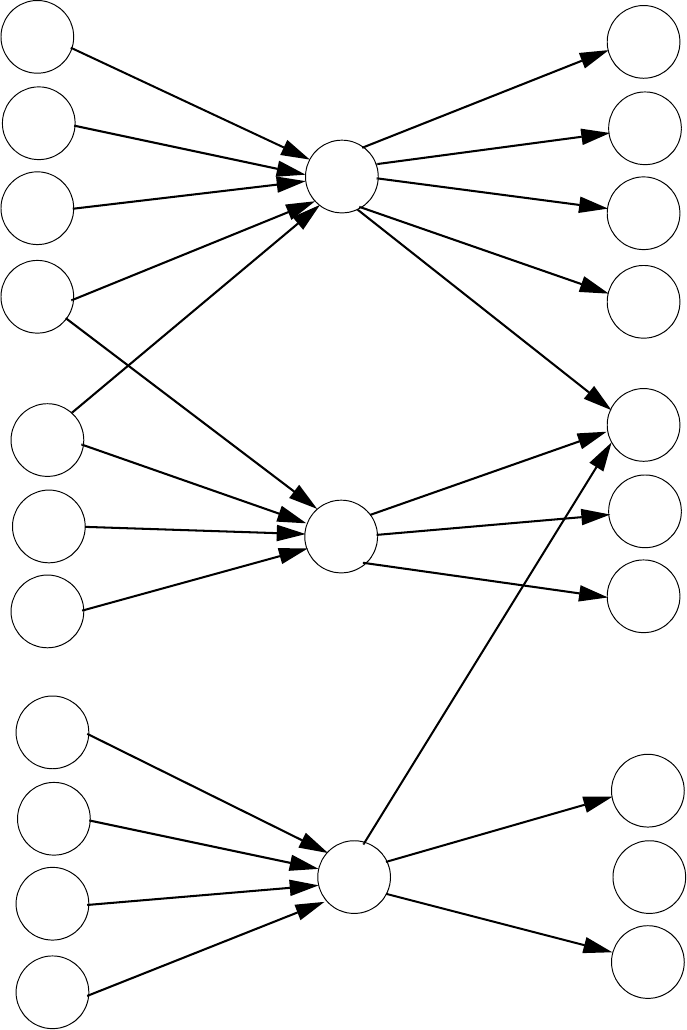
6RIWZDUH=RQHV &RUUHODWLRQV
8QLPRGH31&
Correlation of Input and Output Zones
The zone correlations which are shown graphically above are also presented in Table A.1
on page 133 and Table A.2 on page 134.
Input Devices Zones Output Devices
ZONE
01
ZONE
02
ZONE
03
SD350
01
SD350
02
MMF-300
01
MMF-302
02
MMF-302
03
CP350
03
CP300
04
SD350
05
SD350
06
SD350
07
MMF-302
04
CMF-300
06
CMF-300
05
CMF-300
07
CMF-300
09
CMF-300
08
CMF-300
10
CMF-300
11
CMF-300
12
CMF-300
13

&RUUHODWLRQV 6RIWZDUH=RQHV
8QLPRGH31&
7DEOH$'HWHFWRU3URJUDPPLQJ6KHHW([DPSOH
DETECTOR ZONE ASSIGNMENT
Address Device
Type
Zone
Number
ADJ/NOUN Address Device
Type
Zone
Number
ADJ/NOUN
01 SD350 1 FIRST HALL 51
02 SD350 1 ELEV. LOBBY 52
03 CP350 2 2ND FLOOR 53
04 CP350 2 ROOM 210 54
05 SD350 3 3RD FLOOR 55
06 SD350 3 MEZZANINE 56
07 SD350 3 MECH. ROOM 57
08 58
09 59
10 60
11 61
12 62
13 63
14 64
15 65
16 66
17 67
18 68
19 69
20 70
21 71
22 72
23 73
24 74
25 75
26 76
27 77
28 78
29 79
30 80
31 81
32 82
33 83
34 84
35 85
36 86
37 87
38 88
39 89
40 90
41 91
42 92
43 93
44 94
45 95
46 96
47 97
48 98
49 99
50 100

6RIWZDUH=RQHV &RUUHODWLRQV
8QLPRGH31&
7DEOH$0RGXOH3URJUDPPLQJ6KHHW([DPSOH
MONITOR/CONTROL MODULE ZONE ASSIGNMENT
Address Device
Type
Zone
Number
ADJ/
NOUN
Address Device
Type
Zone
Number
ADJ/NOUN
01 MMF-300 1 51
02 MMF-302 1, 2 52
03 MMF-302 1, 2 53
04 MMF-302 3 54
05 CMF-300 1 55
06 CMF-300 1 56
07 CMF-300 1 57
08 CMF-300 2 58
09 CMF-300 1, 2, 3 59
10 CMF-300 2 60
11 CMF-300 3 61
12 CMF-300 3 62
13 CMF-300 1 63
14 64
15 65
16 66
17 67
18 68
19 69
20 70
21 71
22 72
23 73
24 74
25 75
26 76
27 77
28 78
29 79
30 80
31 81
32 82
33 83
34 84
35 85
36 86
37 87
38 88
39 89
40 90
41 91
42 92
43 93
44 94
45 95
46 96
47 97
48 98
49 99
50 100

&RUUHODWLRQV 6RIWZDUH=RQHV
8QLPRGH31&
7DEOH$%ODQN'HWHFWRU3URJUDPPLQJ6KHHWRI
DETECTOR ZONE ASSIGNMENT
Address Device
Type
Zone
Number
ADJ/
NOUN
Address Device
Type
Zone
Number
ADJ/NOUN
01 51
02 52
03 53
04 54
05 55
06 56
07 57
08 58
09 59
10 60
11 61
12 62
13 63
14 64
15 65
16 66
17 67
18 68
19 69
20 70
21 71
22 72
23 73
24 74
25 75
26 76
27 77
28 78
29 79
30 80
31 81
32 82
33 83
34 84
35 85
36 86
37 87
38 88
39 89
40 90
41 91
42 92
43 93
44 94
45 95
46 96
47 97
48 98
49 99
50 100

6RIWZDUH=RQHV &RUUHODWLRQV
8QLPRGH31&
7DEOH$%ODQN'HWHFWRU3URJUDPPLQJ6KHHWRI
DETECTOR ZONE ASSIGNMENT
Address Device
Type
Zone
Number
ADJ/
NOUN
Address Device
Type
Zone
Number
ADJ/NOUN
101 151
102 152
103 153
104 154
105 155
106 156
107 157
108 158
109 159
110
111
112
113
114
115
116
117
118
119
120
121
122
123
124
125
126
127
128
129
130
131
132
133
134
135
136
137
138
139
140
141
142
143
144
145
146
147
148
149
150

&RUUHODWLRQV 6RIWZDUH=RQHV
8QLPRGH31&
7DEOH$%ODQN0RGXOH3URJUDPPLQJ6KHHWRI
MONITOR/CONTROL MODULE ZONE ASSIGNMENT
Address Device
Type
Zone
Number
ADJ/
NOUN
Address Device
Type
Zone
Number
ADJ/NOUN
01 51
02 52
03 53
04 54
05 55
06 56
07 57
08 58
09 59
10 60
11 61
12 62
13 63
14 64
15 65
16 66
17 67
18 68
19 69
20 70
21 71
22 72
23 73
24 74
25 75
26 76
27 77
28 78
29 79
30 80
31 81
32 82
33 83
34 84
35 85
36 86
37 87
38 88
39 89
40 90
41 91
42 92
43 93
44 94
45 95
46 96
47 97
48 98
49 99
50 100

6RIWZDUH=RQHV &RUUHODWLRQV
8QLPRGH31&
7DEOH$%ODQN0RGXOH3URJUDPPLQJ6KHHWRI
MONITOR/CONTROL MODULE ZONE ASSIGNMENT
Address Device
Type
Zone
Number
ADJ/
NOUN
Address Device
Type
Zone
Number
ADJ/NOUN
101 151
102 152
103 153
104 154
105 155
106 156
107 157
108 158
109 159
110
111
112
113
114
115
116
117
118
119
120
121
122
123
124
125
126
127
128
129
130
131
132
133
134
135
136
137
138
139
140
141
142
143
144
145
146
147
148
149
150

&RUUHODWLRQV 'HIDXOW3URJUDPPLQJ
8QLPRGH31&
APPENDIX B 'HIDXOW3URJUDPPLQJ
The following table provides a list of the programming options and their factory default
settings.
Program Option Factory Default Program Option Factory Default
Detector Programming Not Installed Daylight Savings Yes
Detector Type Smoke-Photo Month Start Daylight Savings April
Detector Verification Off Week Start Daylight Savings 1st Week
Detector Walktest Yes Month End Daylight Savings October
Detector PAS No Week End Daylight Last Week
Detector Presignal No Verification No
Detector Zone Assign. 000 only (future)
Detector Adj/Noun none PAS Timer 0
Module Programming Not Installed Presignal Timer 0
Module Type Monitor Waterflow Retard Timer 0
Module Walktest Yes NAC 1 & 2 Enable Enabled
Module PAS No NAC 1 & 2 Silenceable Yes
Module Presignal No NAC 1 & 2 Type Bell
Module Zone Assign. 000 only NAC 1 & 2 Sync Type System Sensor
Module Adj/Noun none NAC 1 & 2 Autosilence 0
Zone 0 Enable Enabled NAC 1 & 2 Coding Steady
Zone 1 Enable Enabled NAC 1 & 2 Zones Zone 000 only
Zone 2 Enable Enabled NAC 1 & 2 Silence Inhibit 0
Zone 3 Enable Enabled Relay 1 Alarm
.........................through.......... ..................... Relay 2 Trouble
Zone 96 Enable Enabled Relay 3 Supervisory
Zones 97, 98 & 99 Enabled (future) No
(future) Annunciator Terminal Mode No
Loop 1 & 2 Style Style 4 Annunciator ACS Mode
Loop 1 & 2 Protocol CLIP UDACT No
Trouble Reminder Off ACS Installed No
Banner Fire•Lite Printer-PC No
Time Format 12 Hr Printer Baud 9600
Hours Setting 12
Minutes Setting 00
Second Settings 00
AM-PM Setting AM
Month Setting 01
Day Setting 01
Year Setting 00

:LUH5HTXLUHPHQWV &RUUHODWLRQV
8QLPRGH31&
APPENDIX C :LUH5HTXLUHPHQWV
T-tapping of the SLC loop wiring is allowed for 2-wire (Style 4) configurations. The total
resistance of any branch cannot exceed 40 ohms. The total wire length of all branches
cannot exceed 10,000 feet (3,000 m).
Connecting external system accessories to the Unimode 9600 main circuits must be
carefully considered to ensure proper operation. It is important to use the correct type of
wire, wire gauge and wire run length for each Unimode 9600 circuit. Reference the chart
below to specify wire requirements and limitations for each Unimode 9600 circuit.
Note: If the SLC loop is to be run in conduit with Notification Appliance Circuits, the risk
of encountering problems can be greatly reduced by exclusively employing electronic
sounders (such as MA/SS-24D) instead of more electronically noisy notification
appliances such as electromechanical bells or horns.
7DEOH&8QLPRGH:LUH6SHFLILFDWLRQV
CIRCUIT CONNECTIONS WIRE REQUIREMENTS
Circuit Type Circuit Function Wire Type and Limitations
Recommended
Max. Distance
Feet (meters)
Wire Gauge and Compatible Brands
SLC loop
(power-limited)
Connects to
Addressable
Devices
Twisted, shielded pair, 40
ohms maximum per length
of Style 6 and 7 loops. 40
ohms per branch maximum
for Style 4 loops1
10,000 (3,000 m)
8,000 (2,400 m)
4,875 (1,450 m)
3,225 (980 m)
12 AWG (3.25 mm): Genesis 4410,
Signal 98230, Belden 9583, WPW999
14 AWG (2.00 mm):Genesis 4408 & 4608
Signal 98430, Belden 9581, WPW995
16 AWG (1.30 mm): Genesis 4406 & 4606
Signal 98630, Belden 9575, WPW991
Direct Burial Cable Isotec NP713110VNQ-S
18 AWG (0.75 mm): Genesis 4402 & 4602
Signal 98300, Belden 9574, WPW975
Direct Burial Cable Isotec NP714110VNQ-S
Untwisted, unshielded pair 3,000 (900 m) 12-18 AWG (3.25 - 0.75 mm)
ACS/TERM
(EIA-485)
(power-limited)
Connects to
annunciator
modules and
ADT-UDACT
Twisted, shielded pair with a
characteristic impedance of
120 ohms
6,000 (1,800 m) 18 AWG (0.75 mm)
EIA-232
(power-limited)
connects to
remote printer
and PC computer
Twisted, shielded pair 50 (15 m) 18 AWG (0.75 mm) minimum
MMF-300 and
MMF-301
(power-limited)
Initiating Device
Circuit
Maximum loop wire
resistance is 40 ohms for the
MMF-300 and 20 ohms for
the MMF-301
2,500 (760 m) 12-18 AWG (3.25 - 0.75 mm)
MMF-302
(power-limited)
Initiating Device
Circuit
No more than a 2.4 volt drop
allowed at end of circuit.
Maximum loop wire
resistance is 25 ohms
2,500 (760 m) 12-18 AWG (3.25 - 0.75 mm)
CMF-300
(power-limited)
Notification
Appliance
Circuit
In alarm, no more than a 1.2
volt drop allowed at end of
circuit
Distance limitation
set by 1.2 volt
maximum line
drop
12-18 AWG (3.25 - 0.75 mm)
24 VDC
filtered
resettable
(power-limited)
Connects to
4-wire smoke
detectors
No more than 1.2 volt drop
allowed from supply source
to end of any branch
Distance limitation
set by 1.2 volt
maximum line
drop
12-18 AWG (3.25 - 0.75 mm)
24 VDC
nonresettable
(power-limited)
Connects to
control modules,
annunciators and
accessories
No more than 1.2 volt drop
allowed from supply source
to end of any branch
Distance limitation
set by 1.2 volt
maximum line
drop
12-18 AWG (3.25 - 0.75 mm)
CHG-120F Remote
secondary power
source
12 AWG (3.25 mm) in
conduit
20 (6 m) 12-18 AWG (3.25 - 0.75 mm)
Table Footnote
1. When using untwisted, unshielded wire, full conduit is recommended for optimum EMI/RFI protection.
Unimode 9600 PN 51336:C 09/19/01 141
Index
Numerics
300 Series addressable devices 20
4XTMF module
coil resistance 31
current 31
installation 31
installation steps 32
see also Transmitter Module
13, 20
voltage 31
A
AC Branch Circuit
calculations 127
AC Loss Delay 81
AC Power 27
current 14
current, maximum 27
voltage 14
wiring 14, 27
Acknowledge/Step 16, 105
ACM-8RF 13
contact rating 35
ACS LED annunciator 13
add Detector 43
add Module 53
address range 19
addressable 12
addressable detectors
see also detectors 13
Addressable Device Accessories 20
addressable modules 19
see also modules 13
addressing
annunciators 37
see also module or detector ad-
dressing 19
Adjective
control module 67
monitor module 60
multiple entries 52
Adjective list 50
ADT-ACM-16A Annunciator 22
ADT-ACM-32A Annunciator 22
ADT-ACM-8R 35
mounting to BRKT-9600 36
see also Relay Control Module
35
ADT-ACS LED annunciator 37
ADT-ACS Series
see also annunciator 22
ADT-AFM annunciator 37
ADT-AFM-16A Annunciator 22
ADT-AFM-16AT Annunciator 22
ADT-AFM-32A Annunciator 22
ADT-BG-10LX
see also manual pull station 20
ADT-BG-12LX
see also manual pull station 19
ADT-CHG-120
see also battery charger 22
see also remote battery charger
14
ADT-LCD-80F annunciator 13, 23
ADT-LDM Series annunciator 23
ADT-UDACT
mounting to BRKT-9600 36
programming 35
see also Digital Alarm Commu-
nicator/Transmitter 35
AEM-16AT Annunciator 22
AEM-32A Annunciator 22
Alarm 109
Alarm Silence 16, 105
alarm verification 12, 47, 112, 116
annunciator 22
ACS 13
ADT-ACM-8R 13
ADT-ACS 37
ADT-LCD-80F 13
LDM Graphic 13
annunciator addressing 37
annunciator, graphic
see also ADT- LDM Series 23
annunciator, remote
see also ADT- LCD-80F 23
annunciatorADT-
AFM 37
Auto Silence
NAC 84
Automatic Test Operation 112
Autoprogramming 13, 39, 87
Autosilence 13, 115
auxiliary DC power 27
Auxiliary Trouble Input 17, 32
B
backbox 18
see also cabinet 26
Banner 75
Banner setting 76
battery 18
cable connection 27
charger 17
charger capacity 14
Charging Circuit 14
see also secondary power 14,
27
battery box 21, 22
battery charger 22
disable 14
external 22
baud rate 92
BB-17F
see also battery box 21
BB-55F
see also battery box 18, 22
BRKT-9600
bracket installation 35, 36
see also Universal Bracket 35
C
C304 Control/Relay Module 20
cabinet 18
dimensions 25, 26
cabinet mounting 24
Calculate System Current Draw 128
Calculating the Battery Size 130
Class A 19, 28
Class B 19, 28
Classic Loop Interface Protocol 19
CLIP Mode
see also Classic Loop Interface
Protocol 19
Clock Format 78
CMF-300 control module 19
Coded Operation 113
Coding
NAC 84
Control Buttons 105
control module 19
description display 69
display 63
edit 63
enable/disable 64
noun 68
noun/adjective 66, 67
silenceable 65
type 65
type codes 65
Correlations 131
CP300 Ionization Detector 20
CP350 18
CRF-300 relay module 19
current
AC Power 27
availability 15
maximum 15
Current Draw Calculations 129
D
D350P 18
D350R 18
data
printout 124
see also smoke detector sensi-
tivity 112
Data Entry
via computer keyboard 38
via keypad 38
Date setting 78
Daylight Savings Time 78
DC power
nonresettable 27
resettable 27
142 Unimode 9600 PN 51336:C 09/19/01
Index
see also auxiliary DC power 27
Default Programming 139
Delete Detector 44
Delete Module 54
Description
control module 69
detector label 52
monitor module 62
Detector 13
add 43
adding description 49
delete 44
edit 44
enable/disable 46
screen display 45
type 47
verification 47
Detector Annunciator 19
detector data 124, 125
acceptable range 124
Detector Programming 43
Digital Alarm Communicator/
Transmitter
see also ADT- UDACT 35
dimensions
cabinet 25
DIRTY1 125
DIRTY2 125
Disable 71
Disable Point
Maintenance Level 98
dress panel 18, 21
drift compensation 12
definition 125
Drill 16, 105
E
earth ground 27
edit
control module 63
detector 44
detector screens 45
module, monitor 54
EIA-232 34
for PC/Printer connection 15
see also Printer/PC interface 12
EIA-485
for ACS annunciators 15
for LCD-80F 15
Enable 70
Enable/Disable
control module 64
detector 46
module, monitor 57
End-of-Line Resistor Assembly 20
Enter key 41
Erase History 89
exiting
programming 39, 40
Read Status 39, 40
Expander Module 33
see also SLC-2 20
F
FACP
see also Fire Alarm Control
Panel 12
Features 12
Fire Alarm Control Panel
see also FACP 12
Form-C relay 17, 28, 35
G
general alarm zone 59
see also zone Z00 49
ground fault 34
H
H350 18
H350R 18
Hazard Condition 111
History 88
erase 89
Maintenance Level 99
view events 89
History file 12
I
I300
see also Isolator Module 19
Indicators 16
Installation 24
intelligent 12
Inventory 12
INVREP 125
Isolator Module 19
K
Key Panel 16
function keys 16
service/program keys 16
keyboard and keypad 38
Keypad/Display
removal and installation 30
L
lamp test 16
LCD display 12, 16
LDM-32 Graphic Annunciator 13
LED
AC Power 106
Alarm Silenced 106
Battery 106
Disabled 106
Fire Alarm 106
Ground 106
Maintenance 106
see also Indicators 16
Supervisory 106
Trouble 106
LED annunciator 22
Local Energy Municipal Box Ser-
vice 31
Loop Setup 74
M
M300 Monitor Module 20
M301 Miniature Monitor Module
20
M302 2-wire Monitor Module 20
main circuit, mounting 24
Maintenance Alert 12, 112
maintenance alert 125
levels 125
Maintenance Program Level 2 40,
97
Manual programming 39
Manual Pull Station 19
Master Program Level 1 40, 42
MDF-300 monitor module 19
Medical Alert 111
MMF-300 monitor module 19
MMF-301 monitor module (minia-
ture) 19
MMF-302 monitor module 19
Mode key 41
Module 13
add 53
addressing 19
delete 54
edit monitor 54
enable/disable 57
see also addressable modules
19
Module Programming 53
Monitor module
adjective 60
enable/disable 57
noun 61
noun/adjective 59
type 57
type action 58
Type list 57
type selection 58
monitor module 19
Mounting
cabinet 24
main circuit board 24
municipal box transmitter
see also 4XTMF module 31
N
NAC 14, 17, 81, 111
Auto Silence 84
coded 113
coding 84
current 14
End-of-Line Resistor 14
power 12
see also Notification Appliance
Unimode 9600 PN 51336:C 09/19/01 143
Index
Circuit 12, 28
silence inhibit 85
silenceable 83
synchronized 113
type codes 83
voltage drop 14
voltage, operating 14
wiring diagram 28
wiring Style 28
NAC enable/disable 82
NAC options 75
NAC type 83
N-ELR Mounting Plate 20
NFPA Battery Requirements 130
nonpower-limited
relay connections 28
Nonresettable Power 17, 27
current 14, 27
Normal 107
normal display 39
Notification Appliance Circuit 14,
81
see also NAC 12, 28
Noun
monitor module 61
multiple entries 52
Noun list 51
Noun/Adjective 49, 51
control module 66
monitor module 59
O
Off-line Programming 39
Operating Instructions 105
Operation
alarm 109
disable/enable 112
hazard condition 111
medical alert 111
NAC 111
normal 107
process monitor 111
programmed zone 112
supervisory 110
trouble 107
waterflow 112
Option Modules 20, 30, 91
annunciators/UDACT 91
Printer/PC 92
Options 12
Output Circuits 17
P
PAS 48, 71, 114
see also Positive Alarm Se-
quence 12, 47
selection 59
PAS BYPASS 114
PAS timer 79
Password 13, 40
change 93
Maintenance Level 2 41, 97
password
Master Level 1 41
PC (personal computer)
configuration 34
connection 34
ground fault 34
Piezo
see also sounder 16
PK-9600 Programming Utility 21
Point Program 43
Positive Alarm Sequence 47, 114
see also PAS 12
power
NAC 12
nonresettable 14
resettable smoke 14
system 12
power supply calculations 127
power-limited
relay connections 28
Power-up
first time 40
Pre-signal 12, 48, 71
function 113
selection 59
Pre-signal Delay timer 80
Pre-signal timer 79
primary power
see also AC Power 27
printer
baud rate 92
configuration 34
connection 34
ground fault 34
setup 34
Printer/PC interface 12
Process Monitor 111
Program
check 95
check correlations 95
clear 94
Program Check
Maintenance Level 100
program keys
see also Key Panel 16
Programming 38, 39
autoprogramming 39
exiting 39
factory default 139
Level 1 40
Level 2 40
manual 39
Master Level 1 42
modules 53
off-line computer 39
via computer keyboard 38
via panel keypad 38
Programming Levels 40
Programming Screens 40
Programming Sheet 133, 134, 135,
136, 138
Programming Utility
see also PK-9600 21
PRT/PK-CABLE
for PC/Printer connection 34
R
RA400Z
see also detector annunciator 19
Read Status 39, 117
annunciators 123
exiting 39
history 122
NAC 121
power 120
Print 124
printer/PC 123
program check 122
relay 122
system point 118
Time-Date 126
timers 121
trouble reminder 120
zones 119
Real-Time Clock 112
Recall/Increment Function 52, 62,
69
Relay 14, 17, 28, 86
connections 28
contact rating 14, 17, 28
fixed 28
Form-C 14, 86
programmable 12, 17, 28
programming 86
selections 86
trouble 12, 17, 28
Relay Control Module
see also ADT-ACM-8R 35
relay module 19
Relay options 75
Remote Station Service 31
remote switch functions 13
Reset 16, 105
Resettable Power 17, 27
current 27
see also Smoke Detector Power
14
S
SD300 Photoelectric Detector 20
SD300T Photoelectric Detector 20
SD350 18
SD350T 18
144 Unimode 9600 PN 51336:C 09/19/01
Index
Secondary Power Requirements 130
sensitivity 112
see also detector sensitivity 12
Signal rate 13
Signaling Line Circuit 14
Silence Inhibit 13, 85, 115
Silenceable
control module 65
NAC 83
SLC 13, 14, 17
current 14
reference manual 14
resistance 14
see also Signaling Line Circuit
12
Style 17
voltage 14
wiring length 14
SLC Loop Protocol 74
SLC loop selection 43
SLC Style 74
SLC-2 33
installation 33
wiring 33
SLC-2 Expander Module 20
smoke detector
chamber reading 124
data 124
sensitivity 112
Smoke Detector Power
current 14
smoke detector sensitivity 12
Software Zones 12, 131
sounder 16
Specifications 14
strobe synchronization 13
Style 12
Style B 19
Style D 19
Style Y 19, 28
Style Z 19, 28
subscreen 40
Supervisory 110
sync
programming 82
see also synchronization 85
synchronization 113, 121
by manufacturer 85
programming 85
see also strobe synchronization
13
Synchronized Signals 113
System
Maintenance Level 101
System Point 118
system power 12
System Setup 75
T
The 35
Time and Date
Maintenance Level 102
Time setting 77
Time-Date setting 75, 77
Timers 75
Transmitter Module 31
see also 4XTMF module 20
Trouble 107
trouble display 108
trouble relay 12
Trouble Reminder 75, 115, 120
trouble responses 108
Type
control module 65
detector 47
monitor module 57
NAC 83
type code
control module 65
supervision 112
type-code
verification 12
U
UL power-limited wiring require-
ments 29
see also power-limited and non-
power-limited 28
Universal Bracket
see also BRKT-9600 35
V
Verification
detector 47
Verify Loops 88
View Events 89
voltage
measurements 120
ranges 120
W
Walktest 12, 47, 66, 90
audible 90
Maintenance Level 101
operation 116
selection 59
silent 90
Waterflow Delay timer 79, 80
Waterflow Retard Timer 115
Wire Requirements 140
wiring
AC Power 27
earth ground 27
SLC-2 33
wiring control modules
see also Style Y or Style Z 19
wiring modules
see also Style B or Style D 19
wiring Style 12
Z
Z00 49, 59
Z97
PAS zone 48
Z98 48
Zone 97 71
Zone 98 71
Zone Assignment 49, 59
control module 66
Zone assignment 85
Zone Setup 70
Maintenance Level 103
zone type 73
list 73
Zone Z97 48
Zone Z98
pre-signal zone 48
Zones 119, 131
see also software zones 12
Zones Disabled 72
Zones Enabled 72
Zones Installed 72
zones per device 49
8QLPRGH31&
Notes
8QLPRGH31&
Notes
8QLPRGH31&
Notes
