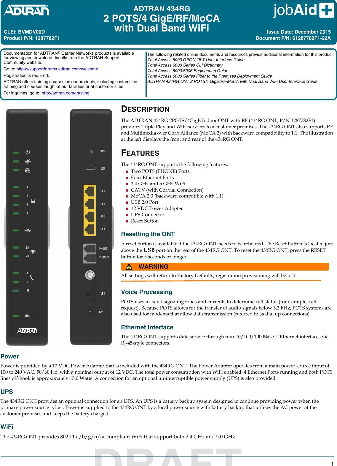
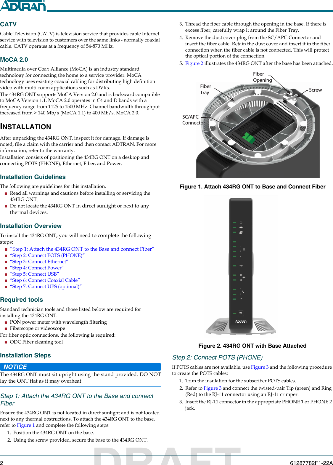
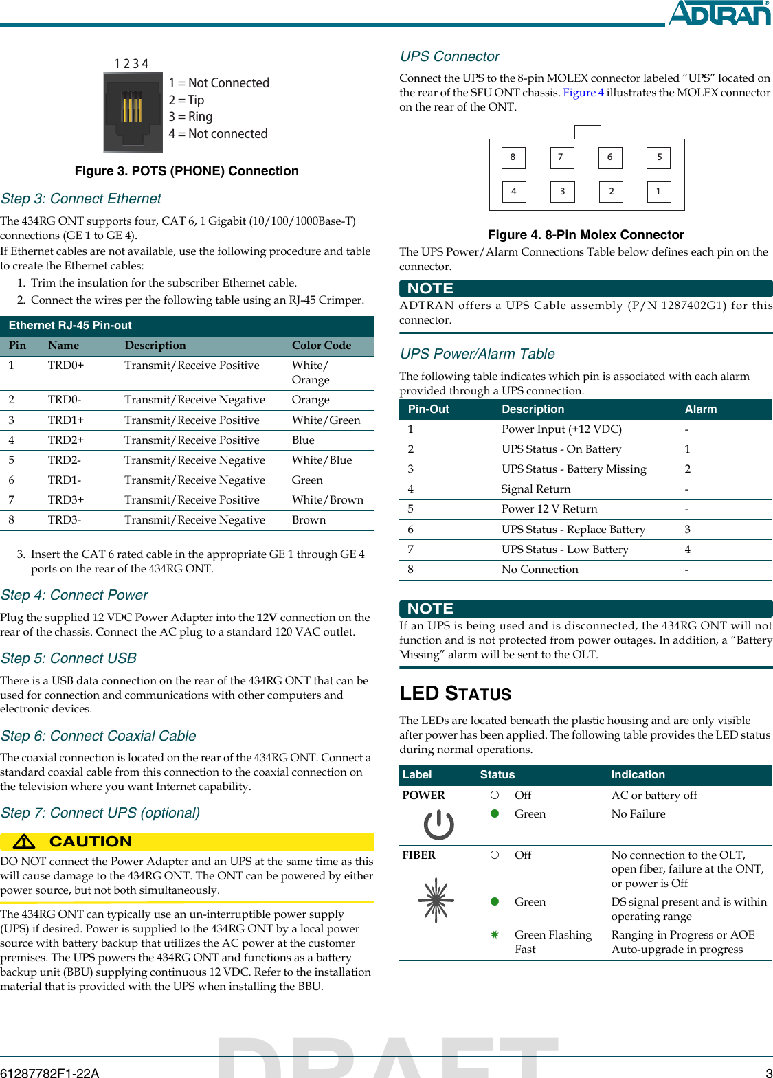
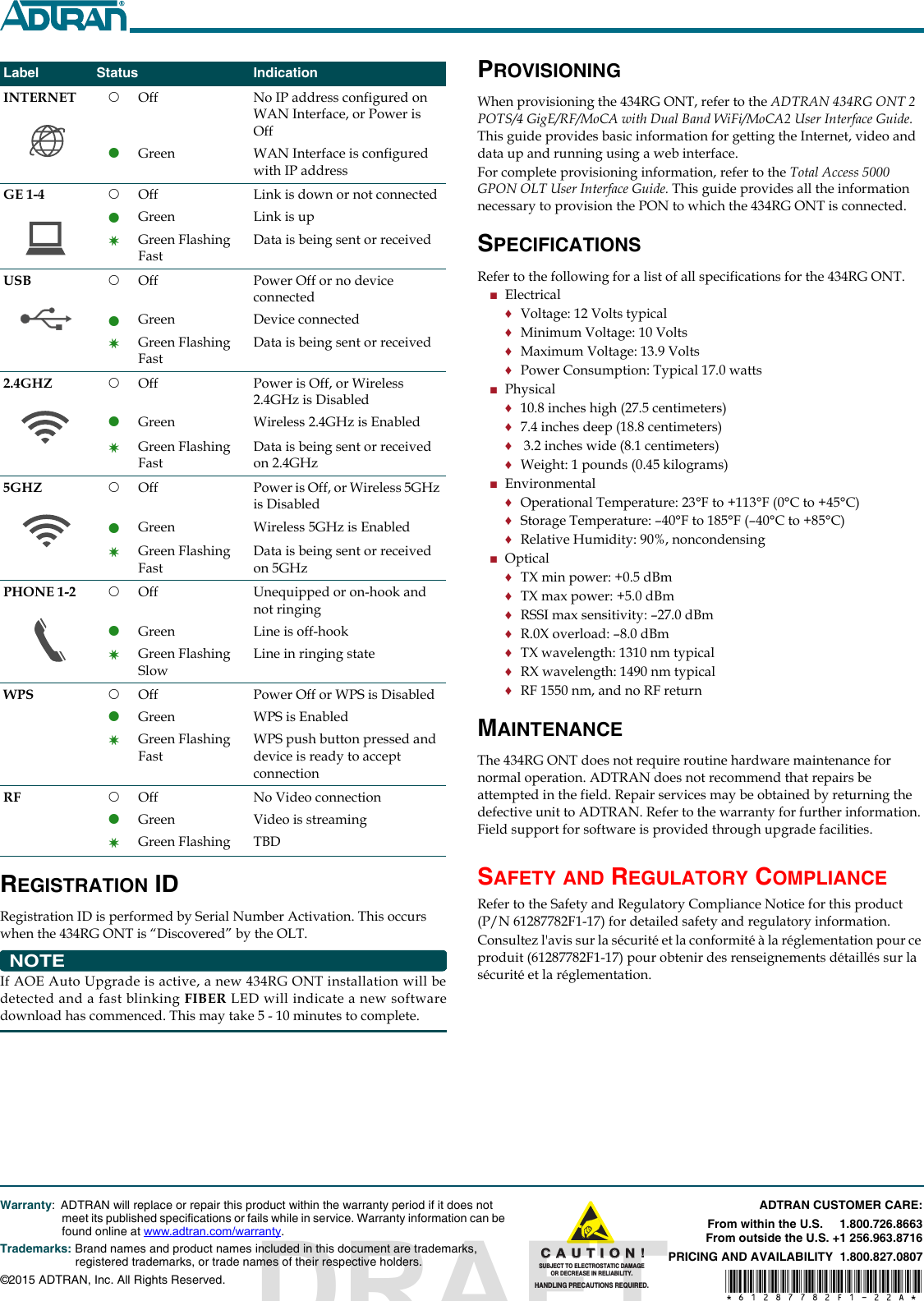
ADTRAN 434RG Indoor GPON HGU User Manual

Adtran Indoor GPON HGU

Contents

Users Manual

jobAid 1DESCRIPTIONThe ADTRAN 434RG 2POTS/4GigE Indoor ONT with RF (434RG ONT, P/N 1287782F1) provides Triple Play and WiFi services to a customer premises. The 434RG ONT also supports RF and Multimedia over Coax Alliance (MoCA 2) with backward compatibility to 1.1. The illustration at the left displays the front and rear of the 434RG ONT. FEATURESThe 434RG ONT supports the following features:■Two POTS (PHONE) Ports■Four Ethernet Ports■2.4 GHz and 5 GHz WiFi■CATV (with Coaxial Connection)■MoCA 2.0 (backward compatible with 1.1)■USB 2.0 Port■12 VDC Power Adapter■UPS Connector■Reset ButtonResetting the ONTA reset button is available if the 434RG ONT needs to be rebooted. The Reset button is located just above the USB port on the rear of the 434RG ONT. To reset the 434RG ONT, press the RESET button for 5 seconds or longer. WARNING!All settings will return to Factory Defaults; registration provisioning will be lost.Voice ProcessingPOTS uses in-band signaling tones and currents to determine call status (for example, call request). Because POTS allows for the transfer of audio signals below 3.3 kHz, POTS systems are also used for modems that allow data transmission (referred to as dial up connections). Ethernet InterfaceThe 434RG ONT supports data service through four 10/100/1000Base-T Ethernet interfaces via RJ-45-style connectors. PowerPower is provided by a 12 VDC Power Adapter that is included with the 434RG ONT. The Power Adapter operates from a main power source input of 100 to 240 VAC, 50/60 Hz, with a nominal output of 12 VDC. The total power consumption with WiFi enabled, 4 Ethernet Ports running and both POTS lines off-hook is approximately 15.0 Watts. A connection for an optional un-interruptible power supply (UPS) is also provided.UPSThe 434RG ONT provides an optional connection for an UPS. An UPS is a battery backup system designed to continue providing power when the primary power source is lost. Power is supplied to the 434RG ONT by a local power source with battery backup that utilizes the AC power at the customer premises and keeps the battery charged.WiFiThe 434RG ONT provides 802.11 a/b/g/n/ac compliant WiFi that support both 2.4 GHz and 5.0 GHz.CLEI: BVMDV00D_ _Product P/N: 1287782F1Issue Date: December 2015Document P/N: 61287782F1-22ADocumentation for ADTRAN® Carrier Networks products is available for viewing and download directly from the ADTRAN Support Community website. Go to: https://supportforums.adtran.com/welcomeRegistration is required.ADTRAN offers training courses on our products, including customized training and courses taught at our facilities or at customer sites.For inquiries, go to: http://adtran.com/trainingThe following related online documents and resources provide additional information for this product:Total Access 5000 GPON OLT User Interface GuideTotal Access 5000 Series CLI DictionaryTotal Access 5000/5006 Engineering GuideTotal Access 5000 Series Fiber to the Premises Deployment GuideADTRAN 434RG ONT 2 POTS/4 GigE/RF/MoCA with Dual Band WiFi User Interface GuideADTRAN 434RG2 POTS/4 GigE/RF/MoCAwith Dual Band WiFiUPSPHONE 1PHONE 2USBRESETGE 1GE 2GE 3GE 412V12RF2.4 5.01234WPSUPSPHONE 2DRAFT
261287782F1-22A3. Thread the fiber cable through the opening in the base. If there is excess fiber, carefully wrap it around the Fiber Tray.4. Remove the dust cover plug from the SC/APC Connector and insert the fiber cable. Retain the dust cover and insert it in the fiber connection when the fiber cable is not connected. This will protect the optical portion of the connection.5. Figure 2 illustrates the 434RG ONT after the base has been attached.Figure 1. Attach 434RG ONT to Base and Connect FiberFigure 2. 434RG ONT with Base AttachedStep 2: Connect POTS (PHONE)If POTS cables are not available, use Figure 3 and the following procedure to create the POTS cables:1. Trim the insulation for the subscriber POTS cables.2. Refer to Figure 3 and connect the twisted-pair Tip (green) and Ring (Red) to the RJ-11 connector using an RJ-11 crimper.3. Insert the RJ-11 connector in the appropriate PHONE 1 or PHONE 2 jack.ScrewFiberTraySC/APCConnectorFiberOpening122.4 5.01234WPSRFCATVCable Television (CATV) is television service that provides cable Internet service with television to customers over the same links - normally coaxial cable. CATV operates at a frequency of 54-870 MHz.MoCA 2.0Multimedia over Coax Alliance (MoCA) is an industry standard technology for connecting the home to a service provider. MoCA technology uses existing coaxial cabling for distributing high definition video with multi-room applications such as DVRs.The 434RG ONT supports MoCA Version 2.0 and is backward compatible to MoCA Version 1.1. MoCA 2.0 operates in C4 and D bands with a frequency range from 1125 to 1500 MHz. Channel bandwidth throughput increased from > 140 Mb/s (MoCA 1.1) to 400 Mb/s. MoCA 2.0.INSTALLATIONAfter unpacking the 434RG ONT, inspect it for damage. If damage is noted, file a claim with the carrier and then contact ADTRAN. For more information, refer to the warranty.Installation consists of positioning the 434RG ONT on a desktop and connecting POTS (PHONE), Ethernet, Fiber, and Power.Installation GuidelinesThe following are guidelines for this installation.■Read all warnings and cautions before installing or servicing the 434RG ONT.■Do not locate the 434RG ONT in direct sunlight or next to any thermal devices.Installation OverviewTo install the 434RG ONT, you will need to complete the following steps:■“Step 1: Attach the 434RG ONT to the Base and connect Fiber”■“Step 2: Connect POTS (PHONE)”■“Step 3: Connect Ethernet”■“Step 4: Connect Power”■“Step 5: Connect USB”■“Step 6: Connect Coaxial Cable”■“Step 7: Connect UPS (optional)”Required toolsStandard technician tools and those listed below are required for installing the 434RG ONT.■PON power meter with wavelength filtering■Fiberscope or videoscopeFor fiber optic connections, the following is required:■ODC Fiber cleaning toolInstallation StepsNOTICEThe 434RG ONT must sit upright using the stand provided. DO NOTlay the ONT flat as it may overheat.Step 1: Attach the 434RG ONT to the Base and connect FiberEnsure the 434RG ONT is not located in direct sunlight and is not located next to any thermal obstructions. To attach the 434RG ONT to the base, refer to Figure 1 and complete the following steps:1. Position the 434RG ONT on the base.2. Using the screw provided, secure the base to the 434RG ONT.DRAFT
61287782F1-22A 3Figure 3. POTS (PHONE) ConnectionStep 3: Connect Ethernet The 434RG ONT supports four, CAT 6, 1 Gigabit (10/100/1000Base-T) connections (GE 1 to GE 4). If Ethernet cables are not available, use the following procedure and table to create the Ethernet cables:1. Trim the insulation for the subscriber Ethernet cable.2. Connect the wires per the following table using an RJ-45 Crimper.3. Insert the CAT 6 rated cable in the appropriate GE 1 through GE 4 ports on the rear of the 434RG ONT.Step 4: Connect PowerPlug the supplied 12 VDC Power Adapter into the 12V connection on the rear of the chassis. Connect the AC plug to a standard 120 VAC outlet.Step 5: Connect USBThere is a USB data connection on the rear of the 434RG ONT that can be used for connection and communications with other computers and electronic devices.Step 6: Connect Coaxial CableThe coaxial connection is located on the rear of the 434RG ONT. Connect a standard coaxial cable from this connection to the coaxial connection on the television where you want Internet capability.Step 7: Connect UPS (optional)CAUTION!DO NOT connect the Power Adapter and an UPS at the same time as thiswill cause damage to the 434RG ONT. The ONT can be powered by eitherpower source, but not both simultaneously.The 434RG ONT can typically use an un-interruptible power supply (UPS) if desired. Power is supplied to the 434RG ONT by a local power source with battery backup that utilizes the AC power at the customer premises. The UPS powers the 434RG ONT and functions as a battery backup unit (BBU) supplying continuous 12 VDC. Refer to the installation material that is provided with the UPS when installing the BBU.Ethernet RJ-45 Pin-outPin Name Description Color Code1 TRD0+ Transmit/Receive Positive White/Orange2 TRD0- Transmit/Receive Negative Orange3 TRD1+ Transmit/Receive Positive White/Green4 TRD2+ Transmit/Receive Positive Blue5 TRD2- Transmit/Receive Negative White/Blue6 TRD1- Transmit/Receive Negative Green7 TRD3+ Transmit/Receive Positive White/Brown8 TRD3- Transmit/Receive Negative Brown1 2 3 41 = Not Connected2 = Tip3 = Ring4 = Not connectedUPS ConnectorConnect the UPS to the 8-pin MOLEX connector labeled “UPS” located on the rear of the SFU ONT chassis. Figure 4 illustrates the MOLEX connector on the rear of the ONT.Figure 4. 8-Pin Molex ConnectorThe UPS Power/Alarm Connections Table below defines each pin on the connector. NOTEADTRAN offers a UPS Cable assembly (P/N 1287402G1) for thisconnector.UPS Power/Alarm TableThe following table indicates which pin is associated with each alarm provided through a UPS connection.NOTEIf an UPS is being used and is disconnected, the 434RG ONT will notfunction and is not protected from power outages. In addition, a “BatteryMissing” alarm will be sent to the OLT.LED STATUSThe LEDs are located beneath the plastic housing and are only visible after power has been applied. The following table provides the LED status during normal operations.Pin-Out Description Alarm1 Power Input (+12 VDC) -2UPS Status - On Battery13 UPS Status - Battery Missing 24 Signal Return - 5Power 12 V Return-6 UPS Status - Replace Battery 37 UPS Status - Low Battery 48 No Connection  - Label Status IndicationPOWER OffGreenAC or battery offNo FailureFIBER 2OffGreenGreen Flashing FastNo connection to the OLT, open fiber, failure at the ONT, or power is OffDS signal present and is within operating rangeRanging in Progress or AOE Auto-upgrade in progress87 6 5434321DRAFT
C A U T I O N C A U T I O N ! SUBJECT TO ELECTROSTATIC DAMAGEOR DECREASE IN RELIABILITY.HANDLING PRECAUTIONS REQUIRED.Warranty: ADTRAN will replace or repair this product within the warranty period if it does not meet its published specifications or fails while in service. Warranty information can be found online at www.adtran.com/warranty.Trademarks: Brand names and product names included in this document are trademarks,    registered trademarks, or trade names of their respective holders.©2015 ADTRAN, Inc. All Rights Reserved.ADTRAN CUSTOMER CARE:From within the U.S.     1.800.726.8663From outside the U.S. +1 256.963.8716PRICING AND AVAILABILITY  1.800.827.0807*61287782F1-22A*REGISTRATION IDRegistration ID is performed by Serial Number Activation. This occurs when the 434RG ONT is “Discovered” by the OLT.NOTEIf AOE Auto Upgrade is active, a new 434RG ONT installation will bedetected and a fast blinking FIBER LED will indicate a new softwaredownload has commenced. This may take 5 - 10 minutes to complete.INTERNET OffGreenNo IP address configured on WAN Interface, or Power is OffWAN Interface is configured with IP addressGE 1-4 2OffGreenGreen Flashing FastLink is down or not connectedLink is upData is being sent or receivedUSB 2OffGreenGreen Flashing FastPower Off or no device connectedDevice connectedData is being sent or received2.4GHZ 2OffGreenGreen Flashing FastPower is Off, or Wireless 2.4GHz is DisabledWireless 2.4GHz is EnabledData is being sent or received on 2.4GHz5GHZ 2OffGreenGreen Flashing FastPower is Off, or Wireless 5GHz is DisabledWireless 5GHz is EnabledData is being sent or received on 5GHzPHONE 1-2 2OffGreenGreen Flashing SlowUnequipped or on-hook and not ringingLine is off-hookLine in ringing stateWPS 2OffGreenGreen Flashing FastPower Off or WPS is DisabledWPS is EnabledWPS push button pressed and device is ready to accept connectionRF 2OffGreenGreen Flashing No Video connectionVideo is streamingTBDLabel Status Indication PROVISIONINGWhen provisioning the 434RG ONT, refer to the ADTRAN 434RG ONT 2 POTS/4 GigE/RF/MoCA with Dual Band WiFi/MoCA2 User Interface Guide. This guide provides basic information for getting the Internet, video and data up and running using a web interface.For complete provisioning information, refer to the Total Access 5000 GPON OLT User Interface Guide. This guide provides all the information necessary to provision the PON to which the 434RG ONT is connected.SPECIFICATIONSRefer to the following for a list of all specifications for the 434RG ONT.■Electrical♦Voltage: 12 Volts typical♦Minimum Voltage: 10 Volts♦Maximum Voltage: 13.9 Volts♦Power Consumption: Typical 17.0 watts■Physical♦10.8 inches high (27.5 centimeters)♦7.4 inches deep (18.8 centimeters)♦ 3.2 inches wide (8.1 centimeters)♦Weight: 1 pounds (0.45 kilograms)■Environmental♦Operational Temperature: 23°F to +113°F (0°C to +45°C)♦Storage Temperature: –40°F to 185°F (–40°C to +85°C)♦Relative Humidity: 90%, noncondensing■Optical♦TX min power: +0.5 dBm♦TX max power: +5.0 dBm♦RSSI max sensitivity: –27.0 dBm♦R.0X overload: –8.0 dBm♦TX wavelength: 1310 nm typical♦RX wavelength: 1490 nm typical♦RF 1550 nm, and no RF returnMAINTENANCEThe 434RG ONT does not require routine hardware maintenance for normal operation. ADTRAN does not recommend that repairs be attempted in the field. Repair services may be obtained by returning the defective unit to ADTRAN. Refer to the warranty for further information. Field support for software is provided through upgrade facilities.SAFETY AND REGULATORY COMPLIANCERefer to the Safety and Regulatory Compliance Notice for this product (P/N 61287782F1-17) for detailed safety and regulatory information.Consultez l'avis sur la sécurité et la conformité à la réglementation pour ce produit (61287782F1-17) pour obtenir des renseignements détaillés sur la sécurité et la réglementation.DRAFT

Navigation menu