Advance Multimedia Internet Technology CDW531AM WiFi Combo/Broadband Gateway User Manual CDW531AM User Guide
Advance Multimedia Internet Technology Inc. WiFi Combo/Broadband Gateway CDW531AM User Guide
UserManual.wiki
>
Advance Multimedia Internet Technology
>
CDW531AM User Manual
Manual
Navigation menu
Upload a User Manual
Namespaces
Wiki Guide
HTML
PDF
Info
Views
User Manual
Discussion / Help
Navigation
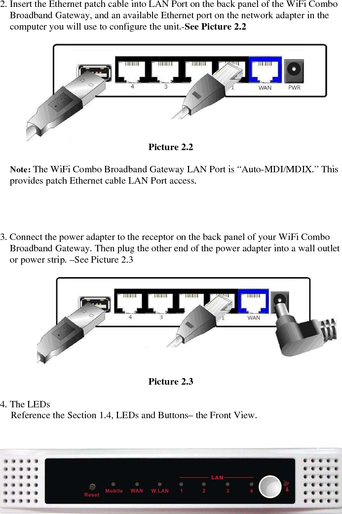
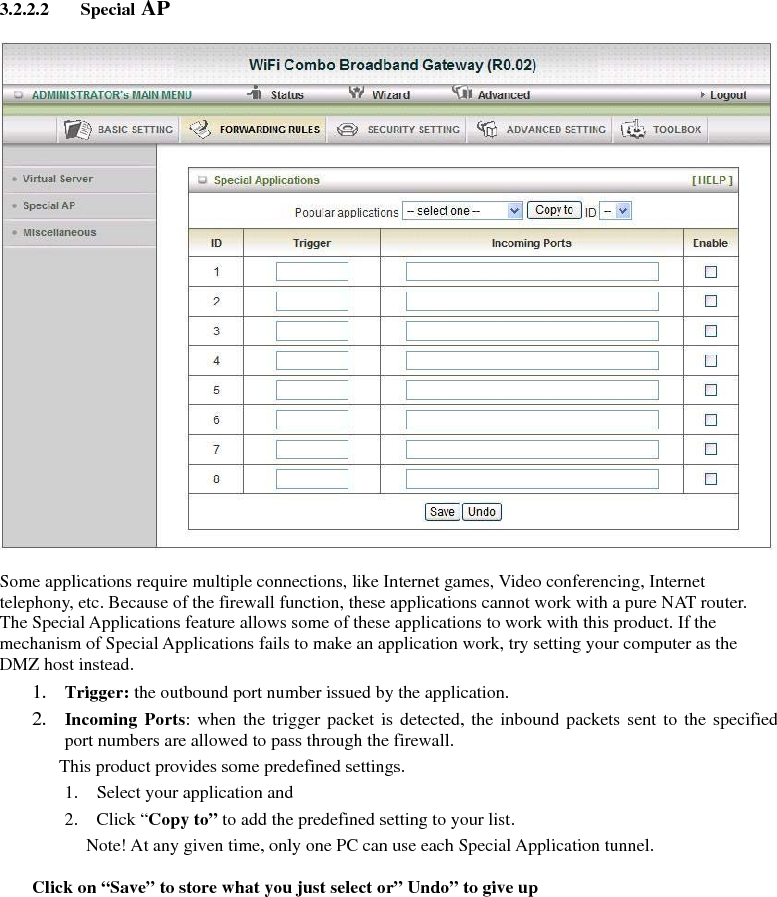
![2. Configuring WiFi Combo Broadband Gateway 2.1. Installation Considerations The WiFi Combo Broadband Gateway allows you access your network using a wireless connection, from virtually anywhere within its operating range. Keep in mind however, that the number, thickness, and location of walls, ceilings, or other objects that the wireless signals must pass through, may limit this range. Typical ranges vary depending on the types of materials used, and background RF (radio frequency) noise in your home or business. To maximize your wireless range, please follow these guidelines: 1. Keep the number of walls and ceilings between the WiFi Combo Broadband Gateway and other network devices to a minimum. Each wall or ceiling can reduce the WiFi Combo Broadband Gateway’s range from 3-90 feet (1-30 meters). Note: The same considerations apply to your broadband EVDO connection. 2. Keep your product aware from electrical devices (such as microwaves, air conditioners, and televisions) that emit large quantities of RFI (Radio Frequency Interference). 2.1.1. Installation Instructions- Get Start Networking Connect this Gateway to Your Network Note: DO NOT connect WiFi Combo Broadband Gateway to power before performing the installation steps below. 1. Connect a USB modem with service to the WiFi Combo Broadband Gateway-- See Picture 2.1 Picture 2.1 Note: The WiFi Combo Broadband Gateway is designed to work with either UMTS or EV-DO and even HSDPA 3G cards that can be used as a modem (support tethered data). Please refer to your service provider for detailed feature information. 註解 [01]: 加上 to allow you to 註解 [02]: 應改為 However,keep in mind that 註解 [03]: 應改為 away](https://usermanual.wiki/Advance-Multimedia-Internet-Technology/CDW531AM/User-Guide-1227874-Page-7.png)
![2.1.2. Establish WiFi Connection If you selected either WEP or WPA-PSK encryption, ensure these settings match your WiFi adapter settings. WiFi and encryption settings must match for access to the WiFi Combo Broadband Gateway Configuration Menu, and the Internet. Please refer to your WiFi adapter documentation for additional information. 註解 [04]: 刪除 for](https://usermanual.wiki/Advance-Multimedia-Internet-Technology/CDW531AM/User-Guide-1227874-Page-9.png)
![Step 2: Allow you to change the Time Zone. You can change Time Zone here. Or you can click the button “Detect Again”, the Time Zone will be changed to same with your PC. Step 3: Select WAN Types will be used for Internet connection Step3-1: Auto Detecting & Manually Setting WAN Type 1. Reference Section 2.1 Installation Considerations to setup the environment 2. We are support the Dynamic & PPPOE WAN Type for Auto Detecting. Click on “Next” button 註解 [05]: 刪除 will be 註解 [06]: 刪除 are](https://usermanual.wiki/Advance-Multimedia-Internet-Technology/CDW531AM/User-Guide-1227874-Page-14.png)
![Step3-2: Select WAN Type Pick up one of types you preferred to. Click on “Next” button You can select the Static, Dynamic, PPPOE, PPTP, L2TP and 3G WAN Types. We show you How to setup the 3G WAN Type only. Reference the Section 3.2.1.1 Primary Setup for more information Step 3-3: Setup the 3G WAN will be used for Internet connection. 1. LAN IP Address: The IP address of the LAN interface. The default IP address is: 192.168.123.254 2. Enter the 3G Modem Card information by your 3G broadband service provider. Click on “Next” button 註解 [07]: 加上 the The types](https://usermanual.wiki/Advance-Multimedia-Internet-Technology/CDW531AM/User-Guide-1227874-Page-15.png)
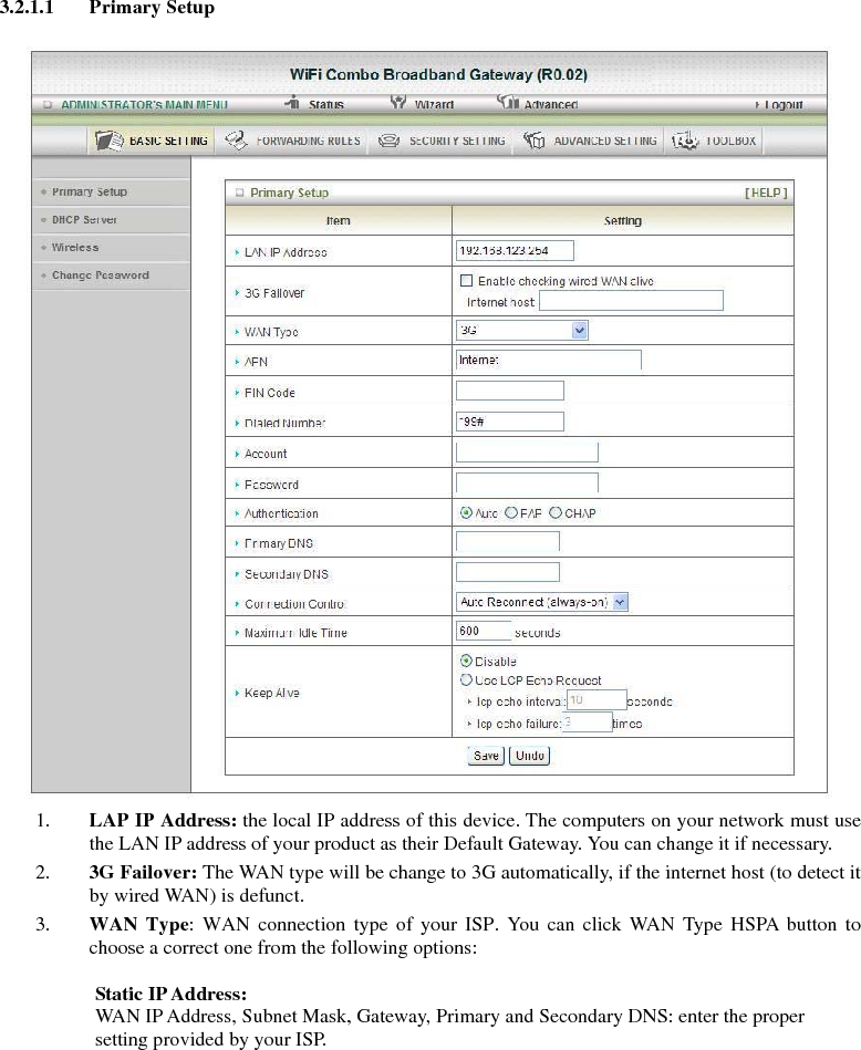
![3G For 3G WAN Networking. The WAN fields may not be necessary for your connection. The information on this page will only be used when your service provider requires you to enter a User Name and Password to connect to the 3G network. Please refer to your documentation or service provider for additional information. 1. APN: Enter the APN for your PC card here. 2. Pin Code: Enter the Pin Code for your SIM card 3. Dial-Number: This field should not be altered except when required by your service provider. 4. User Name: Enter the new User Name for your PC card here. 5. Password: Enter the new Password for your PC card here. 6. Primary DNS: This feature allows you to assign a Primary DNS Server(Optional) 7. Secondary DNS: This feature allows you to assign a Secondary DNS Server(Optional) 8. Connection Control: There are 3 modes to select: Connect on Demand: The device will link up with ISP when the clients send outgoing packets. Auto Reconnect (always-on): The device will link with ISP until the connection is established. Manually: The device will not make the link until someone clicks the connect-button in the Status-page. 9. Maximum Idle Time: The Connection will be broken when the idle time arrives. 10. Keep Alive: There are 2 modes to select: Disable / Use LCP Echo Request. 註解 [08]: For…, the WAN….](https://usermanual.wiki/Advance-Multimedia-Internet-Technology/CDW531AM/User-Guide-1227874-Page-23.png)
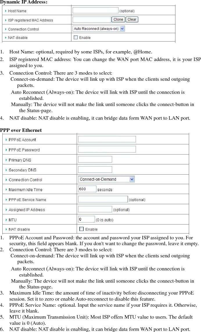
![3.2.1.2 DHCP Server 1. Press “More>>”, for more settings. 2. DHCP Server: Choose either Disable or Enable. 3. IP Pool Starting/Ending Address: Whenever there is a request, the DHCP server will automatically allocate an unused IP address from the IP address pool to the requesting computer. You must specify the starting / ending address of the IP address pool. 4. Lease Time: DHCP lease time to the DHCP client. 5. Domain Name: Optional, this information will be passed to the client 6. Primary DNS/Secondary DNS: Optional, This feature allows you to assign a DNS Servers 7. Primary WINS/Secondary WINS: Optional, this feature allows you to assign a WINS Servers 8. Gateway: Optional, Gateway Address would be the IP address of an alternate Gateway. This function enables you to assign another gateway to your PC, when DHCP server offers an IP to your PC. 9. Clients List...: Reference the next Page “DHCP Clients List”. 10. Fixed Mapping...: Reference the next page “DHCP Fixed Mapping”. After you finish your selection then Either Click on “Save” to store what you just pick or click “Undo” to give up 註解 [09]: 應改為 Press… for more…. 註解 [010]: 應該為 Refer to……. 註解 [011]: 應該為 Refer to…. 註解 [012]: 應該為 After…, then……](https://usermanual.wiki/Advance-Multimedia-Internet-Technology/CDW531AM/User-Guide-1227874-Page-24.png)
![DHCP Clients List Delete: The selected items will be deleted. Fixed Mapping: The selected items will be added to the Fix Mapping Table. DHCP Fixed Mapping The DHCP server will reserve the IP address for the Client, which have the MAC address. 註解 [013]: 應該為 has](https://usermanual.wiki/Advance-Multimedia-Internet-Technology/CDW531AM/User-Guide-1227874-Page-25.png)
![Open Open system authentication simply consists of two communications. The first is an authentication request by the client that contains the station ID (typically the MAC address). This is followed by an authentication response from the AP/gateway containing a success or failure message. An example of when a failure may occur is if the client's MAC address is explicitly excluded in the AP/gateway configuration. Shared Shared key authentication relies on the fact that both stations taking part in the authentication process have the same "shared" key or passphrase. The shared key is manually set on both the client station and the AP/gateway. Three types of shared key authentication are available today for home or small office WLAN environments. Auto The AP will Select the Open or Shared by the client’s request automatically. WPA-PSK Select Encryption and Pre-share Key Mode If you select HEX, you have to fill in 64 hexadecimal (0, 1, 2…8, 9, A, B…F) digits. If you select ASCII, the length of pre-share key is from 8 to 63. Fill in the key, Ex 12345678 WPA Check Box was used to switch the function of the WPA. When the WPA function is enabled, the Wireless user must authenticate to this gateway first to use the Network service. RADIUS Server IP address or the 802.1X server’s domain-name. Select Encryption and RADIUS Shared Key If you select HEX, you have to fill in 64 hexadecimal (0, 1, 2…8, 9, A, B…F) digits If you select ASCII, the length of pre-share key is from 8 to 63. Key value shared by the RADIUS server and this gateway. This key value is consistent with the key value in the RADIUS server. WPA-PSK2 WPA-PSK2 user AES and TKIP for Same the encryption, the others are same the WPA-PSK. WPA2 WPA2 add uses AES and TKIP for encryption, the others are same the WPA. WPA-PSK/WPA-PSK2 Another encryption options for WPA-PSK-TKIP and WPA-PSK2-AES, the others are same the WPA-PSK. WPA/WPA2 Another encryption options for WPA-TKIP and WPA2-AES, the others are same the WPA. 註解 [014]: 應改為 are same with 註解 [015]: 應改為 are same with 註解 [016]: 應改為 are same with](https://usermanual.wiki/Advance-Multimedia-Internet-Technology/CDW531AM/User-Guide-1227874-Page-27.png)
![Wireless Client List The list of wireless client is shows here. 3.2.1.4 Change Password You can change Password here. We strongly recommend you to change the system password for security reason. Click on “Save” to store what you just select or “Undo” to give up 註解 [017]: 應改為 shown](https://usermanual.wiki/Advance-Multimedia-Internet-Technology/CDW531AM/User-Guide-1227874-Page-29.png)
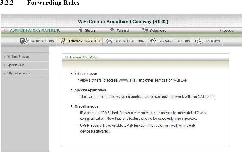
![3.2.2.1 Virtual Server This product’s NAT firewall filters out unrecognized packets to protect your Intranet, so all hosts behind this product are invisible to the outside world. If you wish, you can make some of them accessible by enabling the Virtual Server Mapping. A virtual server is defined as a Service Port, and all requests to this port will be redirected to the computer specified by the Server IP. Virtual Server can work with Scheduling Rules, and give user more flexibility on Access control. For Detail, please refer to Scheduling Rule. For example, if you have an FTP server (port 21) at 192.168.123.1 and Scheduling Rule(0), a Web server (port 80) at 192.168.123.2 and Scheduling Rule(1), a VPN server at 192.168.123.6 and Scheduling Rule(2), then you need to specify the following virtual server mapping table: 註解 [018]: 字尾加上 s](https://usermanual.wiki/Advance-Multimedia-Internet-Technology/CDW531AM/User-Guide-1227874-Page-31.png)

![3.2.2.3 Miscellaneous 1. IP Address of DMZ Host DMZ (Demilitarized Zone) Host is a host without the protection of firewall. It allows a computer to be exposed to unrestricted 2-way communication for Internet games, Video conferencing, Internet telephony and other special applications. 2. UPnP Setting The device also supports this function. If the OS supports this function enable it, like Windows XP. When the user gets IP from Device and will see icon as below: Click on “Save” to store what you just select or “Undo” to give up 註解 [019]: 刪除 and 改為…., they](https://usermanual.wiki/Advance-Multimedia-Internet-Technology/CDW531AM/User-Guide-1227874-Page-34.png)
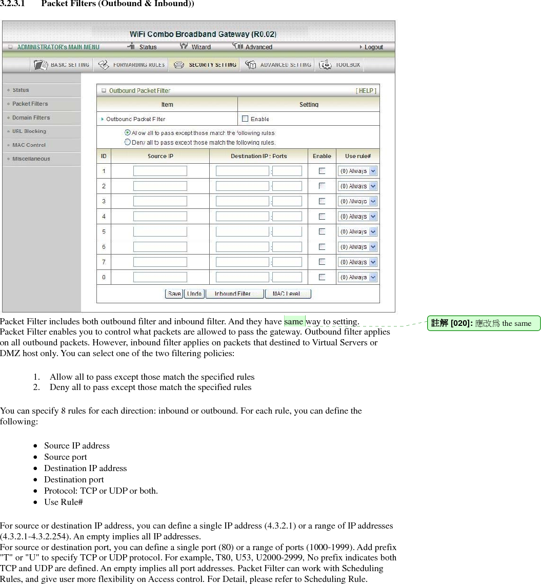
![3.2.3.1 Packet Filters (Outbound & Inbound)) Packet Filter includes both outbound filter and inbound filter. And they have same way to setting. Packet Filter enables you to control what packets are allowed to pass the gateway. Outbound filter applies on all outbound packets. However, inbound filter applies on packets that destined to Virtual Servers or DMZ host only. You can select one of the two filtering policies: 1. Allow all to pass except those match the specified rules 2. Deny all to pass except those match the specified rules You can specify 8 rules for each direction: inbound or outbound. For each rule, you can define the following: • Source IP address • Source port • Destination IP address • Destination port • Protocol: TCP or UDP or both. • Use Rule# For source or destination IP address, you can define a single IP address (4.3.2.1) or a range of IP addresses (4.3.2.1-4.3.2.254). An empty implies all IP addresses. For source or destination port, you can define a single port (80) or a range of ports (1000-1999). Add prefix "T" or "U" to specify TCP or UDP protocol. For example, T80, U53, U2000-2999, No prefix indicates both TCP and UDP are defined. An empty implies all port addresses. Packet Filter can work with Scheduling Rules, and give user more flexibility on Access control. For Detail, please refer to Scheduling Rule. 註解 [020]: 應改為 the same](https://usermanual.wiki/Advance-Multimedia-Internet-Technology/CDW531AM/User-Guide-1227874-Page-36.png)
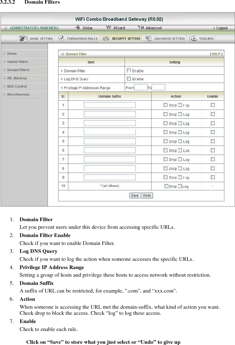
![3.2.3.3 URL Blocking URL Blocking will block LAN computers to connect to pre-define Websites. The major difference between “Domain filter” and “URL Blocking” is Domain filter require user to input suffix (like .com or .org, etc), while URL Blocking require user to input a keyword only. In other words, Domain filter can block specific website, while URL Blocking can block hundreds of websites by simply a keyword. 1. URL Blocking Enable Check if you want to enable URL Blocking. 2. URL If any part of the Website's URL matches the pre-defined word, the connection will be blocked. For example, you can use pre-defined word "sex" to block all websites if their URLs contain pre-defined word "sex". 3. Enable Check to enable each rule. Click on “Save” to store what you just select or “Undo” to give up 註解 [021]: 字尾加上 s 註解 [022]: 刪除 s](https://usermanual.wiki/Advance-Multimedia-Internet-Technology/CDW531AM/User-Guide-1227874-Page-39.png)
![3.2.3.4 MAC Control MAC Address Control allows you to assign different access right for different users and to assign a specific IP address to a certain MAC address. 1. MAC Address Control Check “Enable” to enable the “MAC Address Control”. All of the settings in this page will take effect only when “Enable” is checked. 2. Connection control Check "Connection control" to enable the controlling of which wired and wireless clients can connect to this device. If a client is denied to connect to this device, it means the client can't access to the Internet either. Choose "allow" or "deny" to allow or deny the clients, whose MAC addresses are not in the "Control table" (please see below), to connect to this device. 3. Association control Check "Association control" to enable the controlling of which wireless client can associate to the wireless LAN. If a client is denied to associate to the wireless LAN, it means the client can't send or receive any data via this device. Choose "allow" or "deny" to allow or deny the clients, whose MAC addresses are not in the "Control table", to associate to the wireless LAN Click on “Save” to store what you just select or “Undo” to give up Click on “Next Page” to go down or “Previous page” back to last page 註解 [023]: 刪除逗點且應該為小寫 choose 註解 [024]: 應改為controllable](https://usermanual.wiki/Advance-Multimedia-Internet-Technology/CDW531AM/User-Guide-1227874-Page-40.png)
![3.2.3.5 Miscellaneous 1. Administrator Time-out The time of no activity to logout automatically, you may set it to zero to disable this feature. 2. Remote Administrator Host/Port In general, only Intranet user can browse the built-in web pages to perform administration task. This feature enables you to perform administration task from remote host. If this feature is enabled, only the specified IP address can perform remote administration. If the specified IP address is 0.0.0.0, any host can connect to this product to perform administration task. You can use subnet mask bits "/nn" notation to specified a group of trusted IP addresses for example, "10.1.2.0/24". NOTE: When Remote Administration is enabled, the web server port will be shifted to 80. You can change web server port to other port, too. 3. Discard PING from WAN side When this feature is enabled, any host on the WAN cannot ping this product. 4. DoS Attack Detection When this feature is enabled, the gateway will detect and log the DoS attack comes from the Internet. Currently, the gateway can detect the following DoS attack: SYN Attack, Win Nuke, Port Scan, Ping of Death, Land Attack etc. Click on “Save” to store what you just select or” Undo” to give up 註解 [025]: 應改為 coming](https://usermanual.wiki/Advance-Multimedia-Internet-Technology/CDW531AM/User-Guide-1227874-Page-41.png)
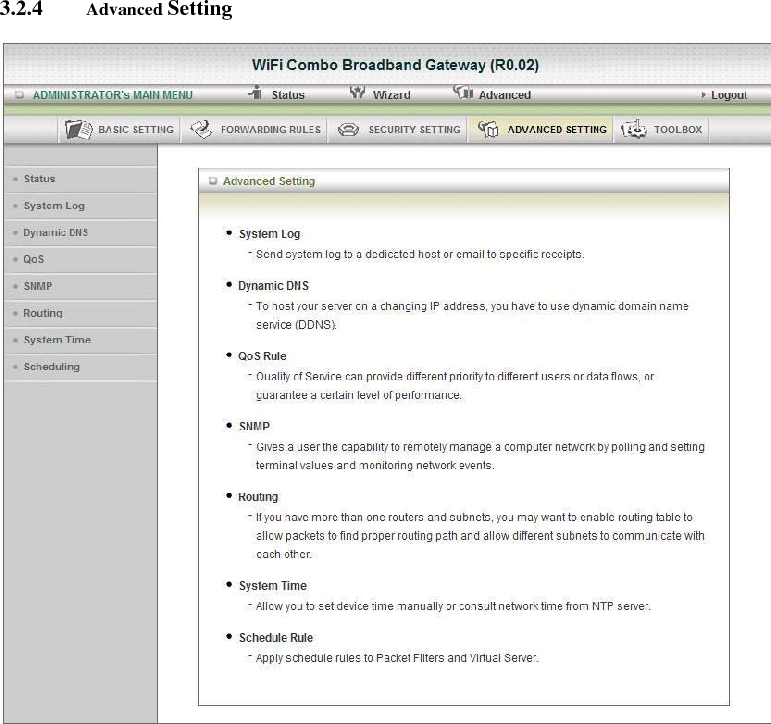
![3.2.4.1 System Log This page supports two methods to export system logs to specific destination by means of syslog (UDP) and SMTP (TCP). The items you have to setup including: 1. IP Address for Syslog Host IP of destination where syslog will be sent to. Check Enable to enable this function. 2. E-mail Alert Enable Check if you want to enable Email alert (send syslog via email). A. SMTP Server IP and Port Input the SMTP server IP and port, which are concated with ':'. If you do not specify port number, the default value is 25. For example, "mail.your_url.com" or "192.168.1.100:26". B. SMTP Username/Password The username and password login the SMTP server. C. E-mail address The recipients who will receive these logs, you can assign more than 1 recipient, using ';' or ',' to separate these email addresses. D. E-mail Subject The subject of email alert, this setting is optional. 3. View Log...: Reference the Section 3.2.5.1 System Info. Click on “Save” to store what you just select or “Undo” to give up 註解 [026]: 應改為 註解 [027]: 應改為](https://usermanual.wiki/Advance-Multimedia-Internet-Technology/CDW531AM/User-Guide-1227874-Page-43.png)
![3.2.4.2 Dynamic DNS To host your server on a changing IP address, you have to use dynamic domain name service (DDNS). So that anyone wishing to reach your host only needs to know the name of it. Dynamic DNS will map the name of your host to your current IP address, which changes each time you connect your Internet service provider. Before you enable Dynamic DNS, you need to register an account on one of these Dynamic DNS servers that we list in provider field. To enable Dynamic DNS click the check box next to Enable in the DDNS field. Next you can enter the appropriate information about your Dynamic DNS Server. You have to define: Provider Host Name Username/E-mail Password/Key You will get this information when you register an account on a Dynamic DNS server. Click on “Save” to store what you just select or “Undo” to give up 註解 [028]: 應改為Therefore,](https://usermanual.wiki/Advance-Multimedia-Internet-Technology/CDW531AM/User-Guide-1227874-Page-44.png)
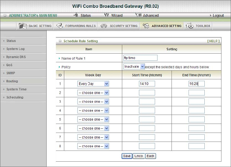
![3.2.4.3 QOS Provide different priority to different users or data flows, or guarantee a certain level of performance. 1. Enable This Item enables QoS function or not. 2. Bandwidth of Upstream Set the limitation of upstream speed. 3. Local: IP Define the Local IP address of packets here. 4. Local: Ports Define the Local port of the packets in this field. 5. Remote: IP Define the Remote IP address of packets here. 6. Remote: Ports Define the Remote port of the packets in this field. 7. QoS Priority This defines the priority level of the current Policy Configuration. Packets associated with this policy will be serviced based upon the priority level set. For critical applications High or Normal levels are recommended. For non-critical applications select a Low level. 8. User Rule# The QoS item can work with Scheduling Rule number#. Please reference the section 4.7.7 schedule. Click on “Save” to store what you just select or “Undo” to give up 註解 [029]: 刪除 註解 [030]: 應改為 refer to](https://usermanual.wiki/Advance-Multimedia-Internet-Technology/CDW531AM/User-Guide-1227874-Page-45.png)
![3.2.4.4 SNMP In brief, SNMP, the Simple Network Management Protocol, is a protocol designed to give a user the capability to remotely manage a computer network by polling and setting terminal values and monitoring network events. 1. Enable SNMP You must check Local, Remote or both to enable SNMP function. If Local is checked, this device will response request from LAN. If Remote is checked, this device will response request from WAN. 2. Get Community Setting the community of Get Request your device will response. 3. Set Community Setting the community of Set Request your device will accept. IP 1, IP 2, IP 3, IP 4 Input your SNMP Management PC’s IP here. User has to configure to where this device should send SNMP Trap message. 4. SNMP Version Please select proper SNMP Version that your SNMP Management software supports. 5. WAN Access IP Address If the user wants to limit to specific the IP address to access, please input in the item. The default 0.0.0.0 and means every IP of Internet can get some information of device with SNMP protocol. Click on “Save” to store what you just select or “Undo” to give up. 註解 [031]: 刪除 and](https://usermanual.wiki/Advance-Multimedia-Internet-Technology/CDW531AM/User-Guide-1227874-Page-46.png)
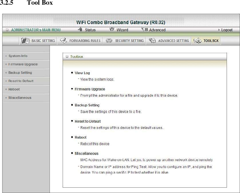
![3.2.5.1 System Info You can view the System Information and System log. And download/clear the System log, in this page. 註解 [032]: 刪除逗號](https://usermanual.wiki/Advance-Multimedia-Internet-Technology/CDW531AM/User-Guide-1227874-Page-52.png)
![3.2.5.2 Firmware Upgrade You can upgrade firmware by clicking “Upgrade” button. 3.2.5.3 Backup Setting You can backup your settings by clicking the “Backup Setting” button and save it as a bin file. Once you want to restore these settings, please reference the Section 3.2.5.2 Firmware Upgrade. 3.2.5.4 Reset to Default You can also reset this product to factory default by clicking the Reset to default button. 3.2.5.5 Reboot You can also reboot this product by clicking the Reboot button. 註解 [033]: 應改為 refer to](https://usermanual.wiki/Advance-Multimedia-Internet-Technology/CDW531AM/User-Guide-1227874-Page-53.png)
![3.2.5.6 Miscellaneous 1. MAC Address for Wake-on-LAN Wake-on-LAN is a technology that enables you to power up a networked device remotely. In order to enjoy this feature, the target device must be Wake-on-LAN enabled and you have to know the MAC address of this device, say 00-11-22-33-44-55. Clicking "Wake up" button will make the gateway to send the wake-up frame to the target device immediately. 2. Domain Name or IP address for Ping Test You can key in URL or IP address, and then click the “Ping” button for test. 註解 [034]: 應改為 saying](https://usermanual.wiki/Advance-Multimedia-Internet-Technology/CDW531AM/User-Guide-1227874-Page-54.png)
![Troubleshooting This section provides an overview of common issues, and possible solutions for the installation and operation of the WiFi Combo Broadband Gateway. 1. Unable to access the Configuration Menu when I use my computer to configure the gateway. Why? Note: It is recommended that you use an Ethernet connection to configure the Ensure that the Ethernet LED on the WiFi Combo Broadband Gateway is ON. If the LED is NOT ON, check to see if the cable for the Ethernet connection is securely inserted. Note: Ensure that the IP Address is in the same range and subnet as the WiFi Combo Broadband Gateway. The IP Address of the WiFi Combo Broadband Gateway is 192.168.123.254. All the computers on the network must have a unique IP Address within the same range (e.g., 192.168.123.x). Any computers that have identical IP Addresses will not be visible on the network. All computers must also have the same subnet mask (e.g., 255.255.255.0). Do a Ping test to make sure that the WiFi Combo Broadband Gateway is responding. Go to Start > Run. 1: Type cmd. 2: Press Enter. 3: Type “ping 192.168.123.254”. A successful ping shows four replies. Note: If you have changed the default IP Address, ensure you ping the correct IP Address assigned to the WiFi Combo Broadband Gateway. Ensure that your Ethernet Adapter is working properly, and that all network drivers are installed properly. Note: Network adapter names will vary depending on your specific adapter. The installation steps listed below are applicable for all network adapters. 1. Go to Start > My Computer > Properties. 2. Select the Hardware Tab. 3. Click Device Manager. 4. Double-click on “Network Adapters”. 5. Right-click on Wireless Card bus Adapter, or your specific network adapter. 6. Select Properties to ensure that all drivers are installed properly. 7. Look under Device Status to see if the device is working properly. 8. Click “OK”. 2: Why my wireless client can NOT access the Internet? Note: Establish WiFi Connection. As long as you select either WEP or WPA-PSK encryption, ensure encryption settings match your WiFi settings. Please refer to your WiFi adapter documentation for additional information. Ensure that the wireless client is associated and joined with the correct Access Point. To check this connection, follow the steps below: 1. Right-click on the Local Area Connection icon in the taskbar. 2. Select View Available Wireless Networks in Wireless Configure. The Connect to Wireless Network screen appears. Ensure you have selected the correct available network. 註解 [035]: 沒有句點](https://usermanual.wiki/Advance-Multimedia-Internet-Technology/CDW531AM/User-Guide-1227874-Page-55.png)
![Ensure the IP Address assigned to the wireless adapter is within the same subnet as the Access Point and gateway. The WiFi Combo Broadband Gateway has an IP Address of 192.168.123.254. Wireless adapters must have an IP Address in the same range (e.g., 192.168.123.x). Although the subnet mask must be the same for all the computers on the network, no two devices may have the same IP Address. Therefore, each device must have a unique IP Address. To check the IP Address assigned to the wireless adapter, follow the steps below: 1. Enter ipconfig /all in command mode 2. Enter ping 192.168.123.254.to check if you can access the WiFi Combo Broadband Gateway. 3. Why does my wireless connection keep dropping? You may try following steps to solve. • Antenna Orientation. 1: Try different antenna orientations for the WiFi Combo Broadband Gateway. 2: Try to keep the antenna at least 6 inches away from the wall or other objects. • Try changing the channel on the WiFi Combo Broadband Gateway, and your Access Point and Wireless adapter to a different channel to avoid interference. • Keep your product away (at least 3-6 feet) from electrical devices that generate RF noise, like microwaves, monitors, electric motors, etc. 4. Why I am unable to achieve a wireless connection? Note: An Ethernet connection is required to troubleshoot the WiFi Combo Broadband Gateway. If you have enabled Encryption on the WiFi Combo Broadband Gateway, you must also enable encryption on all wireless clients in order to establish a wireless connection. • For 802.11g, the encryption settings are: 64 or 128 bit. Ensure that the encryption bit level is the same for both the WiFi Combo Broadband Gateway, and your Wireless Client. • Ensure that the SSID (Service Set Identifier) on the WiFi Combo Broadband Gateway and the Wireless Client are exactly the same. If they are not, your wireless connection will not be established. • Move the WiFi Combo Broadband Gateway and the wireless client into the same room, and then test the wireless connection. • Disable all security settings such as WEP, and MAC Address Control. • Turn off the WiFi Combo Broadband Gateway and the client. Turn the WiFi Combo Broadband Gateway back on again, and then turn on the client. • Ensure that all devices are set to Infrastructure mode. • Ensure that the LED indicators are indicating normal activity. If not, ensure that the AC power and Ethernet cables are firmly connected. • Ensure that the IP Address, subnet mask, gateway and DNS settings are correctly entered for the network. • If you are using 2.4GHz cordless phones, X-10 equipment, or other home security systems, ceiling fans, or lights, your wireless connection may degrade dramatically, or drop altogether. To avoid interference, change the Channel on the WiFi Combo Broadband Gateway, and all devices in your network. • Keep your product at least 3-6 feet away from electrical devices that generate RF noise. 註解 [036]: 應改為 am I](https://usermanual.wiki/Advance-Multimedia-Internet-Technology/CDW531AM/User-Guide-1227874-Page-56.png)
![Examples include: microwaves, monitors, electric motors, and so forth. 5. I just do not remember my encryption key. What should I do? • If you forgot your encryption key, the WiFi card will be unable to establish a proper connection. If an encryption key setting has been set for the WiFi Combo Broadband Gateway, it must also be set for the WiFi card that will connect to the WiFi Combo Broadband Gateway. To reset the encryption key(s), login to the WiFi Combo Broadband Gateway using a wired connection. (Please refer to “Basic > Wireless (Security–No Encryption)” on page 10, for additional information). 7. How do I reset my WiFi Combo Broadband Gateway to its factory default settings? If other troubleshooting methods have failed, you may choose to Reset the WiFi Combo Broadband Gateway to its factory default settings. To hard-reset the WiFi Combo Broadband Gateway its factory default settings, follow the steps listed below: 1. Ensure the WiFi Combo Broadband Gateway is powered on 2. Locate the Reset button on the back of the WiFi Combo Broadband Gateway. 3. Use a paper clip to press the Reset button. 4. Hold for 10 seconds and then release. 5. After the WiFi Combo Broadband Gateway reboots, it is reset to the factory default settings. Note: Please note that this process will take a few minutes. 8. What is VPN? • VPN stands for “Virtual Private Networking.” VPNs create a "tunnel" through an existing Internet connection using PPTP (Point-to-Point Tunneling Protocol) or IPSec (IP Security) protocols with various encryption schemes including Microsoft Challenge Handshake Authentication Protocol (MS-CHAP). • This feature allows you to use your existing Internet connection to connect to a remote site with added security. If your VPN connection is not functional, verify that your VPN dial-up configuration is correct. Note: This information should be provided to you from your VPN provider. Pressing the Reset Button restores to its original factory default settings. 9. What can I do if my Ethernet cable does not work properly? • First, ensure that there is a solid cable connection between the Ethernet port on the gateway, and your NIC (Network Interface Card). • Second, ensure that the settings on your NIC adapter are “Enabled,” and set to accept an IP address from the DHCP. • If settings appear to be correct, ensure that you are not using a crossover Ethernet cable. Although the WiFi Combo Broadband Gateway is MDI/MDIX compatible, not all NICs are. Therefore, it is recommended that you use a patch cable when possible. Technical Support 45 註解 [037]: 應在 be 動詞後面](https://usermanual.wiki/Advance-Multimedia-Internet-Technology/CDW531AM/User-Guide-1227874-Page-57.png)