Advance Multimedia Internet Technology CDW531AM WiFi Combo/Broadband Gateway User Manual CDW531AM User Guide
Advance Multimedia Internet Technology Inc. WiFi Combo/Broadband Gateway CDW531AM User Guide
Manual
WiFi Combo Broadband
Gateway
User Guide
Copyright
The contents of this publication may not be reproduced in any part or as a whole, stored,
transcribed in an information retrieval system, translated into any language, or transmitted in any
form or by any means, mechanical, magnetic, electronic, optical, photocopying, manual, or
otherwise, without the prior written permission.
Trademarks
All products, company, brand names are trademarks or registered trademarks of their respective
companies. They are used for identification purpose only. Specifications are subject to be changed
without prior notice.
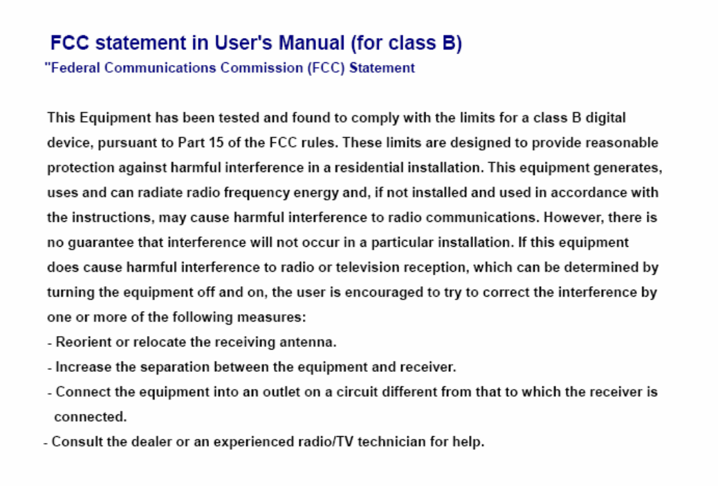
FCC Interference Statement
This equipment has been tested and found to comply with the limits for a Class B digital device
pursuant to Part 15 of the FCC Rules. These limits are designed to provide reasonable protection
against radio interference in a commercial environment. This equipment can generate, use and
radiate radio frequency energy and, if not installed and used in accordance with the instructions in
this manual, may cause harmful interference to radio communications. Operation of this
equipment in a residential area is likely to cause interference, in which case the user, at his own
expense, will be required to take whatever measures are necessary to correct the interference.
CE Declaration of Conformity
This equipment complies with the requirements related to electromagnetic compatibility, EN
55022/A1 Class B.
The specification is subject to change without notice.
FCC COMPLIANCE STATEMENT
Table of Contents
FCC Interference Statement........................................................................................ 2
1. Introduction............................................................................................................... 4
1.1. Package Contents...................................................................................... 4
1.2. System Requirements for Configuration................................................ 4
1.3. Interfaces - the Rear View........................................................................ 5
1.4. LEDs and Buttons – the Front View....................................................... 5
1.5. Features...................................................................................................... 6
2. Configuring WiFi Combo Broadband Gateway.............................................. 7
2.1. Installation Considerations...................................................................... 7
2.1.1. Installation Instructions- Get Start Networking.................................... 7
2.1.2. Establish WiFi Connection....................................................................... 9
3. Using the Configuration Menu .......................................................................... 10
3.1. Wizard setting ......................................................................................... 12
3.2. Administrator’s Main Menu.................................................................. 18
4. Troubleshooting................................................................................................... 55
5. Technical Specifications...................................................................................... 58

1. Introduction
The WiFi Combo Broadband Gateway is a high-performance tool that supports wireless
networking at home, work, or in a public place. The WiFi Combo Broadband Gateway supports
a USB 3G modem card, either WCDMA or EVDO and even HSDPA as well, and supports
wireless data transfers up to 150M bps, and wired data transfers up to 100 Mbps.
The WiFi Combo Broadband Gateway is compatible with industry security features.
1.1. Package Contents
Importance: Check your product package contents FIRST.
The WiFi Combo Broadband Gateway package should contain the items listed below. If any
of the items are missing, please contact your reseller.
items Description Quantity
1 WiFi Combo Broadband Gateway 1
2 RJ-45 Cable 1
3 Power adapter 5V 2.0A 1
4 CD 1
Caution: Using a power supply with a different voltage rating than the one included with the
WiFi Combo Broadband Gateway will cause damage and void the warranty for this product.
1.2. System Requirements for Configuration
• A compatible USB 3G modem card with service
Note: Subject to services and service terms available from your carrier.
• Computers with Windows, Macintosh, or Linux-based operating systems with an installed
Ethernet adapter.
• Internet Explorer version 6.0 or Netscape Navigator version 7.0 and above.
• Wi-Fi System Requirements: An 802.11b, 802.11g, or 802.11n Adapter.
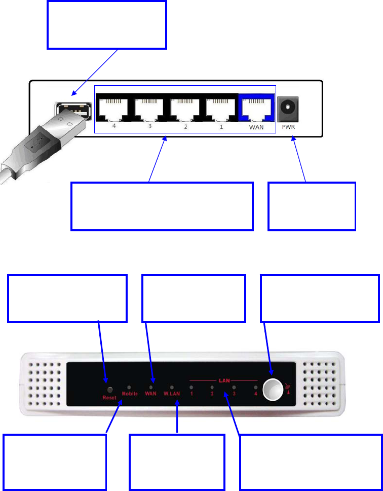
1.3. Interfaces - the Rear View
1.4. LEDs and Buttons – the Front View
Note:
Contains a reset button to restore the setting back to original factory defaulted setting as if your
convenience of forgetting your applicable setting
Reset Button
Restore to Original
factory defaulted setting
USB port for connecting
with 3G USB modem
Receptor for
Power adapter
Auto MDI/MDIX RJ-45 Ports
Automatically sense the types of WAN
and LAN when connecting to Ethernet
WPS Button
Restore to Original
factory defaulted setting
WiFi LED
A green light as
connection on
WLAN available
LAN LED
A green light as connected
to local Ethernet and blinks
durin
g
data is transmission
WAN LED
A green light as
WAN is connected
Mobile/Status LED
A green light as
what’s status of
p
ower or 3G card.
1.5. Features
z IEEE 802.11b/g compliant and 11n Lite (HW 1T1R not MIMO solution.)
Backward compatible to IEEE 802.11b standards
Max physical rate up to 54Mbps in 802.11g mode
Max physical rate up to 150Mbps in 802.11n mode
Security Supports: WEP (64/128 bits), WPA, WPA2, WPA-PSK,
WPA2-PSK, and 802.1x
WPS Support
z Provide 5 * 10/100 RJ-45 ports
4 * LAN
1 * WAN
z WAN connection through external USB 3G/3.75G modem card
WCDMA,HSDPA,HSUPA(depend on region)
CDMA2000,EV-DO(depend on region)
TD-SCDMA,TD-HSDPA(Option)
Flash OFDM(Reserve)
iBurst(Option)
z Built-in NAT function: one IP sharing with PCs
z Built-in firewall to protect your Intranet
z VPN pass through supported
PPTP
L2TP
IPSec
z Easy to upgrade firmware
Web UI
Windows utility
z Easy to manage:
Web UI
SNMP
UPnP
z Network Protocols
UDP/TCP/IP/ARP/RARP/ICMP
DHCP/PPPoE
DNS/TFTP/HTTP
z Antenna
1 x PiFa Wi-Fi antenna
Note: The WiFi Combo Broadband Gateway is designed to work with 3G USB dongle,
(either EVDO or WCDMA (UMTS)).
Please refer to your service provider for detailed feature information.
2. Configuring WiFi Combo Broadband Gateway
2.1. Installation Considerations
The WiFi Combo Broadband Gateway allows you access your network using a wireless
connection, from virtually anywhere within its operating range. Keep in mind however, that
the number, thickness, and location of walls, ceilings, or other objects that the wireless
signals must pass through, may limit this range.
Typical ranges vary depending on the types of materials used, and background RF (radio
frequency) noise in your home or business.
To maximize your wireless range, please follow these guidelines:
1. Keep the number of walls and ceilings between the WiFi Combo Broadband Gateway and
other network devices to a minimum. Each wall or ceiling can reduce the WiFi Combo
Broadband Gateway’s range from 3-90 feet (1-30 meters).
Note: The same considerations apply to your broadband EVDO connection.
2. Keep your product aware from electrical devices (such as microwaves, air conditioners,
and televisions) that emit large quantities of RFI (Radio Frequency Interference).
2.1.1. Installation Instructions- Get Start Networking
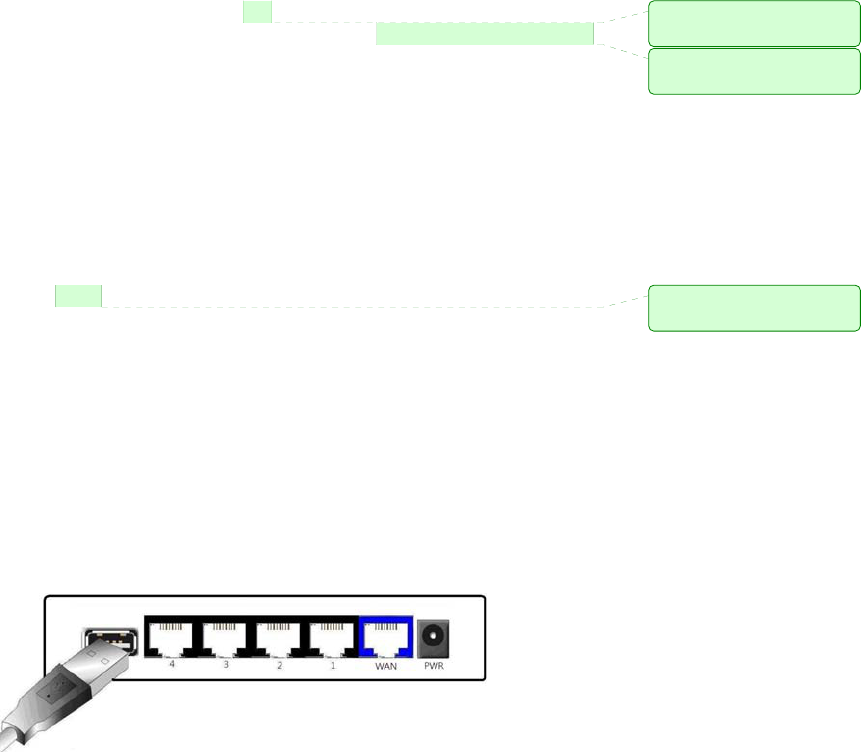
Connect this Gateway to Your Network
Note: DO NOT connect WiFi Combo Broadband Gateway to power before performing
the installation steps below.
1. Connect a USB modem with service to the WiFi Combo Broadband Gateway--
See Picture 2.1
Picture 2.1
Note: The WiFi Combo Broadband Gateway is designed to work with either
UMTS or EV-DO and even HSDPA 3G cards that can be used as a modem
(support tethered data). Please refer to your service provider for detailed feature
information.
註解 [01]: 加上 to
allow you to
註解 [02]: 應改為 However,
keep in mind that
註解 [03]: 應改為
away
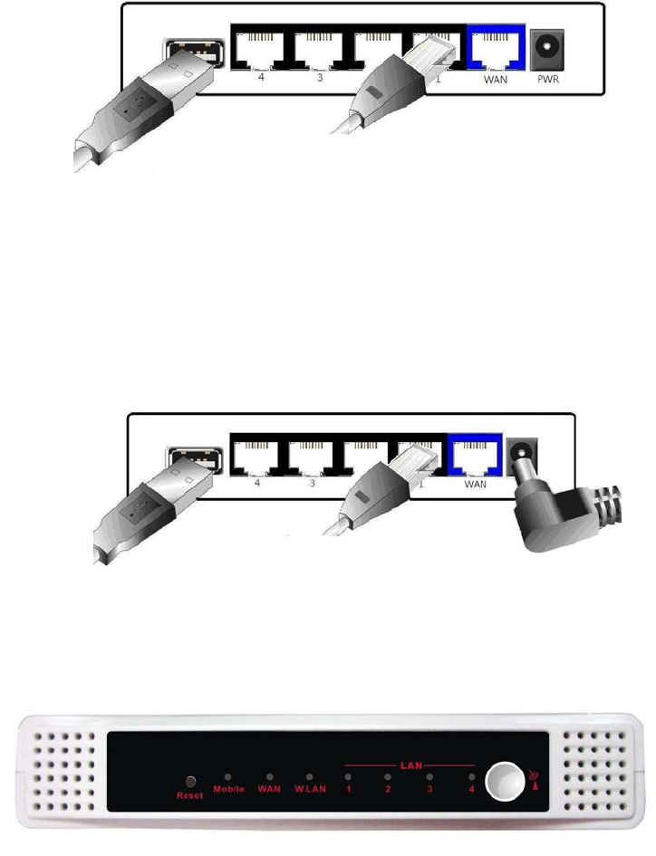
2. Insert the Ethernet patch cable into LAN Port on the back panel of the WiFi Combo
Broadband Gateway, and an available Ethernet port on the network adapter in the
computer you will use to configure the unit.-See Picture 2.2
Picture 2.2
Note: The WiFi Combo Broadband Gateway LAN Port is “Auto-MDI/MDIX.” This
provides patch Ethernet cable LAN Port access.
3. Connect the power adapter to the receptor on the back panel of your WiFi Combo
Broadband Gateway. Then plug the other end of the power adapter into a wall outlet
or power strip. –See Picture 2.3
Picture 2.3
4. The LEDs
Reference the Section 1.4, LEDs and Buttons– the Front View.

2.1.2. Establish WiFi Connection
If you selected either WEP or WPA-PSK encryption, ensure these settings match your
WiFi adapter settings.
WiFi and encryption settings must match for access to the WiFi Combo Broadband
Gateway Configuration Menu, and the Internet. Please refer to your WiFi adapter
documentation for additional information.
註解 [04]: 刪除 for
3. Using the Configuration Menu
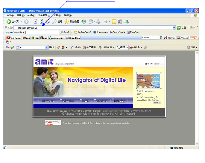
Once properly configured, the WiFi Combo Broadband Gateway will obtain and assign IP
address information automatically. Configuration settings can be established through the
WiFi Combo Broadband Gateway Configuration Menu. You can access this interface by
performing the steps listed below:
1. Open a web-browser.
2. Type in the IP Address (http://192.168.123.254) of the WiFi Combo Broadband Gateway.
Note: If you have changed the default IP Address assigned to the WiFi Combo Broadband
Gateway, ensure you enter the correct IP Address now.
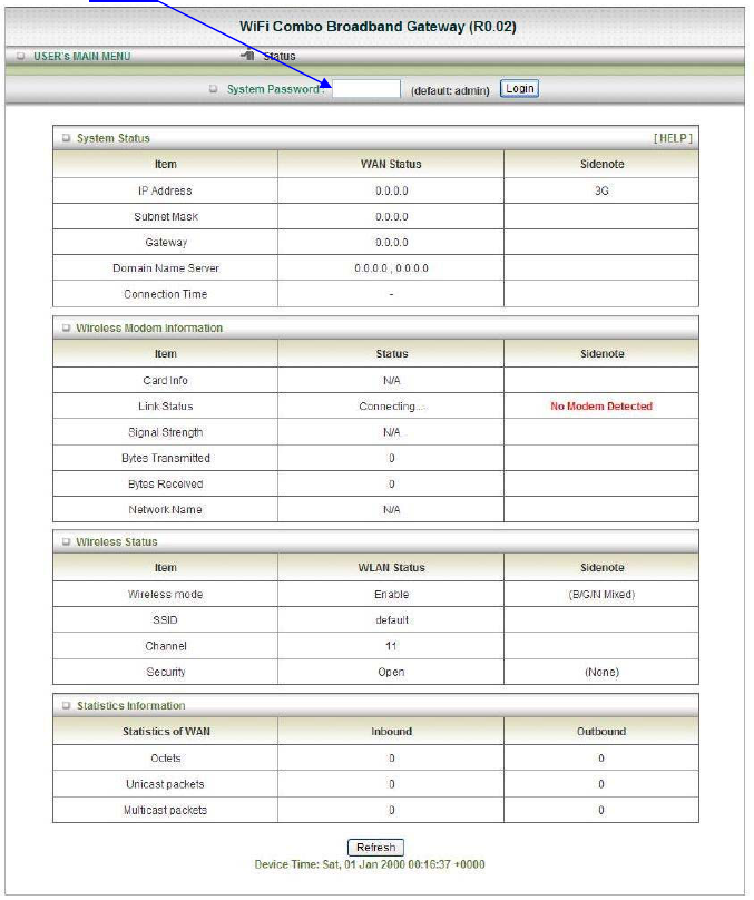
3. Type “admin” in the Password field.
4. Click “logon” button.
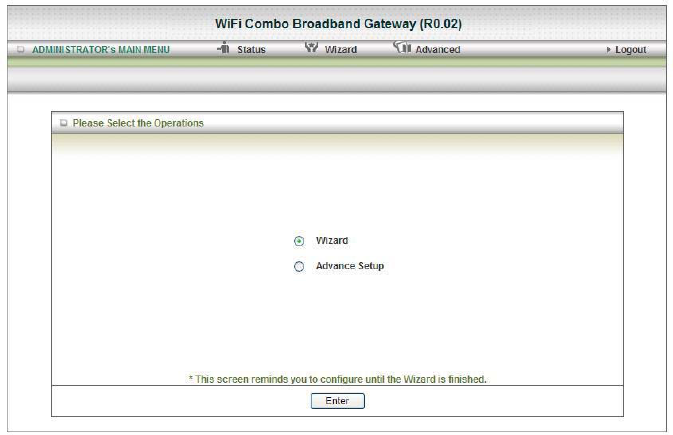
3.1. Wizard setting
z Press “Wizard” button Æ for basic settings with simpler way. (Please check section
3.1)
z Or you may click on “Advanced Setup” Æ for advanced settings. (Please check the
section Administrator’s Main Menu. each item from section 3.2)
z Click on “Enter” button to get start.
With wizard setting steps, you could configure the gateway in a very simple way. This
configuration wizard includes settings of
a. Login Password,
b. Time zone
c. WAN Setup
d. Wireless Setup,
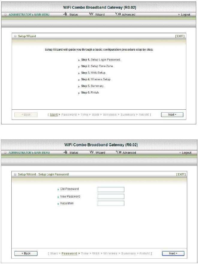
Press “Next” button to start configuration.
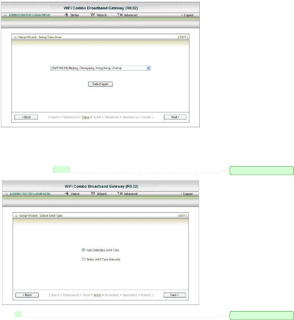
Step 1: Allow you to change the system password.
You can change Password here.
It is recommended that you change the system password into the one you prefer to on the basis of
security.
1. Key in your Old Password (if it is the first initiation, the “admin” will be the defaulted one.
2: Enter your New Password
3: Enter your Password again for confirmation; it must be the same as the New Password.
4. Then click on “Next” to get into next installation.
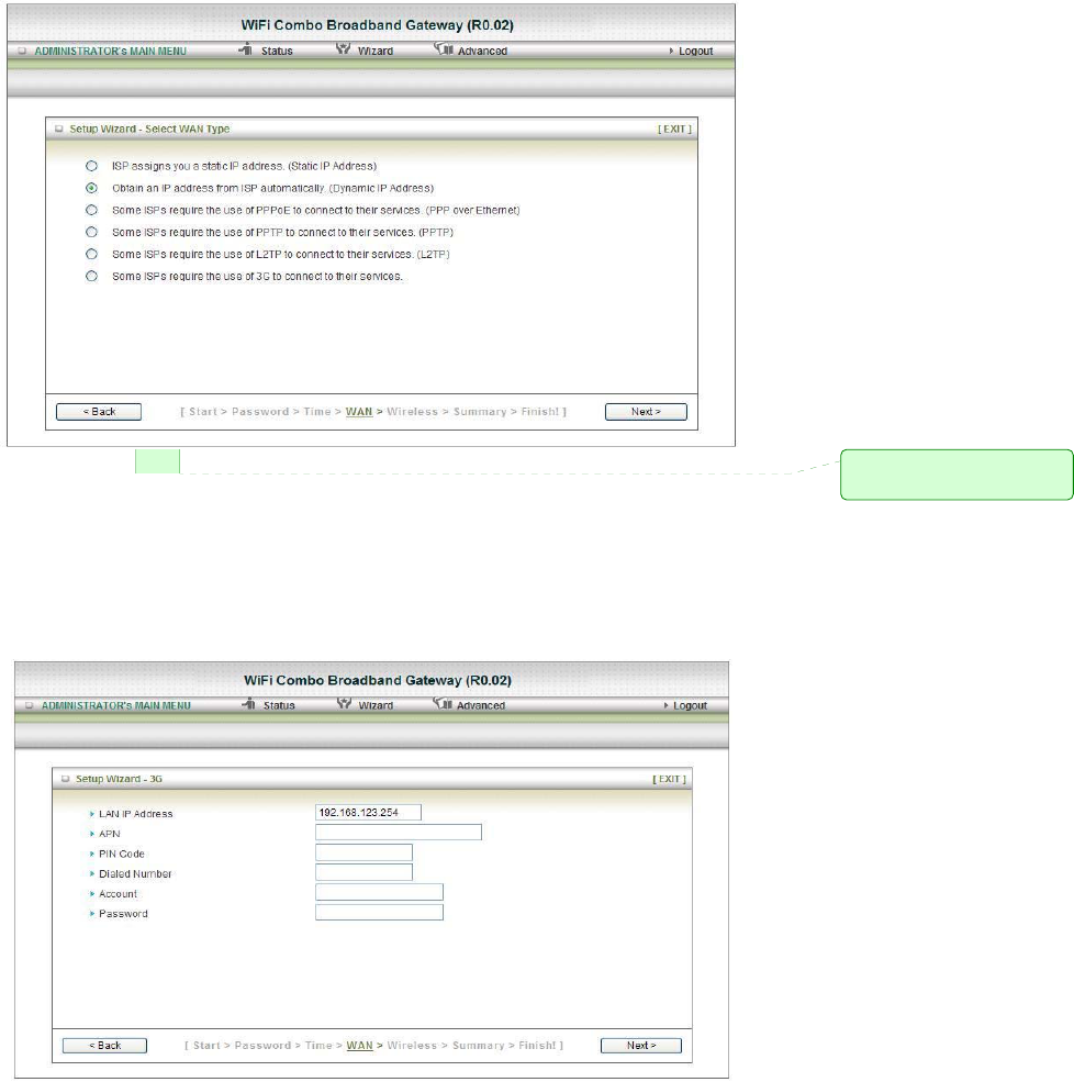
Step 2: Allow you to change the Time Zone.
You can change Time Zone here.
Or you can click the button “Detect Again”, the Time Zone will be changed to same with your PC.
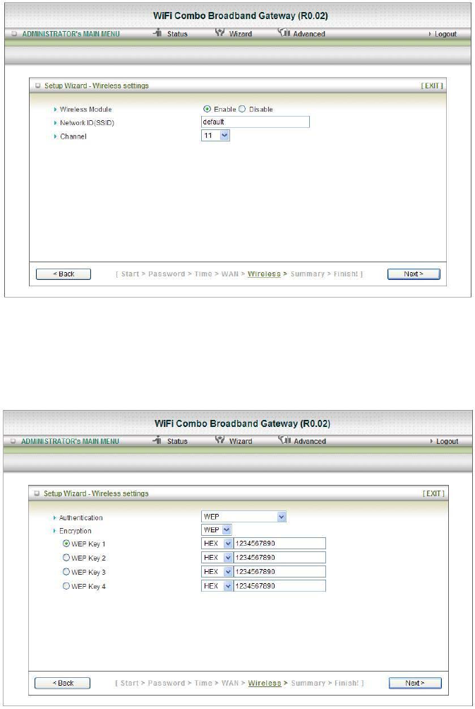
Step 3: Select WAN Types will be used for Internet connection
Step3-1: Auto Detecting & Manually Setting WAN Type
1. Reference Section 2.1 Installation Considerations to setup the environment
2. We are support the Dynamic & PPPOE WAN Type for Auto Detecting.
Click on “Next” button
註解 [05]: 刪除 will be
註解 [06]: 刪除 are
Step3-2: Select WAN Type
Pick up one of types you preferred to.
Click on “Next” button
You can select the Static, Dynamic, PPPOE, PPTP, L2TP and 3G WAN Types. We show
you How to setup the 3G WAN Type only.
Reference the Section 3.2.1.1 Primary Setup for more information
Step 3-3: Setup the 3G WAN will be used for Internet connection.
1. LAN IP Address: The IP address of the LAN interface. The default IP address is:
192.168.123.254
2. Enter the 3G Modem Card information by your 3G broadband service provider.
Click on “Next” button
註解 [07]: 加上 the
The types
Step 4: Configure the wireless settings.
1. Select “Enable” or “Disable”. The default setting is “Enable”.
2. Network ID (SSID) will be defaulted.
3. ChannelÆ Select Wireless Channel matching to your local area for Wireless connection.
4. Click on “Next” to continue.
Step 5: Select the Wireless security method of your wireless configuration.
1. Select “WEP” Security type and enter the WEP key.
2. Click on “Next” to continue.
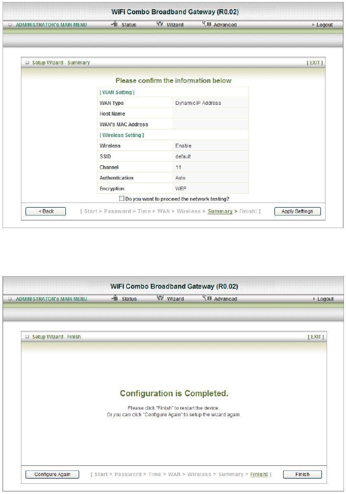
Step 6: Summary
Click on the “Apply Settings” button
Step 7: System is applying.
Click “Finish” button to back the Status Page.
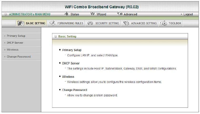
3.2. Administrator’s Main Menu
3.2.1 Basic Setting
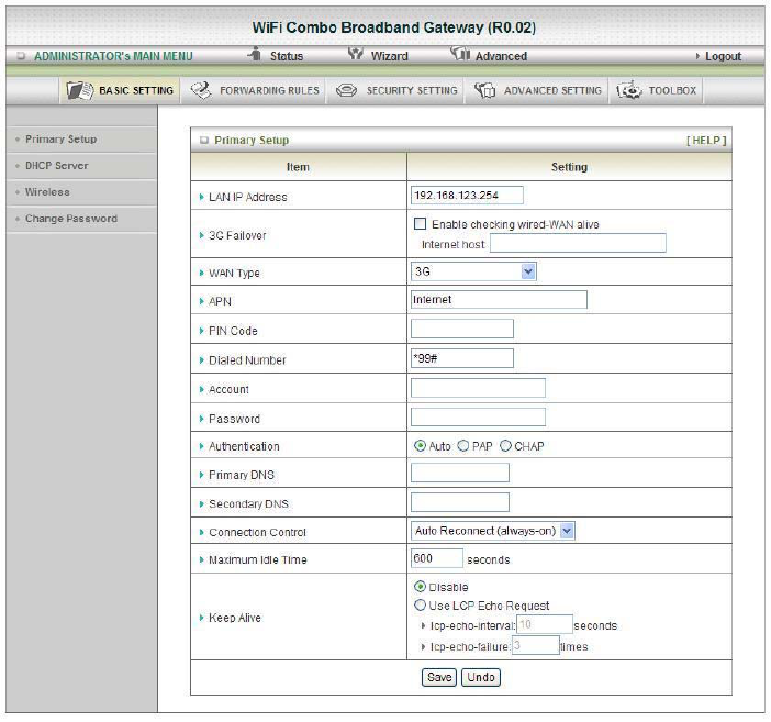
3.2.1.1 Primary Setup
1. LAP IP Address: the local IP address of this device. The computers on your network must use
the LAN IP address of your product as their Default Gateway. You can change it if necessary.
2. 3G Failover: The WAN type will be change to 3G automatically, if the internet host (to detect it
by wired WAN) is defunct.
3. WAN Type: WAN connection type of your ISP. You can click WAN Type HSPA button to
choose a correct one from the following options:
Static IP Address:
WAN IP Address, Subnet Mask, Gateway, Primary and Secondary DNS: enter the proper
setting provided by your ISP.
Dynamic IP Address:
1. Host Name: optional, required by some ISPs, for example, @Home.
2. ISP registered MAC address: You can change the WAN port MAC address, it is your ISP
assigned to you.
3. Connection Control: There are 3 modes to select:
Connect-on-demand: The device will link up with ISP when the clients send outgoing
packets.
Auto Reconnect (Always-on): The device will link with ISP until the connection is
established.
Manually: The device will not make the link until someone clicks the connect-button in
the Status-page.
4. NAT disable: NAT disable is enabling, it can bridge data form WAN port to LAN port.
PPP over Ethernet
1. PPPoE Account and Password: the account and password your ISP assigned to you. For
security, this field appears blank. If you don't want to change the password, leave it empty.
2. Connection Control: There are 3 modes to select:
Connect-on-demand: The device will link up with ISP when the clients send outgoing
packets.
Auto Reconnect (Always-on): The device will link with ISP until the connection is
established.
Manually: The device will not make the link until someone clicks the connect-button in
the Status-page.
3. Maximum Idle Time: the amount of time of inactivity before disconnecting your PPPoE
session. Set it to zero or enable Auto-reconnect to disable this feature.
4. PPPoE Service Name: optional. Input the service name if your ISP requires it. Otherwise,
leave it blank.
5. MTU (Maximum Transmission Unit): Most ISP offers MTU value to users. The default
value is 0 (Auto).
6. NAT disable: NAT disable is enabling, it can bridge data form WAN port to LAN port.
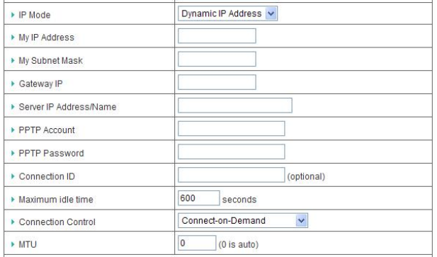
PPTP
First, please check your ISP assigned and Select Static IP Address or Dynamic IP Address. For
example: Use Static, the private My IP address, My subnet mask and Gateway are your ISP
assigned to you.
1. Server IP Address/Name: the IP address (or URL) of the PPTP server.
2. PPTP Account and Password: the account and password your ISP assigned to you. For
security, this field appears blank. If you don't want to change the password, keep it empty.
3. Connection ID: optional. Input the connection ID if your ISP requires it.
4. Maximum Idle Time: the time of no activity to disconnect your PPTP session. Set it to zero
or enable Auto-reconnect to disable this feature. If Auto-reconnect is enabled, this product
will connect to ISP automatically, after system is restarted or connection is dropped.
5. Connection Control: There are 3 modes to select:
Connect-on-demand: The device will link up with ISP when the clients send outgoing
packets.
Auto Reconnect (Always-on): The device will link with ISP until the connection is
established.
Manually: The device will not make the link until someone clicks the connect-button in
the Status-page.
6. MTU (Maximum Transmission Unit): Most ISP offers MTU value to users. The default
value is 0 (Auto).
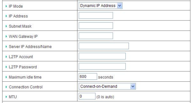
L2TP
First, please check your ISP assigned and Select Static IP Address or Dynamic IP Address. For
example: Use Static, the private IP address, subnet mask and WAN Gateway IP are your ISP
assigned to you.
1. Server IP Address/Name: the IP address (or URL) of the L2TP server.
2. L2TP Account and Password: the account and password your ISP assigned to you. For
security, this field appears blank. If you don't want to change the password, keep it empty.
3. Maximum Idle Time: the time of no activity to disconnect your L2TP session. Set it to zero
or enable Auto-reconnect to disable this feature. If Auto-reconnect is enabled, this product
will connect to ISP automatically, after system is restarted or connection is dropped.
4. Connection Control: There are 3 modes to select:
Connect-on-demand: The device will link up with ISP when the clients send outgoing
packets.
Auto Reconnect (Always-on): The device will link with ISP until the connection is
established.
Manually: The device will not make the link until someone clicks the connect-button in
the Status-page.
5. MTU (Maximum Transmission Unit): Most ISP offers MTU value to users. The default
value is 0 (Auto).
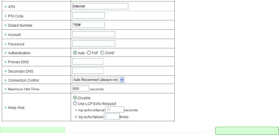
3G
For 3G WAN Networking. The WAN fields may not be necessary for your connection. The
information on this page will only be used when your service provider requires you to enter a
User Name and Password to connect to the 3G network.
Please refer to your documentation or service provider for additional information.
1. APN: Enter the APN for your PC card here.
2. Pin Code: Enter the Pin Code for your SIM card
3. Dial-Number: This field should not be altered except when required by your service
provider.
4. User Name: Enter the new User Name for your PC card here.
5. Password: Enter the new Password for your PC card here.
6. Primary DNS: This feature allows you to assign a Primary DNS Server(Optional)
7. Secondary DNS: This feature allows you to assign a Secondary DNS Server(Optional)
8. Connection Control: There are 3 modes to select:
Connect on Demand: The device will link up with ISP when the clients send outgoing
packets.
Auto Reconnect (always-on): The device will link with ISP until the connection is
established.
Manually: The device will not make the link until someone clicks the connect-button in
the Status-page.
9. Maximum Idle Time: The Connection will be broken when the idle time arrives.
10. Keep Alive: There are 2 modes to select:
Disable / Use LCP Echo Request.
註解 [08]: For…, the WAN….
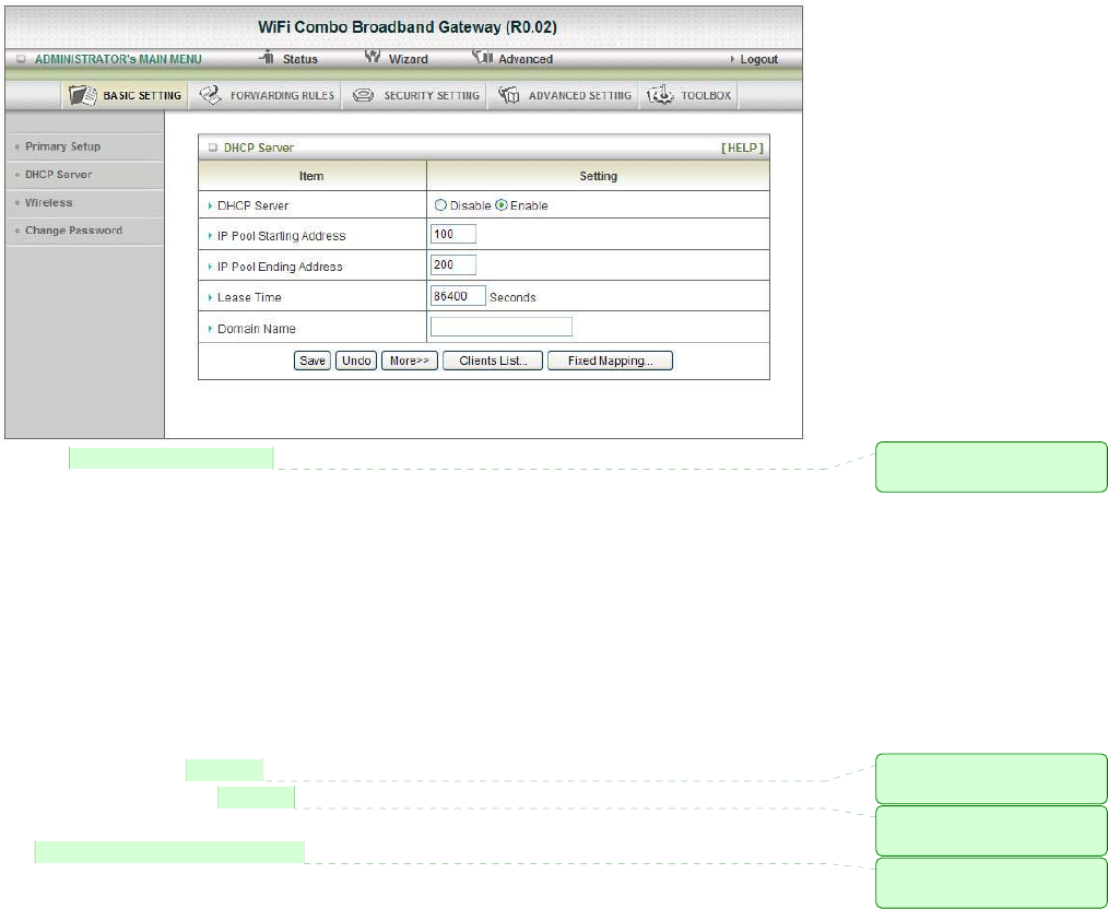
3.2.1.2 DHCP Server
1. Press “More>>”, for more settings.
2. DHCP Server: Choose either Disable or Enable.
3. IP Pool Starting/Ending Address: Whenever there is a request, the DHCP server will
automatically allocate an unused IP address from the IP address pool to the requesting computer.
You must specify the starting / ending address of the IP address pool.
4. Lease Time: DHCP lease time to the DHCP client.
5. Domain Name: Optional, this information will be passed to the client
6. Primary DNS/Secondary DNS: Optional, This feature allows you to assign a DNS Servers
7. Primary WINS/Secondary WINS: Optional, this feature allows you to assign a WINS Servers
8. Gateway: Optional, Gateway Address would be the IP address of an alternate Gateway.
This function enables you to assign another gateway to your PC, when DHCP server offers an IP
to your PC.
9. Clients List...: Reference the next Page “DHCP Clients List”.
10. Fixed Mapping...: Reference the next page “DHCP Fixed Mapping”.
After you finish your selection then
Either Click on “Save” to store what you just pick or click “Undo” to give up
註解 [09]: 應改為
Press… for more….
註解 [010]: 應該為
Refer to…….
註解 [011]: 應該為
Refer to….
註解 [012]: 應該為
After…, then……
DHCP Clients List
Delete: The selected items will be deleted.
Fixed Mapping: The selected items will be added to the Fix Mapping Table.
DHCP Fixed Mapping
The DHCP server will reserve the IP address for the Client, which have the MAC address.
註解 [013]: 應該為
has
3.2.1.3 Wireless Settings
Wireless settings allow you to set the wireless configuration items.
1. Wireless: Enabled is the default. Selecting this option will allow you to set your Wireless
Access Point (WAP) settings.
2. Network ID (SSID): Service Set Identifier (SSID) is the name designated for a specific
wireless local area network (WLAN). The SSID's factory default setting is default. The
SSID can be easily changed to establish a new wireless network. (Note: SSID names may
contain up to 32 ASCII characters).
3. SSID Broadcast: The gateway will broadcast beacons that have some information,
including ssid so that wireless clients can know how many AP devices by scanning
function in the network. Therefore, this function is disabled; the wireless clients can not
find the device from beacons.
4. Channel: Auto is the default. Devices on the network must share the same channel. (Note:
Wireless adapters automatically scan and match the wireless settings. You may also
select the channel you wish to use).
5. Wireless Mode: Choose B/G Mixed, B only, G only, N only, G/N Mixed or B/G/N mixed.
The factory default setting is B/G/N mixed.
6. Authentication: You may select from nine kinds of authentication to secure your wireless
network: Open, Shared, Auto, WPA-PSK, WPA, WPA2-PSK, WPA2,
WPA-PSK/WPA2-PSK, WPA/WPA2.

Open
Open system authentication simply consists of two communications. The first is an authentication
request by the client that contains the station ID (typically the MAC address). This is followed by
an authentication response from the AP/gateway containing a success or failure message. An
example of when a failure may occur is if the client's MAC address is explicitly excluded in the
AP/gateway configuration.
Shared
Shared key authentication relies on the fact that both stations taking part in the authentication
process have the same "shared" key or passphrase. The shared key is manually set on both the
client station and the AP/gateway. Three types of shared key authentication are available today for
home or small office WLAN environments.
Auto
The AP will Select the Open or Shared by the client’s request automatically.
WPA-PSK
Select Encryption and Pre-share Key Mode
If you select HEX, you have to fill in 64 hexadecimal (0, 1, 2…8, 9, A, B…F) digits.
If you select ASCII, the length of pre-share key is from 8 to 63.
Fill in the key, Ex 12345678
WPA
Check Box was used to switch the function of the WPA. When the WPA function is enabled, the
Wireless user must authenticate to this gateway first to use the Network service. RADIUS Server
IP address or the 802.1X server’s domain-name.
Select Encryption and RADIUS Shared Key
If you select HEX, you have to fill in 64 hexadecimal (0, 1, 2…8, 9, A, B…F) digits
If you select ASCII, the length of pre-share key is from 8 to 63.
Key value shared by the RADIUS server and this gateway. This key value is consistent with the
key value in the RADIUS server.
WPA-PSK2
WPA-PSK2 user AES and TKIP for Same the encryption, the others are same the WPA-PSK.
WPA2
WPA2 add uses AES and TKIP for encryption, the others are same the WPA.
WPA-PSK/WPA-PSK2
Another encryption options for WPA-PSK-TKIP and WPA-PSK2-AES, the others are same the
WPA-PSK.
WPA/WPA2
Another encryption options for WPA-TKIP and WPA2-AES, the others are same the WPA.
註解 [014]: 應改為
are same with
註解 [015]: 應改為 are same
with
註解 [016]: 應改為
are same with
WDS (Wireless Distribution System) Setting
WDS operation as defined by the IEEE802.11 standard has been made available. Using WDS it is possible
to wirelessly connect Access Points, and in doing so extend a wired infrastructure to locations where
cabling is not possible or inefficient to implement.
WPS (Wi-Fi Protection Setup)
WPS is Wi-Fi Protection Setup which is similar to WCN-NET and offers safe and easy way in Wireless
Connection.
Wireless Client List
The list of wireless client is shows here.
3.2.1.4 Change Password
You can change Password here. We strongly recommend you to change the system password for security
reason.
Click on “Save” to store what you just select or “Undo” to give up
註解 [017]: 應改為 shown
3.2.2 Forwarding Rules
3.2.2.1 Virtual Server
This product’s NAT firewall filters out unrecognized packets to protect your Intranet, so all hosts behind
this product are invisible to the outside world. If you wish, you can make some of them accessible by
enabling the Virtual Server Mapping.
A virtual server is defined as a Service Port, and all requests to this port will be redirected to the computer
specified by the Server IP. Virtual Server can work with Scheduling Rules, and give user more flexibility on
Access control. For Detail, please refer to Scheduling Rule.
For example, if you have an FTP server (port 21) at 192.168.123.1 and Scheduling Rule(0), a Web server
(port 80) at 192.168.123.2 and Scheduling Rule(1), a VPN server at 192.168.123.6 and Scheduling Rule(2),
then you need to specify the following virtual server mapping table:
註解 [018]: 字尾加上 s

Service Port Server IP Enable Scheduling
Rule
21 192.168.123.1 V 0
80 192.168.123.2 V 1
1723 192.168.123.6 V 2
Click on “Save” to store what you just select or “Undo” to give up
3.2.2.2 Special AP
Some applications require multiple connections, like Internet games, Video conferencing, Internet
telephony, etc. Because of the firewall function, these applications cannot work with a pure NAT router.
The Special Applications feature allows some of these applications to work with this product. If the
mechanism of Special Applications fails to make an application work, try setting your computer as the
DMZ host instead.
1. Trigger: the outbound port number issued by the application.
2. Incoming Ports: when the trigger packet is detected, the inbound packets sent to the specified
port numbers are allowed to pass through the firewall.
This product provides some predefined settings.
1. Select your application and
2. Click “Copy to” to add the predefined setting to your list.
Note! At any given time, only one PC can use each Special Application tunnel.
Click on “Save” to store what you just select or” Undo” to give up
3.2.2.3 Miscellaneous
1. IP Address of DMZ Host
DMZ (Demilitarized Zone) Host is a host without the protection of firewall. It allows a computer
to be exposed to unrestricted 2-way communication for Internet games, Video conferencing,
Internet telephony and other special applications.
2. UPnP Setting
The device also supports this function. If the OS supports this function enable it, like Windows XP.
When the user gets IP from Device and will see icon as below:
Click on “Save” to store what you just select or “Undo” to give up
註解 [019]: 刪除 and
改為…., they
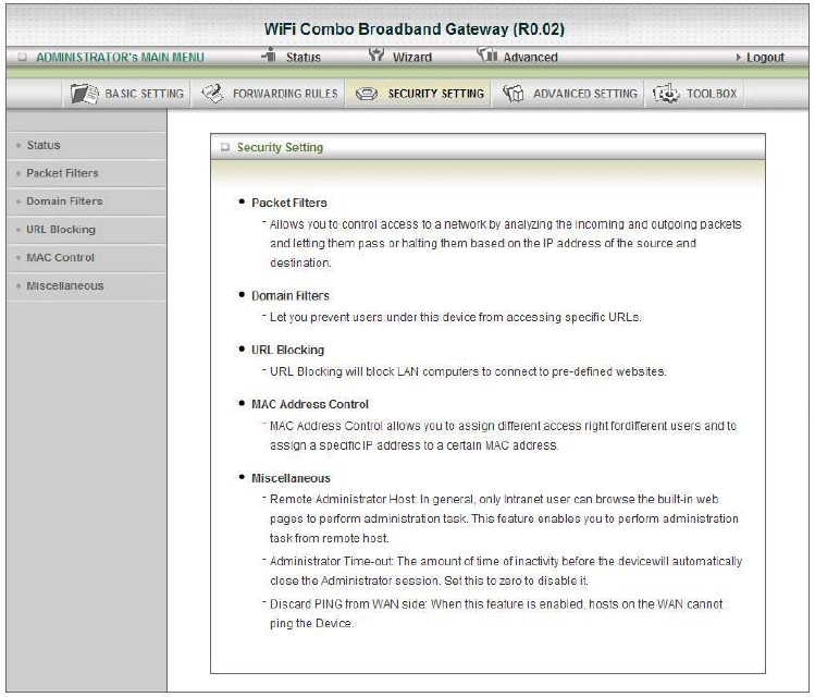
3.2.3 Security Setting
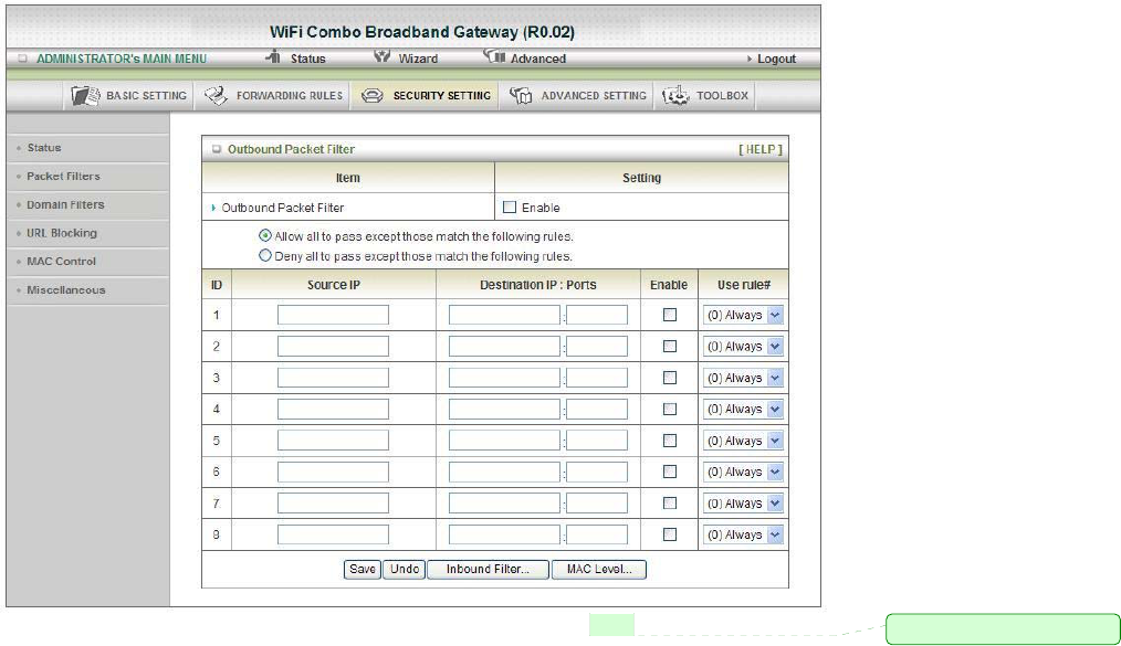
3.2.3.1 Packet Filters (Outbound & Inbound))
Packet Filter includes both outbound filter and inbound filter. And they have same way to setting.
Packet Filter enables you to control what packets are allowed to pass the gateway. Outbound filter applies
on all outbound packets. However, inbound filter applies on packets that destined to Virtual Servers or
DMZ host only. You can select one of the two filtering policies:
1. Allow all to pass except those match the specified rules
2. Deny all to pass except those match the specified rules
You can specify 8 rules for each direction: inbound or outbound. For each rule, you can define the
following:
• Source IP address
• Source port
• Destination IP address
• Destination port
• Protocol: TCP or UDP or both.
• Use Rule#
For source or destination IP address, you can define a single IP address (4.3.2.1) or a range of IP addresses
(4.3.2.1-4.3.2.254). An empty implies all IP addresses.
For source or destination port, you can define a single port (80) or a range of ports (1000-1999). Add prefix
"T" or "U" to specify TCP or UDP protocol. For example, T80, U53, U2000-2999, No prefix indicates both
TCP and UDP are defined. An empty implies all port addresses. Packet Filter can work with Scheduling
Rules, and give user more flexibility on Access control. For Detail, please refer to Scheduling Rule.
註解 [020]: 應改為 the same
Each rule can be enabled or disabled individually.
Click on “Save” to store what you just select or “Undo” to give up
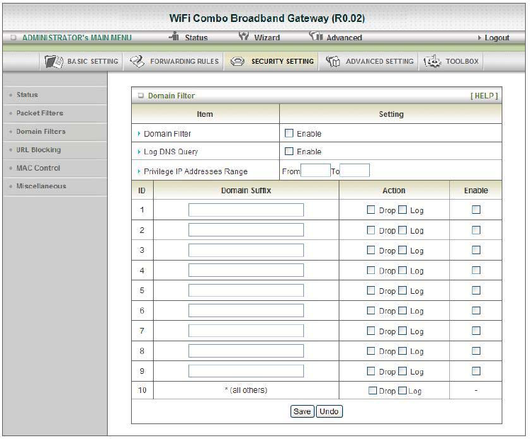
3.2.3.2 Domain Filters
1. Domain Filter
Let you prevent users under this device from accessing specific URLs.
2. Domain Filter Enable
Check if you want to enable Domain Filter.
3. Log DNS Query
Check if you want to log the action when someone accesses the specific URLs.
4. Privilege IP Address Range
Setting a group of hosts and privilege these hosts to access network without restriction.
5. Domain Suffix
A suffix of URL can be restricted, for example, ".com", and “xxx.com".
6. Action
When someone is accessing the URL met the domain-suffix, what kind of action you want.
Check drop to block the access. Check “log” to log these access.
7. Enable
Check to enable each rule.
Click on “Save” to store what you just select or “Undo” to give up
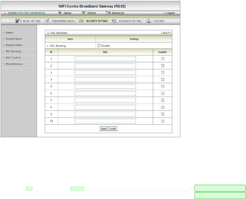
3.2.3.3 URL Blocking
URL Blocking will block LAN computers to connect to pre-define Websites. The major difference between
“Domain filter” and “URL Blocking” is Domain filter require user to input suffix (like .com or .org, etc),
while URL Blocking require user to input a keyword only. In other words, Domain filter can block specific
website, while URL Blocking can block hundreds of websites by simply a keyword.
1. URL Blocking Enable
Check if you want to enable URL Blocking.
2. URL
If any part of the Website's URL matches the pre-defined word, the connection will be blocked.
For example, you can use pre-defined word "sex" to block all websites if their URLs contain
pre-defined word "sex".
3. Enable
Check to enable each rule.
Click on “Save” to store what you just select or “Undo” to give up
註解 [021]: 字尾加上 s
註解 [022]: 刪除 s
3.2.3.4 MAC Control
MAC Address Control allows you to assign different access right for different users and to assign a specific
IP address to a certain MAC address.
1. MAC Address Control
Check “Enable” to enable the “MAC Address Control”. All of the settings in this page will take
effect only when “Enable” is checked.
2. Connection control
Check "Connection control" to enable the controlling of which wired and wireless clients can
connect to this device. If a client is denied to connect to this device, it means the client can't access
to the Internet either. Choose "allow" or "deny" to allow or deny the clients, whose MAC
addresses are not in the "Control table" (please see below), to connect to this device.
3. Association control
Check "Association control" to enable the controlling of which wireless client can associate to the
wireless LAN. If a client is denied to associate to the wireless LAN, it means the client can't send
or receive any data via this device. Choose "allow" or "deny" to allow or deny the clients, whose
MAC addresses are not in the "Control table", to associate to the wireless LAN
Click on “Save” to store what you just select or “Undo” to give up
Click on “Next Page” to go down or “Previous page” back to last page
註解 [023]: 刪除逗點且應該
為小寫 choose
註解 [024]: 應改為
controllable
3.2.3.5 Miscellaneous
1. Administrator Time-out
The time of no activity to logout automatically, you may set it to zero to disable this feature.
2. Remote Administrator Host/Port
In general, only Intranet user can browse the built-in web pages to perform administration task.
This feature enables you to perform administration task from remote host. If this feature is enabled,
only the specified IP address can perform remote administration. If the specified IP address is
0.0.0.0, any host can connect to this product to perform administration task. You can use subnet
mask bits "/nn" notation to specified a group of trusted IP addresses for example, "10.1.2.0/24".
NOTE: When Remote Administration is enabled, the web server port will be shifted to 80. You
can change web server port to other port, too.
3. Discard PING from WAN side
When this feature is enabled, any host on the WAN cannot ping this product.
4. DoS Attack Detection
When this feature is enabled, the gateway will detect and log the DoS attack comes from the
Internet. Currently, the gateway can detect the following DoS attack: SYN Attack, Win Nuke, Port
Scan, Ping of Death, Land Attack etc.
Click on “Save” to store what you just select or” Undo” to give up
註解 [025]: 應改為 coming
3.2.4 Advanced Setting
3.2.4.1 System Log
This page supports two methods to export system logs to specific destination by means of syslog (UDP)
and SMTP (TCP). The items you have to setup including:
1. IP Address for Syslog
Host IP of destination where syslog will be sent to.
Check Enable to enable this function.
2. E-mail Alert Enable
Check if you want to enable Email alert (send syslog via email).
A. SMTP Server IP and Port
Input the SMTP server IP and port, which are concated with ':'. If you do not specify port number,
the default value is 25.
For example, "mail.your_url.com" or "192.168.1.100:26".
B. SMTP Username/Password
The username and password login the SMTP server.
C. E-mail address
The recipients who will receive these logs, you can assign more than 1 recipient, using ';' or ',' to
separate these email addresses.
D. E-mail Subject
The subject of email alert, this setting is optional.
3. View Log...:
Reference the Section 3.2.5.1 System Info.
Click on “Save” to store what you just select or “Undo” to give up
註解 [026]: 應改為
註解 [027]: 應改為
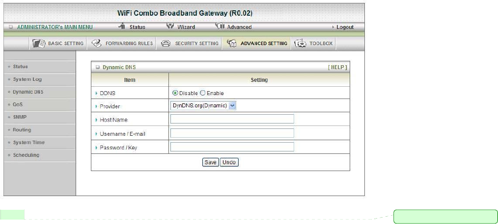
3.2.4.2 Dynamic DNS
To host your server on a changing IP address, you have to use dynamic domain name service (DDNS).
So that anyone wishing to reach your host only needs to know the name of it. Dynamic DNS will map the
name of your host to your current IP address, which changes each time you connect your Internet service
provider.
Before you enable Dynamic DNS, you need to register an account on one of these Dynamic DNS servers
that we list in provider field.
To enable Dynamic DNS click the check box next to Enable in the DDNS field.
Next you can enter the appropriate information about your Dynamic DNS Server.
You have to define:
Provider
Host Name
Username/E-mail
Password/Key
You will get this information when you register an account on a Dynamic DNS server.
Click on “Save” to store what you just select or “Undo” to give up
註解 [028]: 應改為Therefore,
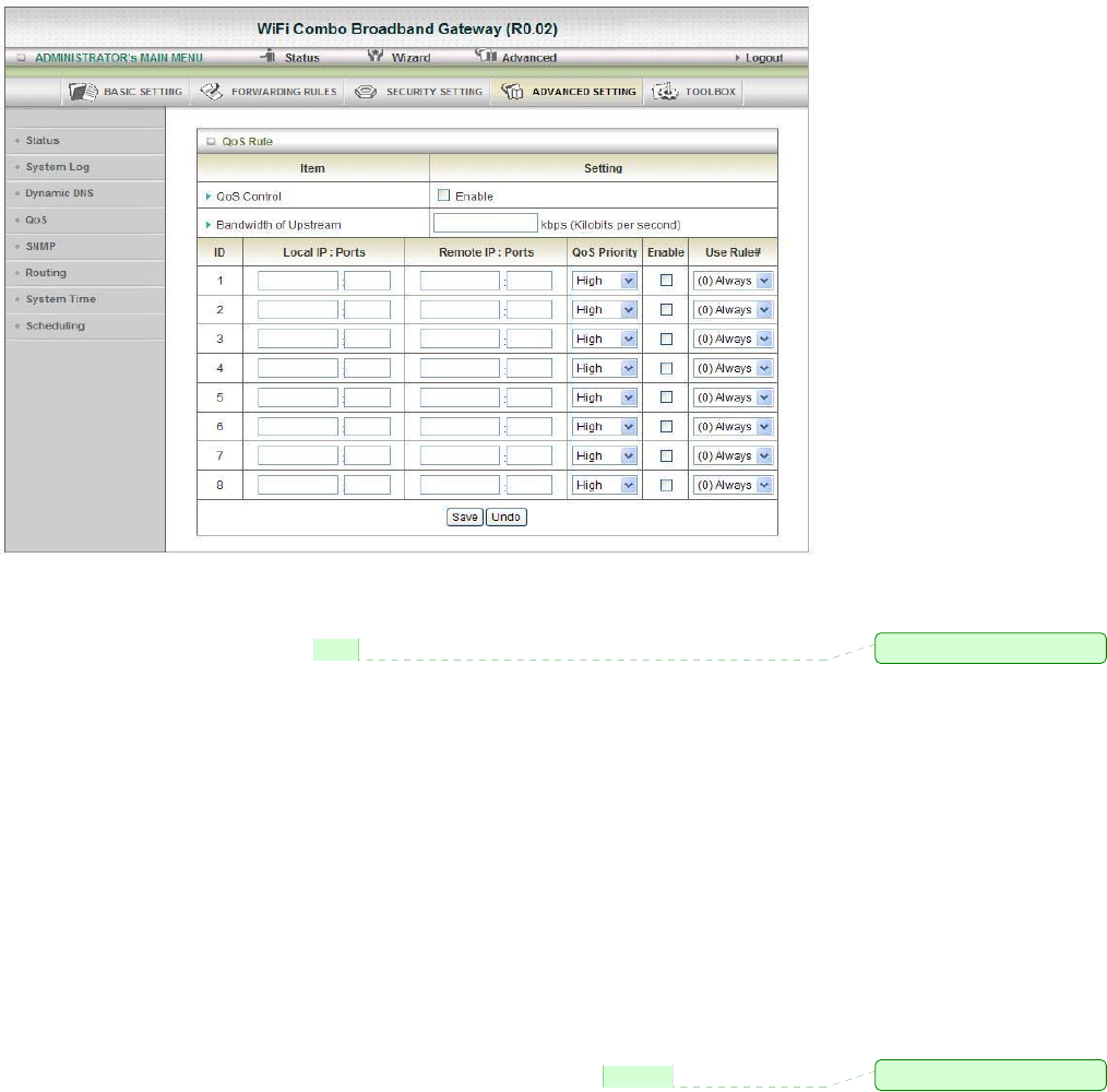
3.2.4.3 QOS
Provide different priority to different users or data flows, or guarantee a certain level of performance.
1. Enable
This Item enables QoS function or not.
2. Bandwidth of Upstream
Set the limitation of upstream speed.
3. Local: IP
Define the Local IP address of packets here.
4. Local: Ports
Define the Local port of the packets in this field.
5. Remote: IP
Define the Remote IP address of packets here.
6. Remote: Ports
Define the Remote port of the packets in this field.
7. QoS Priority
This defines the priority level of the current Policy Configuration. Packets associated with this
policy will be serviced based upon the priority level set. For critical applications High or Normal
levels are recommended. For non-critical applications select a Low level.
8. User Rule#
The QoS item can work with Scheduling Rule number#. Please reference the section 4.7.7
schedule.
Click on “Save” to store what you just select or “Undo” to give up
註解 [029]: 刪除
註解 [030]: 應改為 refer to
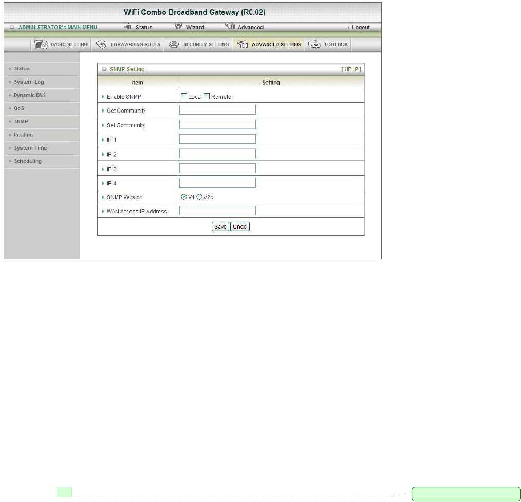
3.2.4.4 SNMP
In brief, SNMP, the Simple Network Management Protocol, is a protocol designed to give a user the
capability to remotely manage a computer network by polling and setting terminal values and monitoring
network events.
1. Enable SNMP
You must check Local, Remote or both to enable SNMP function. If Local is checked, this device
will response request from LAN. If Remote is checked, this device will response request from
WAN.
2. Get Community
Setting the community of Get Request your device will response.
3. Set Community
Setting the community of Set Request your device will accept.
IP 1, IP 2, IP 3, IP 4
Input your SNMP Management PC’s IP here. User has to configure to where this device should
send SNMP Trap message.
4. SNMP Version
Please select proper SNMP Version that your SNMP Management software supports.
5. WAN Access IP Address
If the user wants to limit to specific the IP address to access, please input in the item. The default
0.0.0.0 and means every IP of Internet can get some information of device with SNMP protocol.
Click on “Save” to store what you just select or “Undo” to give up.
註解 [031]: 刪除 and
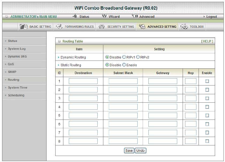
3.2.4.5 Routing
1. Routing Tables
Allow you to determine which physical interface address to use for outgoing IP data grams. If you
have more than one routers and subnets, you will need to enable routing table to allow packets to
find proper routing path and allow different subnets to communicate with each other.
Routing Table settings are settings used to setup the functions of static and dynamic routing.
2. Dynamic Routing
Routing Information Protocol (RIP) will exchange information about destinations for computing
routes throughout the network. Please select RIPv2 only if you have different subnet in your
network. Otherwise, please select RIPv1 if you need this protocol.
3. Static Routing
For static routing, you can specify up to 8 routing rules. You can enter the destination IP address,
subnet mask, gateway, hop for each routing rule, and then enable or disable the rule by checking or
un-checking the Enable checkbox.
Click on “Save” to store what you just select or “Undo” to give up.
3.2.4.6 System Time
1. Time Zone
Select a time zone where this device locates.
2. Time Server
Select a NTP time server to consult UTC time
3. Auto-Synchronization
Select the “Enable” item to enable this function.
4. Sync with Time Server
Select if you want to set Date and Time by NTP Protocol.
5. Sync with my PC
Select if you want to set Date and Time using PC’s Date and Time
Click on “Save” to store what you just select or “Undo” to give up.
3.2.4.7 Scheduling
You can set the schedule time to decide which service will be turned on or off.
Select the “Enable” item. Press “Add New Rule” You can write a rule name and set which day and what
time to schedule from “Start Time” to “End Time”.
The following example configure “ftp time” as “The ftp Protocol can be run everyday 14:10 to 16:20”.
Click on “Save” to store what you just select.
3.2.5 Tool Box
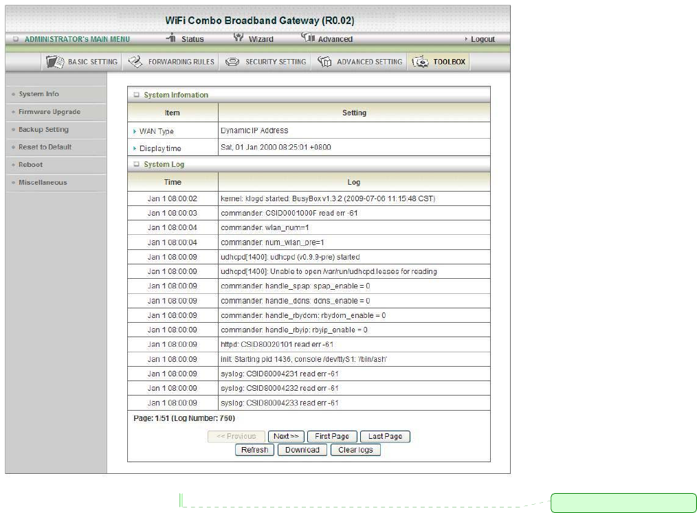
3.2.5.1 System Info
You can view the System Information and System log.
And download/clear the System log, in this page.
註解 [032]: 刪除逗號
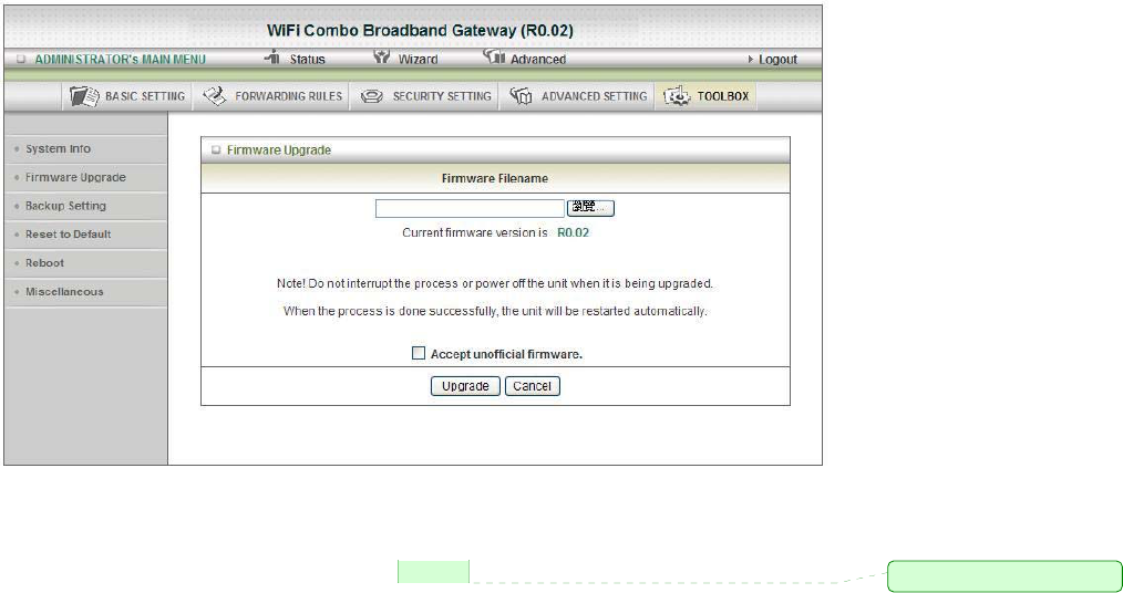
3.2.5.2 Firmware Upgrade
You can upgrade firmware by clicking “Upgrade” button.
3.2.5.3 Backup Setting
You can backup your settings by clicking the “Backup Setting” button and save it as a bin file.
Once you want to restore these settings, please reference the Section 3.2.5.2 Firmware Upgrade.
3.2.5.4 Reset to Default
You can also reset this product to factory default by clicking the Reset to default button.
3.2.5.5 Reboot
You can also reboot this product by clicking the Reboot button.
註解 [033]: 應改為 refer to
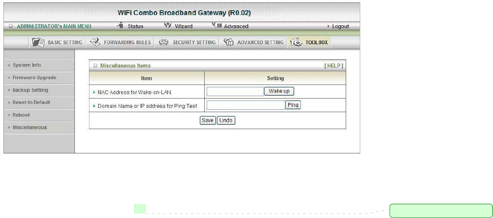
3.2.5.6 Miscellaneous
1. MAC Address for Wake-on-LAN
Wake-on-LAN is a technology that enables you to power up a networked device remotely. In order
to enjoy this feature, the target device must be Wake-on-LAN enabled and you have to know the
MAC address of this device, say 00-11-22-33-44-55. Clicking "Wake up" button will make the
gateway to send the wake-up frame to the target device immediately.
2. Domain Name or IP address for Ping Test
You can key in URL or IP address, and then click the “Ping” button for test.
註解 [034]: 應改為 saying

Troubleshooting
This section provides an overview of common issues, and possible solutions for the installation
and operation of the WiFi Combo Broadband Gateway.
1. Unable to access the Configuration Menu when I use my computer to configure the gateway. Why?
Note: It is recommended that you use an Ethernet connection to configure the
Ensure that the Ethernet LED on the WiFi Combo Broadband Gateway is ON.
If the LED is NOT ON, check to see if the cable for the Ethernet connection is securely inserted.
Note: Ensure that the IP Address is in the same range and subnet as the WiFi Combo
Broadband Gateway. The IP Address of the WiFi Combo Broadband Gateway is
192.168.123.254. All the computers on the network must have a unique IP Address within
the same range (e.g., 192.168.123.x). Any computers that have identical IP Addresses will
not be visible on the network. All computers must also have the same subnet mask (e.g.,
255.255.255.0).
Do a Ping test to make sure that the WiFi Combo Broadband Gateway is responding.
Go to Start > Run.
1: Type cmd.
2: Press Enter.
3: Type “ping 192.168.123.254”. A successful ping shows four replies.
Note: If you have changed the default IP Address, ensure you ping the correct IP Address
assigned to the WiFi Combo Broadband Gateway.
Ensure that your Ethernet Adapter is working properly, and that all network drivers are installed
properly.
Note: Network adapter names will vary depending on your specific adapter. The installation
steps listed below are applicable for all network adapters.
1. Go to Start > My Computer > Properties.
2. Select the Hardware Tab.
3. Click Device Manager.
4. Double-click on “Network Adapters”.
5. Right-click on Wireless Card bus Adapter, or your specific network adapter.
6. Select Properties to ensure that all drivers are installed properly.
7. Look under Device Status to see if the device is working properly.
8. Click “OK”.
2: Why my wireless client can NOT access the Internet?
Note: Establish WiFi Connection. As long as you select either WEP or WPA-PSK encryption,
ensure encryption settings match your WiFi settings. Please refer to your WiFi adapter
documentation for additional information.
Ensure that the wireless client is associated and joined with the correct Access Point.
To check this connection, follow the steps below:
1. Right-click on the Local Area Connection icon in the taskbar.
2. Select View Available Wireless Networks in Wireless Configure. The Connect to Wireless
Network screen appears. Ensure you have selected the correct available network.
註解 [035]: 沒有句點

Ensure the IP Address assigned to the wireless adapter is within the same subnet as the Access
Point and gateway. The WiFi Combo Broadband Gateway has an IP Address of
192.168.123.254. Wireless adapters must have an IP Address in the same range (e.g.,
192.168.123.x). Although the subnet mask must be the same for all the computers on
the network, no two devices may have the same IP Address. Therefore, each device must have
a unique IP Address.
To check the IP Address assigned to the wireless adapter, follow the steps below:
1. Enter ipconfig /all in command mode
2. Enter ping 192.168.123.254.to check if you can access the WiFi Combo Broadband
Gateway.
3. Why does my wireless connection keep dropping?
You may try following steps to solve.
• Antenna Orientation.
1: Try different antenna orientations for the WiFi Combo Broadband Gateway.
2: Try to keep the antenna at least 6 inches away from the wall or other objects.
• Try changing the channel on the WiFi Combo Broadband Gateway, and your Access Point
and Wireless adapter to a different channel to avoid interference.
• Keep your product away (at least 3-6 feet) from electrical devices that generate RF noise,
like microwaves, monitors, electric motors, etc.
4. Why I am unable to achieve a wireless connection?
Note: An Ethernet connection is required to troubleshoot the WiFi Combo Broadband
Gateway.
If you have enabled Encryption on the WiFi Combo Broadband Gateway, you must also
enable encryption on all wireless clients in order to establish a wireless connection.
• For 802.11g, the encryption settings are: 64 or 128 bit. Ensure that the encryption bit level
is the same for both the WiFi Combo Broadband Gateway, and your Wireless Client.
• Ensure that the SSID (Service Set Identifier) on the WiFi Combo Broadband Gateway and
the Wireless Client are exactly the same.
If they are not, your wireless connection will not be established.
• Move the WiFi Combo Broadband Gateway and the wireless client into the same room,
and then test the wireless connection.
• Disable all security settings such as WEP, and MAC Address Control.
• Turn off the WiFi Combo Broadband Gateway and the client.
Turn the WiFi Combo Broadband Gateway back on again, and then turn on the client.
• Ensure that all devices are set to Infrastructure mode.
• Ensure that the LED indicators are indicating normal activity. If not, ensure that the AC
power and Ethernet cables are firmly connected.
• Ensure that the IP Address, subnet mask, gateway and DNS settings are correctly entered
for the network.
• If you are using 2.4GHz cordless phones, X-10 equipment, or other home security systems,
ceiling fans, or lights, your wireless connection may degrade dramatically, or drop
altogether.
To avoid interference, change the Channel on the WiFi Combo Broadband Gateway, and all
devices in your network.
• Keep your product at least 3-6 feet away from electrical devices that generate RF noise.
註解 [036]: 應改為 am I

Examples include: microwaves, monitors, electric motors, and so forth.
5. I just do not remember my encryption key. What should I do?
• If you forgot your encryption key, the WiFi card will be unable to establish a proper connection.
If an encryption key setting has been set for the WiFi Combo Broadband Gateway, it must also
be set for the WiFi card that will connect to the WiFi Combo Broadband Gateway.
To reset the encryption key(s), login to the WiFi Combo Broadband Gateway using a wired
connection. (Please refer to “Basic > Wireless (Security–No Encryption)” on page 10, for
additional information).
7. How do I reset my WiFi Combo Broadband Gateway to its factory default settings?
If other troubleshooting methods have failed, you may choose to Reset the WiFi Combo
Broadband Gateway to its factory default settings.
To hard-reset the WiFi Combo Broadband Gateway its factory default settings, follow the steps
listed below:
1. Ensure the WiFi Combo Broadband Gateway is powered on
2. Locate the Reset button on the back of the WiFi Combo Broadband Gateway.
3. Use a paper clip to press the Reset button.
4. Hold for 10 seconds and then release.
5. After the WiFi Combo Broadband Gateway reboots, it is reset to the factory default settings.
Note: Please note that this process will take a few minutes.
8. What is VPN?
• VPN stands for “Virtual Private Networking.” VPNs create a "tunnel" through an existing
Internet connection using PPTP (Point-to-Point Tunneling Protocol) or IPSec (IP Security)
protocols with various encryption schemes including Microsoft Challenge Handshake
Authentication Protocol (MS-CHAP).
• This feature allows you to use your existing Internet connection to connect to a remote site with
added security. If your VPN connection is not functional, verify that your VPN dial-up
configuration is correct.
Note: This information should be provided to you from your VPN provider.
Pressing the Reset Button restores to its original factory default settings.
9. What can I do if my Ethernet cable does not work properly?
• First, ensure that there is a solid cable connection between the Ethernet port on the gateway, and
your NIC (Network Interface Card).
• Second, ensure that the settings on your NIC adapter are “Enabled,” and set to accept an IP
address from the DHCP.
• If settings appear to be correct, ensure that you are not using a crossover Ethernet cable.
Although the WiFi Combo Broadband Gateway is MDI/MDIX compatible, not all NICs are.
Therefore, it is recommended that you use a patch cable when possible.
Technical Support 45
註解 [037]: 應在 be 動詞後面

4. Technical Specifications
3G Access USB port
Standards IEEE 802.11b/g
IEEE 802.3
IEEE 802.3u
Wireless
Standard IEEE 802.11 B\G\N
Data Rate 11B: 11, 5.5, 2, 1 Mbps
11G: 54, 48, 36, 24, 18, 12, 9, and 6 Mbps
11N: Max physical rate up to 150Mbps
Frequency 2.4 – 2.462 GHz, CCK / OFDM modulation
Range Coverage Indoors approx. 30-50 meters;
Outdoors up to 80-100 meters
# of Channels 1-11 for N. America (FCC);1-11 for Canada (DOC)
1-13 Europe (Except Spain and France) (ETSI)
1-14 Japan (TELEC);
Security 64-bit and 128-bit WEP Encryption; WPA encryption
Antenna PIFA Antenna.
Firewall IP Filtering
NAT (Network Address Translation) with VPN Pass through
MAC Filtering
Supported WAN type 3G,Static IP, Dynamic IP, PPPoE,PPTP,L2TP
Connection Scheme Connect-on-demand, Auto-Disconnect
NAT function Class C ;One-to-Many; Max 253 Users; Virtual Server; DMZ Host
VPN PPTP, L2TP and IPSec Pass Through
Config.&
Management
Web-Based IE, Navigator browser and SNMP
IP assignment DHCP Server and Client
Working
Environment
Temperature: 0~40oC, Humidity 10%~90% non-condensing
OS supported Windows 95/98/ME/NT/2000/XP; Linux
Power Full range(100-240V), Switching 5V 2.0A