Advance Multimedia Internet Technology ISL500001 IIoT 4G User Manual UM IDG500 IOG500
Advance Multimedia Internet Technology Inc. IIoT 4G UM IDG500 IOG500
Contents
- 1. Users Manual-1.pdf
- 2. Users Manual-2.pdf
Users Manual-1.pdf
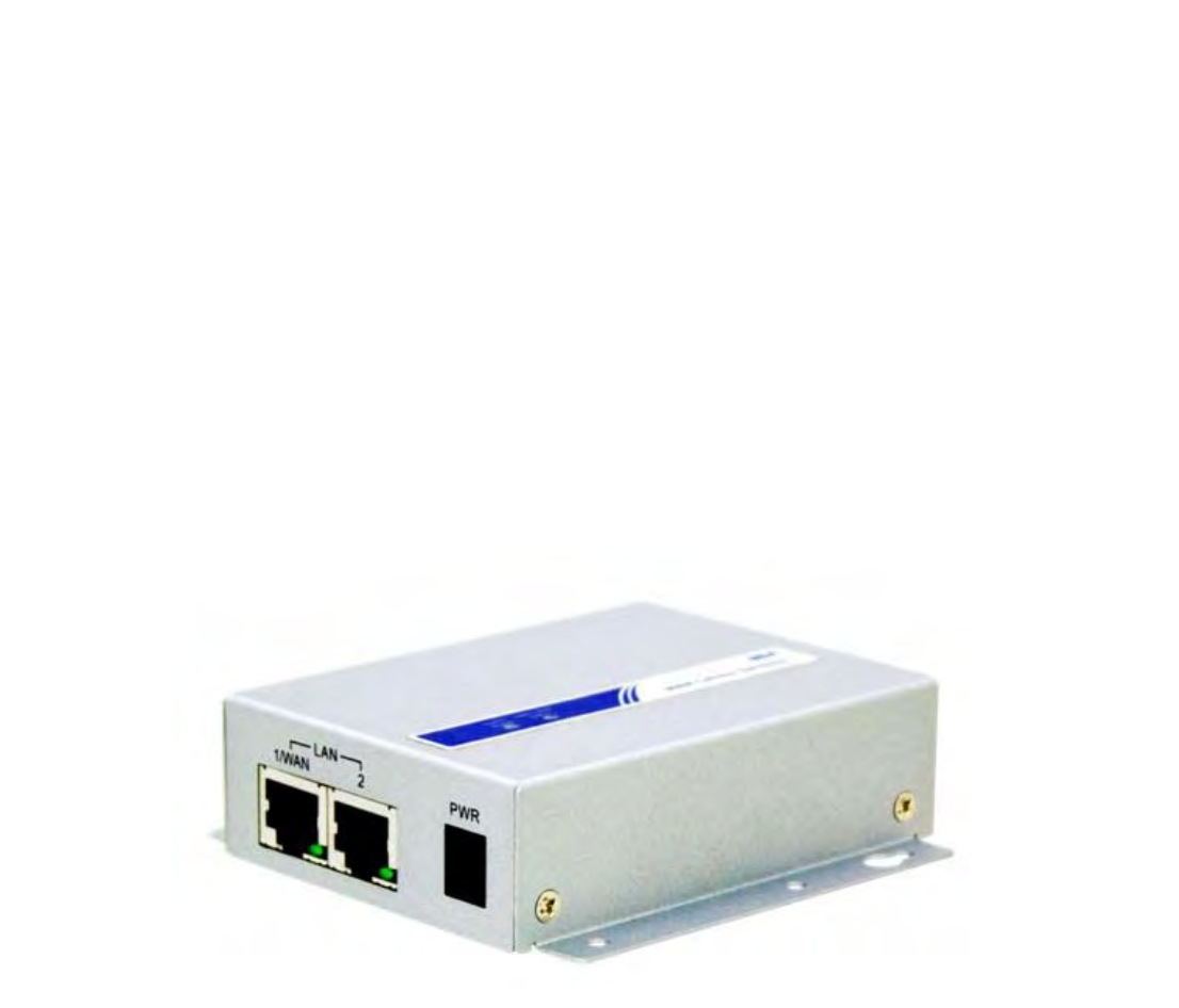
M2MCellularGateway
IDG500/IOG500(LTEcat.4)
UserManual

M2MCellularGateway
2
Chapter 1 Introduction ........................................................................................................................................... 6
1.1 Introduction .............................................................................................................................................. 6
1.2Contents List ............................................................................................................................................ 7
1.2.1 Package Contents ........................................................................................................................... 7
1.3 Hardware Configuration .......................................................................................................................... 8
1.4LED Indication ......................................................................................................................................... 9
1.5 Installation & Maintenance Notice ........................................................................................................ 10
1.5.1 SYSTEM REQUIREMENTS ..................................................................................................... 10
1.5.2 WARNING .................................................................................................................................. 10
1.5.3 HOT SURFACE CAUTION ....................................................................................................... 11
1.5.4 Product Information for CE RED Requirements ........................................................................ 12
1.6Hardware Installation ............................................................................................................................. 14
1.6.1 Mount the Unit ............................................................................................................................ 14
1.6.2 Insert the SIM Card ..................................................................................................................... 14
1.6.3 Install the External Antenna ........................................................................................................ 15
1.6.4 Connecting Power ....................................................................................................................... 16
1.6.5 Connecting to the Network or a Host ......................................................................................... 16
1.6.6 Setup by Configuring WEB UI .................................................................................................. 17
Chapter 2 Basic Network ..................................................................................................................................... 18
2.1WAN & Uplink ...................................................................................................................................... 18
2.1.1 Physical Interface ........................................................................................................................ 19
2.1.2 Internet Setup .............................................................................................................................. 24
2.2 LAN & VLAN ....................................................................................................................................... 43
2.2.1 Ethernet LAN ............................................................................................................................... 43
2.2.2 VLAN ......................................................................................................................................... 46
2.2.3 DHCP Server ............................................................................................................................... 57
2.3 WiFi (not supported) .............................................................................................................................. 65
2.4 IPv6 ........................................................................................................................................................ 66
2.4.1 IPv6 Configuration...................................................................................................................... 66
2.5 Port Forwarding .................................................................................................................................... 75
2.5.1 Configuration .............................................................................................................................. 76
2.5.2 Virtual Server & Virtual Computer ............................................................................................. 77

M2MCellularGateway
3
2.5.3 DMZ & Pass Through ................................................................................................................. 83
2.6 Routing ................................................................................................................................................... 86
2.6.1 Static Routing.............................................................................................................................. 87
2.6.2 Dynamic Routing ........................................................................................................................ 90
2.6.3 Routing Information .................................................................................................................... 95
2.7 DNS & DDNS ....................................................................................................................................... 96
2.7.1 DNS & DDNS Configuration ..................................................................................................... 96
Chapter 3 Object Definition ............................................................................................................................... 100
3.1 Scheduling............................................................................................................................................ 100
3.1.1 Scheduling Configuration ......................................................................................................... 100
3.2 User (not supported) ............................................................................................................................ 102
3.3 Grouping (not supported) ..................................................................................................................... 103
3.4 External Server..................................................................................................................................... 104
3.5Certificate ............................................................................................................................................. 107
3.5.1 Configuration (not supported)................................................................................................... 107
3.5.2 My Certificate ........................................................................................................................... 108
3.5.3 Trusted Certificate ..................................................................................................................... 115
Chapter 4 Field Communication (not supported) .............................................................................................. 121
Chapter 5 Security .............................................................................................................................................. 122
5.1VPN ...................................................................................................................................................... 122
5.1.1 IPSec ......................................................................................................................................... 123
5.1.2 OpenVPN .................................................................................................................................. 136
5.1.3 L2TP ......................................................................................................................................... 144
5.1.4 PPTP ......................................................................................................................................... 150
5.1.5 GRE........................................................................................................................................... 154
5.2 Firewall ................................................................................................................................................ 158
5.2.1 Packet Filter .............................................................................................................................. 158
5.2.2 URL Blocking ........................................................................................................................... 163
5.2.3 MAC Control ............................................................................................................................ 167
5.2.4 Content Filter (not supported) ................................................................................................... 170
5.2.5 Application Filter (not supported) ............................................................................................. 171
5.2.6 IPS ............................................................................................................................................. 172

M2MCellularGateway
4
5.2.7 Options ...................................................................................................................................... 176
Chapter 6 Administration ................................................................................................................................... 180
6.1 Configure & Manage ........................................................................................................................... 180
6.1.1 Command Script ....................................................................................................................... 181
6.1.2 TR-069 ...................................................................................................................................... 185
6.1.3 SNMP ........................................................................................................................................ 190
6.1.4 Telnet & SSH ............................................................................................................................ 201
6.2 System Operation ................................................................................................................................. 205
6.2.1 Password & MMI ...................................................................................................................... 205
6.2.2 System Information ................................................................................................................... 208
6.2.3 System Time.............................................................................................................................. 209
6.2.4 System Log ............................................................................................................................... 211
6.2.5 Backup & Restore ..................................................................................................................... 215
6.2.6 Reboot & Reset ........................................................................................................................ 216
6.3 FTP (not supported) ............................................................................................................................. 217
6.4 Diagnostic ............................................................................................................................................ 218
6.4.1 Diagnostic Tools ....................................................................................................................... 218
Chapter 7 Service ............................................................................................................................................... 219
7.1Cellular Toolkit .................................................................................................................................... 219
7.1.1 Data Usage ................................................................................................................................ 220
7.1.2 SMS........................................................................................................................................... 223
7.1.3 SIM PIN .................................................................................................................................... 226
7.1.4 USSD ........................................................................................................................................ 230
7.1.5 Network Scan ............................................................................................................................ 233
Chapter 8 Status ................................................................................................................................................. 235
8.1 Dashboard (not supported) ................................................................................................................... 235
8.2 Basic Network ...................................................................................................................................... 236
8.2.1 WAN & Uplink Status .............................................................................................................. 236
8.2.2 LAN & VLAN Status ............................................................................................................... 240
8.2.3 WiFi Status (not supported) ...................................................................................................... 241
8.2.4 DDNS Status ............................................................................................................................. 242
8.3 Security ................................................................................................................................................ 243

M2MCellularGateway
5
8.3.1 VPN Status ................................................................................................................................ 243
8.3.2 Firewall Status .......................................................................................................................... 247
8.4 Administration...................................................................................................................................... 251
8.4.1 Configure & Manage Status...................................................................................................... 251
8.5 Statistics & Report ............................................................................................................................... 253
8.5.1 Connection Session ................................................................................................................... 253
8.5.2 Network Traffic (not supported) ............................................................................................... 254
8.5.3 Device Administration .............................................................................................................. 255
8.5.4 Cellular Usage ........................................................................................................................... 256
Appendix A GPL WRITTEN OFFER................................................................................................................ 257

M2MCellularGateway
6
Chapter1Introduction
1.1Introduction
Congratulationsonyourpurchaseofthisoutstandingproduct:M2MCellularGateway.ForM2M(Machine‐to‐
Machine) applications, AMIT M2M Cellular Gateway is absolutely the right choice. With built‐in world‐class
3G/4Gmodule,youjustneedtoinsertSIMcardfromlocalmobilecarriertogettoInternet.ByVPNtunneling
technology,remotesiteseasilybecomeapartofIntranet,andalldataaretransmittedinasecure(256‐bitAES
encryption)link.
MainFeatures:
Compactdesign:Built‐inLTEandconfigurableEthernetWAN/LANcanprovideEthernetmachineeasy
connectiontointernet/intranetbyLTEorhighreliablefail‐overwired/LTEconnection.
Dual SIM: Embedded 3G/4G with configurable dual‐SIM achieve location freemulti‐ISPfail‐over
requirement.
VersatileCellular:Preferredserviceselectioncansimplifyuplinksetting;toolkitfunctionofdatausage
cancontrolbudget;configurableSMScommandisusefulandefficientforremoteadministration.
CompleteNetwork:Built‐inNAT/PortForward/Routing/IPv6arecompatibletoexistingIPnetwork.
HighlySecurity:VariousVPNprotocol&scenariocansetupsecureintranet;built‐inFirewallprevents
maliciousattacks;ACL&AuthenticationbyMAC/Userenhancessecureaccess.
FlexibleAdministration:WebUIisusedforbasicsetting;programmableCLIandCommandScriptare
usedforadvancedconfiguration;systemcanbemanagedbyNMSbasedonTR‐069.
SmartEventHanding:Mechanismtomanageactionforpre‐definedeventsbyadministrator.Events
canbetriggeredornotifiedbasedonSystem/Interfacestatuschange,SMS,SNMPtrap,ore‐mail.
Beforeyouinstallandusethisproduct,pleasereadthismanualindetailforfullyexploitingthefunctionsof
thisproduct.
M2MCellularGateway
7
1.2 ContentsList
1.2.1PackageContents
#StandardPackage
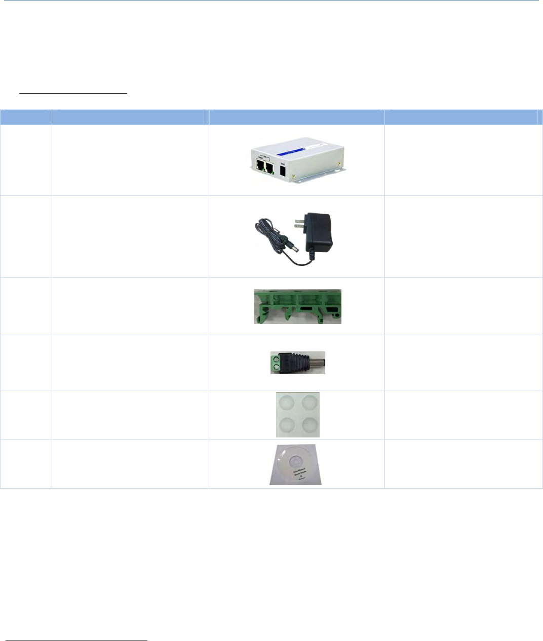
Items Description Contents Quantity
1 IDG500
M2MCellularGateway
1pcs
2
PowerAdapter
(DC5V/2A)
(*1)
1pcs
3 DIN‐RailBracket
1set(2pcs)
4 MaleDCJacktoScrewTerminal
BlockAdaptor 1pcs
5 RubberFeet 4pcs
6 CD
(Manual) 1pcs
1 The maximum power consumption of IDG500 series product is 7.0W.
M2MCellularGateway
8
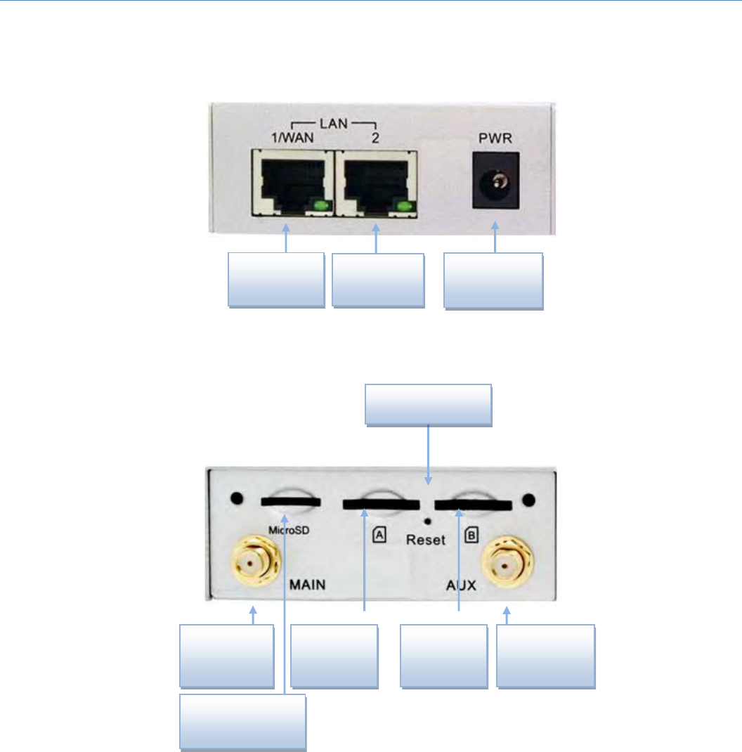
1.3HardwareConfiguration
LeftView
RightView
※ResetButton
TheRESETbuttonprovidesuserwithaquickandeasywaytoresortthedefaultsetting.PresstheRESETbutton
continuouslyfor6seconds,andthenreleaseit.Thedevicewillrestoretofactorydefaultsettings.
DCPower
Receptacle
LAN2
LAN1/
WAN
3G/4G
Antenna
3G/4G
Antenna
SIM-A SIM-B
Reset Button
MicroSD

M2MCellularGateway
9
1.4 LEDIndication
Indication LED
Color Description
Signal
LTE/3G
Blue
Purple
Red
WhentheLEDcolorisshownin:
Blue:CellularmoduleisinLTEMode.
Purple:CellularmoduleisinHSPA/3GMode.
Red:CellularmoduleisinGSM/2GMode.
WhenthebehaviorofLEDis:
FastFlash(per0.5second):SignalStrengthis0~30%
Flash(Slow,persecond):SignalStrengthis31~60%
SteadyOn:SignalStrengthis61~100%
Status Blue
Flash(persecond):Thegateway works normally.
Flash(Fast):ThegatewayisinRecoveryModeorabnormalsituation.
Note:Ifyouencounteredtheabnormalsituation,evenpowerOFF/ONthedevice,theremightbe
somethingwrongduringthedevicebootupsessionanditwasdamaged.YouneedtocallforRMA
servicetorecoverit.
LAN/WAN Green
Off:Hostdisconnected.
On:Ethernetconnectionestablished.
Flash:DatapackettransferredviaEthernet.
M2MCellularGateway
10
1.5Installation&MaintenanceNotice
1.5.1SYSTEMREQUIREMENTS
Network Requirements
AfastEthernetRJ45cable
3G/4Gcellularservicesubscription
10/100EthernetadapteronPC
Web-based Configuration Utility
Requirements
Computerwiththefollowing:
Windows®,Macintosh,orLinux‐basedoperating
system
AninstalledEthernetadapter
BrowserRequirements:
InternetExplorer6.0orhigher
Chrome2.0orhigher
Firefox3.0orhigher
Safari3.0orhigher
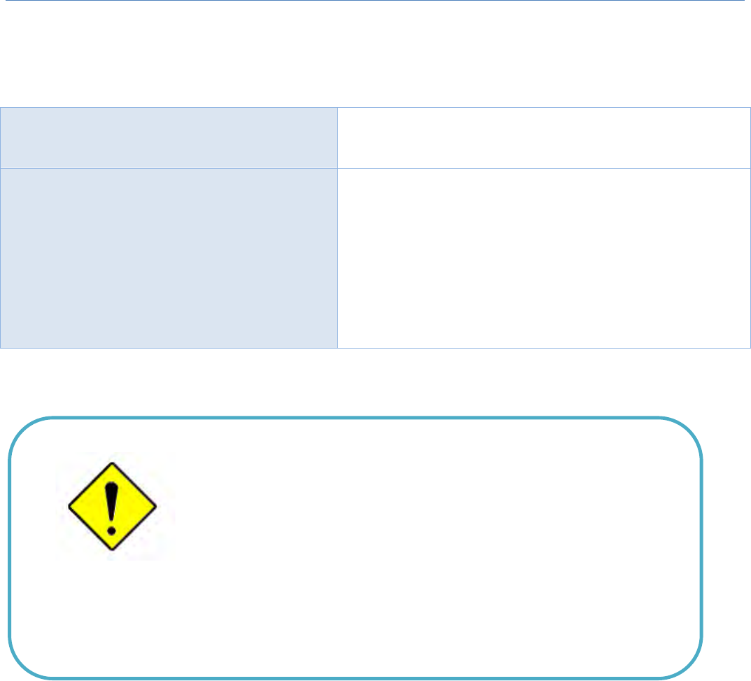
1.5.2WARNING
Only use the power adapter that comes with the
package. Using a different voltage rating power
adaptor is dangerous and may damage the product.
Do not open or repair the case yourself. If the
product is too hot, turn off the power immediately
and have it repaired at a qualified service center.
Place the product on a stable surface and avoid
using this product and all accessories outdoors.
Attention
M2MCellularGateway
11
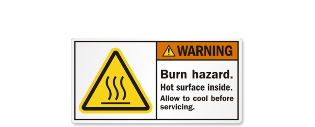
1.5.3HOTSURFACECAUTION
CAUTION:Thesurfacetemperatureforthemetallicenclosurecanbeveryhigh!
Especiallyafteroperatingforalongtime,installedataclosedcabinet
withoutairconditioningsupport,orinahighambienttemperature
space.
DONOTtouchthehotsurfacewithyourfingerswhileservicing!!

M2MCellularGateway
12
1.5.4ProductInformationforCEREDRequirements
ThefollowingproductinformationisrequiredtobepresentedinproductUserManualforlatestCERED
requirements.2
(1) FrequencyBand&MaximumPower
1.aFrequencyBandforCellularConnection(forME3630E1Cversion)3
Bandnumber OperatingFrequency Maxoutputpower
LTEFDDBAND1 Uplink:1920‐1980MHz
Downlink:2110‐2170MHz
23±2.7dBm
LTEFDDBAND3 Uplink:1710‐1785MHz
Downlink:1805‐1880MHz
LTEFDDBAND7 Uplink:2500‐2570MHz
Downlink:2620‐2690MHz
LTEFDDBAND8 Uplink:880‐915MHz
Downlink:925‐960MHz
LTEFDDBAND20 Uplink:832‐862MHz
Downlink:791‐821MHz
WCDMABAND1 Uplink:1920‐1980MHz
Downlink:2110‐2170MHz 24+1/‐3dBm
WCDMABAND8 Uplink:880‐915MHz
Downlink:925‐960MHz
E‐GSM Uplink:880‐915MHz
Downlink:925‐960MHz 33±2dBm
DCS Uplink:1710‐1785MHz
Downlink:1805‐1880MHz 30±2dBm
1.bFrequencyBandforCellularConnection(forEC25‐Eversion)
Bandnumber OperatingFrequency Maxoutputpower
LTEFDDBAND1 Uplink:1920‐1980MHz
Downlink:2110‐2170MHz 23.1dBm
LTEFDDBAND3 Uplink:1710‐1785MHz
Downlink:1805‐1880MHz 23.0dBm
LTEFDDBAND7 Uplink:2500‐2570MHz
Downlink:2620‐2690MHz 22.8dBm
LTEFDDBAND8 Uplink:880‐915MHz
Downlink:925‐960MHz 23.2dBm
LTEFDDBAND20 Uplink:832‐862MHz 23.5dBm
2TheinformationpresentedinthissectionisONLYvalidfortheEU/EFTAregionalversion.Forthosenon‐CE/EFTAversions,please
refertothecorrespondingproductspecification.
3TherecanbedifferentcellularmoduleintrgratedinthedeviceforEU/EFTAregionalversion.Refertothecellularmoduleidentifier
printedonthedevicelabelforthepurchaseddevice.

M2MCellularGateway
13
Downlink:791‐821MHz
LTEFDDBAND38 Uplink:2570‐2620MHz
Downlink:2570‐2620MHz 21.7dBm
LTEFDDBAND40 Uplink:2300‐2400MHz
Downlink:2300‐2400MHz 21.5dBm
WCDMABAND1 Uplink:1920‐1980MHz
Downlink:2110‐2170MHz 23.3dBm
WCDMABAND8 Uplink:880‐915MHz
Downlink:925‐960MHz
E‐GSM Uplink:880‐915MHz
Downlink:925‐960MHz 32.9dBm
DCS Uplink:1710‐1785MHz
Downlink:1805‐1880MHz 29.9dBm
1.cFrequencyBandforCellularConnection(forUC20‐Gversion)
Bandnumber OperatingFrequency Maxoutputpower
WCDMABAND1 Uplink:1922.4‐1977.6MHz
Downlink:2112.4‐2167.6MHz 22.47dBm
WCDMABAND8 Uplink:882.4‐912.6 MHz
Downlink:927.4‐957.6MHz 22.48dBm
E‐GSM Uplink:880.2‐914.8MHz
Downlink:925.2‐959.8MHz 32.1dBm
DCS Uplink:1710.2‐1784.8MHz
Downlink:1805.2‐1879.8MHz 28.9dBm
(2) DoCInformation
YoucangettheDoCinformationofthisproductfromthefollowingURL:
http://www.amit.com.tw/products‐doc/
(3) RFExposureStatements
Theantennaoftheproduct,undernormalusecondition,isatleast20cmawayfromthebodyofuser.

M2MCellularGateway
14
1.6 HardwareInstallation
Thischapterdescribeshowtoinstallandconfigurethehardware
1.6.1MounttheUnit
TheIDG500seriescanbeplacedonadesktop,ormountedonthewall.
1.6.2InserttheSIMCard
WARNING: BEFORE INSERTING OR CHANGING THE SIM CARD, PLEASE MAKESURE
THATPOWEROFTHEDEVICEISSWITCHEDOFF.
TheSIMcardslotsarelocatedattherightsideofIDG500 serieshousinginordertoprotecttheSIMcard.You
need to unscrew and remove the outer SIM card cover before installing or removing the SIM card. Please
followtheinstructionstoinsertorejectaSIMcard.AfterSIMcardiswellplaced,screwbacktheouterSIM
cardcover.
Step1:
Loosenthescrewsand
removetheSIMcover.
Step2:
PushtheSIMcard
intotheslotA(SIM‐
A)orslotB(SIM‐B).
Step3:
PushtheinsertedSIMcard
againtoejectitfromthe
SIMslot.

M2MCellularGateway
15
1.6.3InstalltheExternalAntenna
AsillustratedinSection1.3,thereareseveralSMAantennaJacksforyoutoinstalltherequiredantennasfor
theRFsignaltransmissionandreceiving.YouhavetopurchaserequiredRFcablesandantennasseparatelyfor
aspecificprojectorinstallationsitetogetexcellentRFperformance.
SincethereislimitedspacingforallocatingallSMAantennaJacksaroundtheenclosure,theseparationamong
SMA Jacks (or direct‐attached antennas) could be not the optimized arrangement. It is very likely to get
degradedRFperformanceatspecificcircumstances.Itdependsheavilyontheenvironment.
However,therearewell‐knownrulesofthumbforsolvingtheantennaseparationissue.
1:Thehorizontaldistancebetweenantennasshouldbegreaterthan1/4ofitswavelength,andtherewillbe
bestseparationat1/2ofitswavelength.
2. If multiple frequency antennas are near each other, then use spacing distance of the lower frequency
antenna,orevenbettertrytosatisfytheruleforbothfrequencies.
WavelengthTableforMajorRFCategory
RFCategory Frequency Wavelength 1/2WaveLength
(BestSeparation)
1/4WaveLength
(GoodSeparation)
CelllularLTE 2600MHz 11.5cm 5.8cm 2.9cm
CellularLTE 2100MHz 14.3cm 7.1cm 3.7cm
CellularLTE 900MHz 33.3cm 16.6cm 8.3cm
CellularLTE 700MHz 42.8cm 21.4cm 10.7cm
So,itisrecommendedtousesomeexternalRFcablestoextendandseparatetheadjacentantennasandget
betterantennaseparationandRFperformance.

M2MCellularGateway
16
1.6.4ConnectingPower
There are a DC5V/2A power adapter4anda2‐pinTerminalBlockadapterinthepackageforyoutoeasily
connectDCpowertothisgateway.
IfyoupoweredthegatewaywithotherDCPowerSource,PleasemakesuretheDCPowervoltageiscomplyto
5V~18V,andtheelectrodeshavebeenpluggedintotherightpinsaccordingtotheirassignments(‘+’forthe
DCPowerand‘‐‘fortheGNDwire).
WARNNING:Thiscommercial‐gradepoweradapterismainlyforeaseofpoweringup
the purchased device while initial configuration. It’s not for operating at wide
temperaturerangeenvironment.PLEASEPREPAREORPURCHASEOTHERINDUSTRIAL‐
GRADEPOWERSUPPLYFORPOWERINGUPTHEDEVICE.
1.6.5ConnectingtotheNetworkoraHost
TheIDG500 seriesproductprovides oneRJ45 port toconnect 10/100Mbps Ethernet. It can auto detect the
transmissionspeedonthenetworkandconfigureitselfautomatically.ConnectoneEthernetcabletotheRJ45
port(LAN)ofthedeviceandpluganotherendoftheEthernetcableintoyourcomputer’snetworkport.Inthis
way,youcanusetheRJ45EthernetcabletoconnectthedevicetothehostPC’sEthernetportforconfiguring
thedevice.
4 The maximum power consumption of IDG500 series product is 7.0W.
M2MCellularGateway
17
1.6.6SetupbyConfiguringWEBUI
YoucanbrowsewebUItoconfigurethedevice.
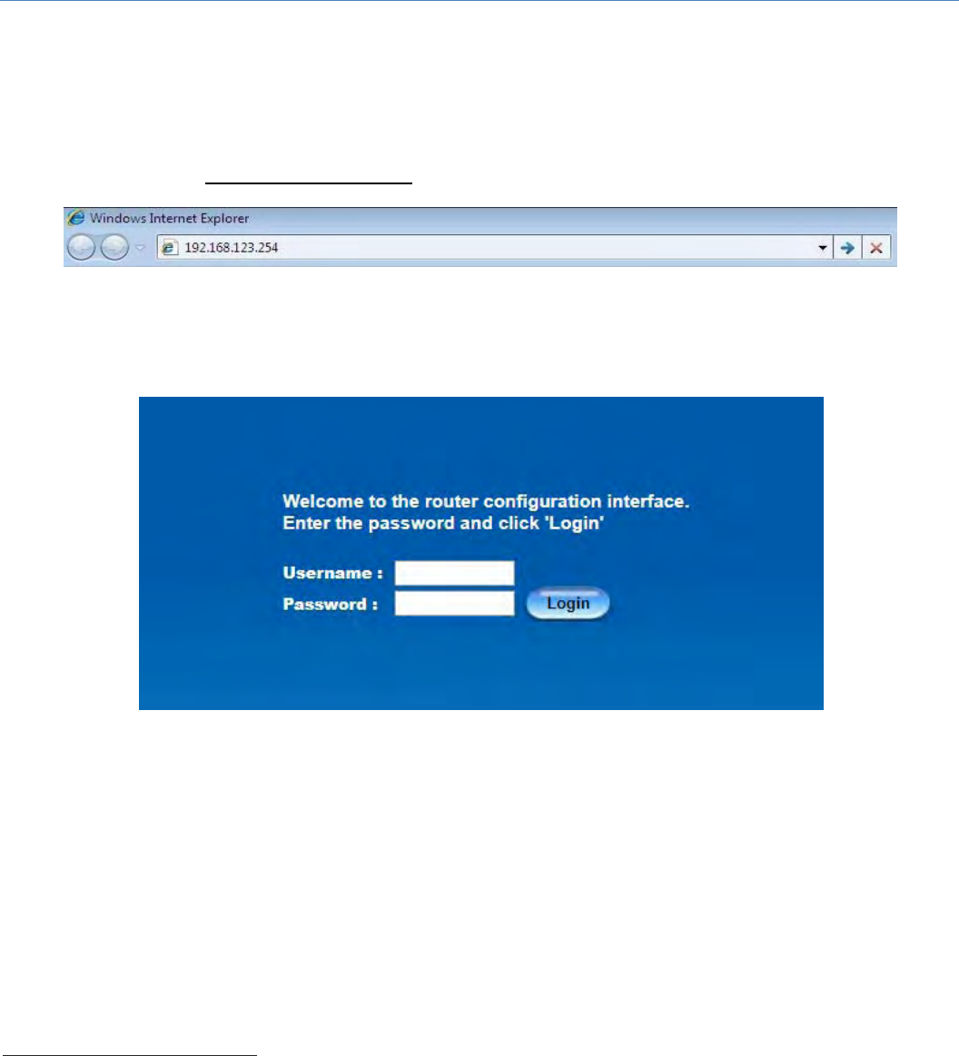
TypeintheIPAddress(http://192.168.123.254)5
Whenyouseetheloginpage,entertheusernameandpasswordandthenclick‘Login’button.
Thedefaultsettingforbothusernameandpasswordis‘admin’6.
5ThedefaultLANIPaddressofthisgatewayis192.168.123.254.Ifyouchangeit,youneedtologinbyusing
thenewIPaddress.
6Forsecurityconsideration,youarestronglyrecommendedtochangetheloginusernameandpasswordfrom
defaultvalues.RefertoSection6.1.2forhowtochangethesetting.
M2MCellularGateway
18
Chapter2BasicNetwork
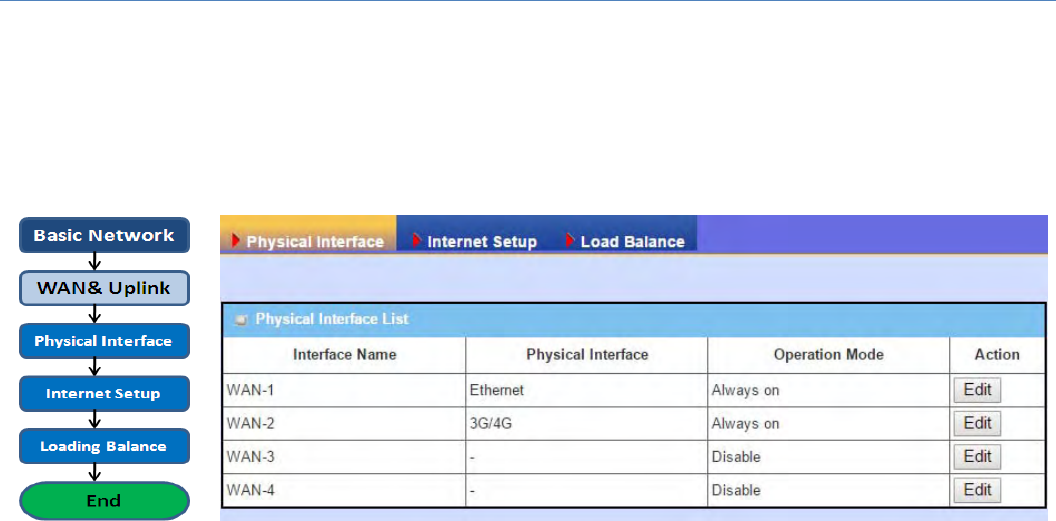
2.1 WAN&Uplink
The gateway provides multiple WAN interfaces to let all client hostsinIntranetofthegatewayaccessthe
InternetviaISP.ButISPsintheworldapplyvariousconnectionprotocolstoletgatewaysoruser'sdevicesdial
inISPsandthenlinktotheInternetviadifferentkindsoftransmitmedia.
So, the WAN Connection lets you specify the WAN Physical Interface, WAN Internet Setup and WAN Load
BalanceforIntranettoaccessInternet.ForeachWANinterface,youmustspecifyitsphysicalinterfacefirst
andthenitsInternetsetuptoconnecttoISP.Besides,sincethegatewayhasmultipleWANinterfaces,youcan
assignphysicalinterfacetoparticipateintheLoadBalancefunction.
M2MCellularGateway
19
2.1.1PhysicalInterface
M2MgatewaysareusuallyequippedwithvariousWANinterfacessto support different WAN connection
scenarioforrequirement.YoucanconfiguretheWANinterfaceonebyonetogetproperinternetconnection
setup.RefertotheproductspecificationfortheavailableWANinterfacesintheproductyoupurchased.
ThefirststeptoconfigureoneWANinterfaceistospecifywhichkindofconnectionmediatobeusedforthe
WANconnection,asshownin"PhysicalInterface"page.
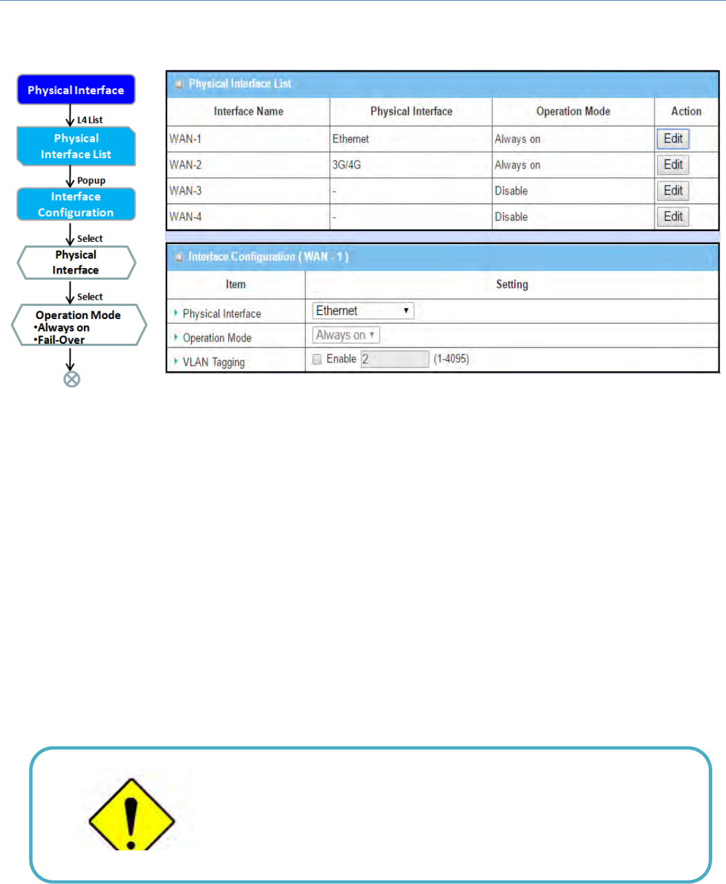
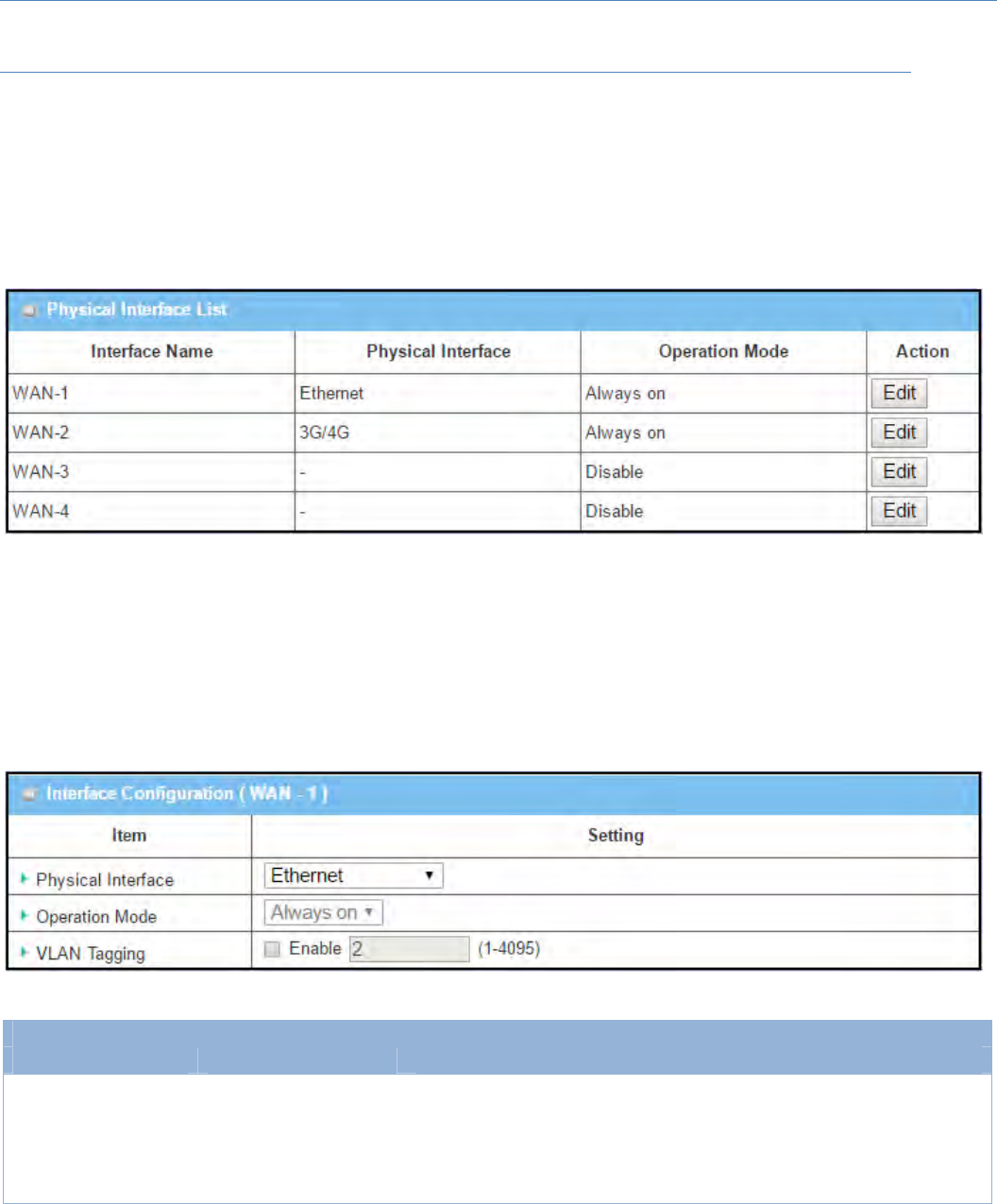
In "Physical Interface" page, there are two configuration windows, "Physical Interface List" and "Interface
Configuration"."Physical Interface List" window shows allthe available physical interfaces. After clicking on
the"Edit"buttonfor theinterfacein"PhysicalInterface List" windowthe"Interface Configuration"window
willappeartoletyouconfigureaWANinterface.
PhysicalInterface:
• Ethernet WAN: The gateway has one or more RJ45 WAN ports that can be configured to be WAN
connections.YoucandirectlyconnecttoexternalDSLmodemorsetupbehindafirewalldevice.
• 3G/4G WAN: The gateway has one built‐in 3G/4G cellular as WAN connection. For each cellular WAN,
thereare1or2SIMcardstobeinsertedforspecialfailoverfunction.
Please MUST POWER OFF the gateway before you
insert or remove SIM card.
The SIM card can be damaged if you insert or
remove SIM card while the gateway is in operation.
M2MCellularGateway
20
OperationMode:
Therearethreeoptionitems“Alwayson”,“Failover”,and“Disable”fortheoperationmodesetting.
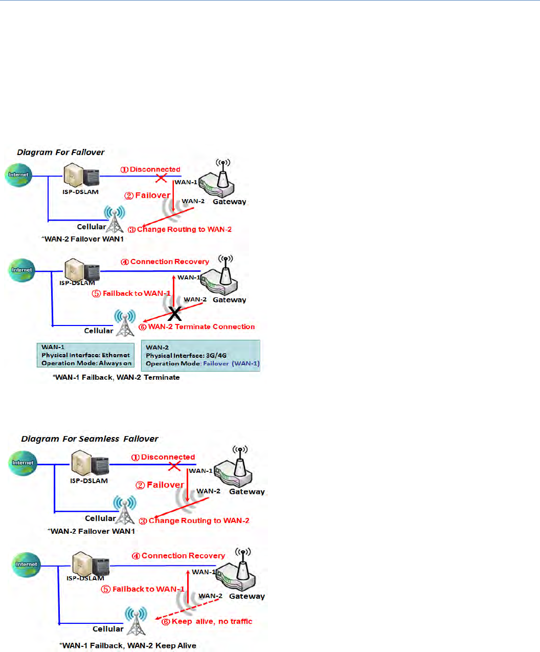
Always on: SetthisWANinterfacetobeactiveallthetime.Whentwoormore WAN are established at
"Alwayson"mode,outgoingdatawillthroughtheseWANconnectionsbaseonloadbalancepolicies.
Failover:
A failover interface is a backup connection to the
primary. That means only when its primary WAN
connection is broken, the backup connection will be
starteduptosubstitutetheprimaryconnection.
Asshowninthediagram,WAN‐2isbackupWANfor
WAN‐1.WAN‐1servesastheprimaryconnectionwith
operationmode"Alwayson".WAN‐2won’tbe
activated until WAN‐1 disconnected. When WAN‐1
connectionisrecoveredbackwithaconnection,itwill
take over data traffic again. At that time, WAN‐2
connectionwillbeterminated.
SeamlessFailover:
Inaddition,thereisa"Seamless"optionforFailover
operationmode. When seamless optionisactivated
bycheckingonthe"Seamless"boxinconfiguration
window, both the primary connection and the
failover connection are started up after system
rebooting.Butonlytheprimaryconnectionexecutes
the data transfer, while the failover one just keeps
alive of connection line. As soon as the primary
connection is broken, the system will switch,
meaning failover, the routing path to the failover
connection to save the dial up time of failover
connectionsinceithasbeenalive.
Whenthe“Seamless”enablecheckboxisactivated,it
can allow the Failover interface to be connected
continuouslyfromsystembootingup.FailoverWAN
interface just keeps connecting without data traffic.

M2MCellularGateway
21
Thepurposeistoshortentheswitchtimeduringfailoverprocess. So, when primary connection is
disconnected,failoverinterfacewilltakeoverthedatatransfermissioninstantlybyonlychangingrouting
path to the failover interface. The dialing‐up time of failover connection is saved since it has been
connectedbeforehand.
VLANTagging
Sometimes,yourISPrequiredaVLANtagtobeinsertedintotheWANpacketsfromGatewayforspecific
services.PleaseenableVLANtaggingandspecifytagintheWANphysicalinterface.Pleasebenotedthatonly
EthernetandADSLphysicalinterfacessupportthefeature.Forthedevicewith3G/4GWANonly,itisdisabled.
M2MCellularGateway
22
PhysicalInterfaceSetting
GotoBasicNetwork>WAN>PhysicalInterfacetab.
ThePhysicalInterfaceallowsusertosetupthephysicalWANinterfaceandtoadjustWAN’sbehavior.
Note:NumbersofavailableWANInterfacescanbedifferentforthepurchasedgateway.
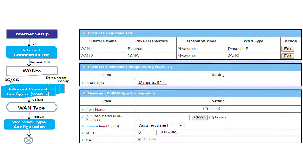
When Edit button is applied, an Interface Configuration screen will appear. WAN‐1 interface is used in this
example.
InterfaceConfiguration:
InterfaceConfiguration
Item Valuesetting Description
PhysicalInterface
1.AMustfillsetting
2.WAN‐1istheprimary
interfaceandisfactory
settoAlwayson.
Selectoneexpectedinterfacefromtheavailableinterfacedropdownlist.It
canbe3G/4GorEtherent.
Dependingonthegatewaymodel,DisableandFailoveroptionswillbe
availableonlytomultipleWANgateways.WAN‐2~WAN‐4interfacesare
onlyavailabletomultipleWANgateway.

M2MCellularGateway
23
OperationMode AMustfillsetting
Definetheoperationmodeoftheinterface.
SelectAlwaysontomakethisWANalwaysactive.
SelectDisabletodisablethisWANinterface.
SelectFailovertomakethisWANaFailoverWANwhentheprimaryorthe
secondaryWANlinkfailed.Thenselecttheprimaryortheexisted
secondaryWANinterfacetoswitchFailoverfrom.
(Note:forWAN‐1,onlyAlwaysonoptionisavailable.)
VLANTagging Optionalsetting
CheckEnableboxtoentertagvalueprovidedbyyourISP.Otherwise
uncheckthebox.
ValueRange:1~4095.
Note:ThisfeatureisNOTavailablefor3G/4GWANconnection.
M2MCellularGateway
24
2.1.2InternetSetup
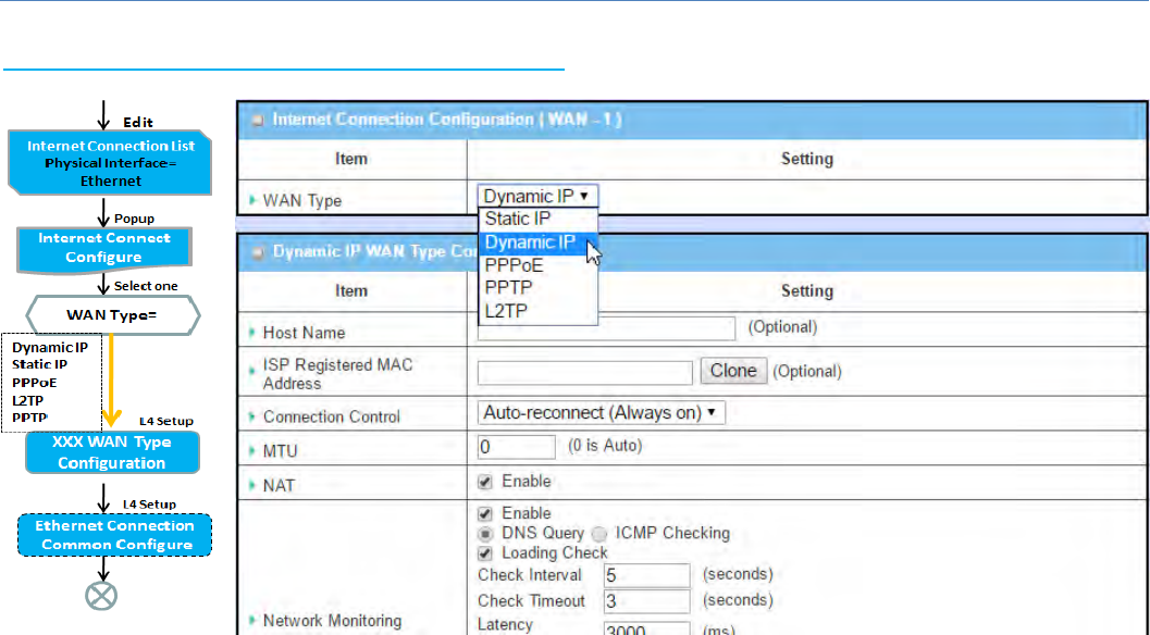
AfterspecifyingthephysicalinterfaceforeachWANconnection, administrator must configure their
connectionprofiletomeetthedialinprocessofISP,sothatallclienthostsintheIntranetofthegatewaycan
accesstheInternet.
In"InternetSetup"page,therearesomeconfigurationwindows:"InternetConnectionList","Internet
ConnectionConfiguration","WANTypeConfiguration"andrelatedconfigurationwindowsforeachWANtype.
FortheInternetsetupofeach WAN interface,youmustspecifyitsWANtypeofphysicalinterfacefirstand
thenitsrelatedparameterconfigurationforthatWANtype.
After clicking on the "Edit" button of a physical interface in "Internet Setup List" window, the "Internet
ConnectionConfiguration"windowwillappeartoletyouspecifywhichkindofWANtypethatyouwillusefor
thatphysicalinterfacetomakeanInternetconnection.BasedonyourchosenWANtype,youcanconfigure
necessaryparametersineachcorrespondingconfigurationwindow.
M2MCellularGateway
25
InternetConnectionList‐EthernetWAN
WANTypeforEthernetInterface:
EthernetisthemostcommonWANanduplinkinterfaceforM2Mgateways.UsuallyitisconnectedwithxDSL
orcablemodemforyoutosetuptheWANconnection.TherearevariousWANtypestoconnectwithISP.
• StaticIP:SelectthisoptionifISPprovidesafixedIPtoyouwhenyousubsribetheservice.Usuallyismore
expensivebutveryimportatforcooperaterequirement.
• DynamicIP:TheassignedIPaddressfortheWANbyaDHCPserverisdifferenteverytime.Itischeaper
andusuallyforconsumeruse.
• PPPoverEthernet:AsknownasPPPoE.ThisWANtypeiswidelyusedforADSLconnection.IPisusually
differentforeverydialup.
• PPTP:ThisWANtypeispopularinsomecountries,likeRussia.
• L2TP:ThisWANtypeispopularinsomecountries,likeIsrael.
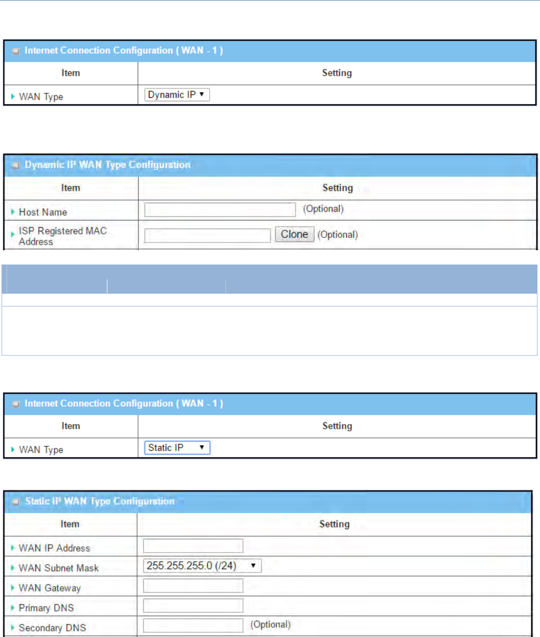
ConfigureEthernetWANSetting
WhenEditbuttonisapplied,InternetConnectionConfigurationscreenwillappear.WAN‐1interfaceisusedin
thisexample.
M2MCellularGateway
26
WANType=DynamicIP
Whenyouselectit,"DynamicIPWANTypeConfiguration"willappear.Itemsandsettingisexplainedbelow
DynamicIPWANTypeConfiguration
Item Valuesetting Description
HostName An optional setting Enterthehostnameprovidedbyyour ServiceProvider.
ISPRegisteredMAC
Address Anoptionalsetting
Enter theMACaddressthatyouhaveregisteredwithyourserviceprovider.
OrClicktheClonebuttontocloneyourPC’sMACtothisfield.
UsuallythisisthePC’sMACaddressassignedtoallowyoutoconnectto
Internet.
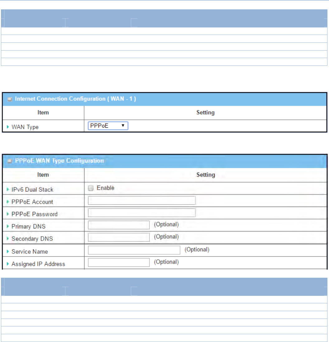
WANType=StaticIP
Whenyouselectit,"StaticIPWANTypeConfiguration"willappear.Itemsandsettingisexplainedbelow
M2MCellularGateway
27
StaticIPWANTypeConfiguration
Item Valuesetting Description
WANIPAddress AMustfilledsetting Enter theWANIPaddress givenbyyourServiceProvider
WANSubnetMask AMustfilledsetting Enter theWANsubnetmaskgivenbyyourServiceProvider
WANGateway AMustfilledsettingEnter theWANgatewayIPaddress givenbyyourServiceProvider
PrimaryDNS AMustfilledsetting Enter the primary WANDNSIPaddress givenbyyourServiceProvider
SecondaryDNS Anoptionalsetting Enter the secondary WANDNSIPaddress givenbyyourServiceProvider
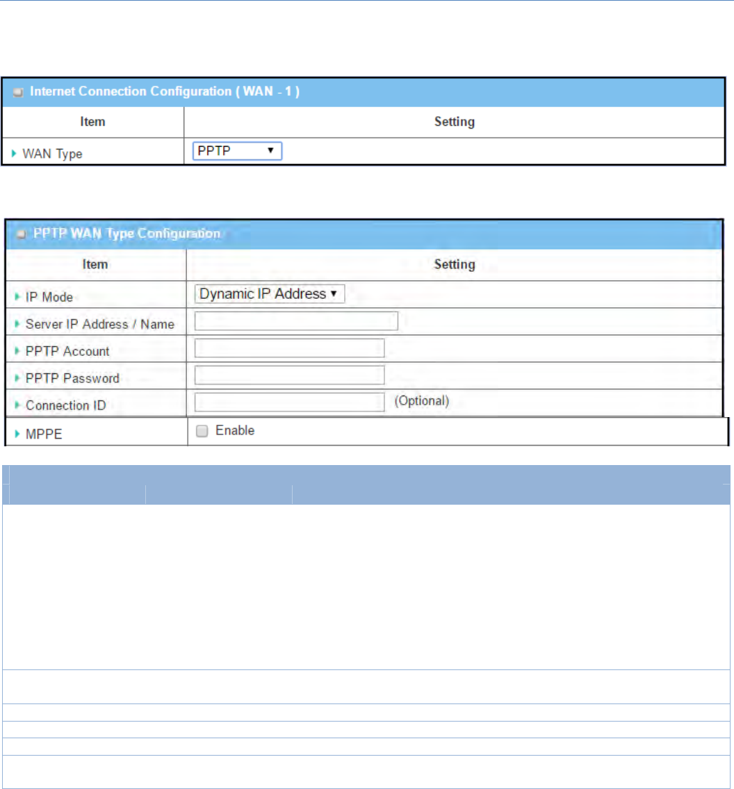
WANType=PPPoE
Whenyouselectit,"PPPoEWANTypeConfiguration"willappear.Itemsandsettingisexplainedbelow
PPPoEWANTypeConfiguration
Item Valuesetting Description
PPPoEAccount AMustfilledsetting Enter thePPPoEUserNameprovidedbyyourServiceProvider.
PPPoEPassword AMustfilledsetting Enter thePPPoEpassword providedbyyourServiceProvider.
PrimaryDNS Anoptionalsetting Enter theIPaddressofPrimaryDNSserver.
SecondaryDNS Anoptionalsetting Enter theIPaddressofSecondaryDNSserver.
ServiceName Anoptionalsetting EntertheservicenameifyourISPrequiresit
AssignedIPAddress Anoptionalsetting EntertheIPaddressassignedbyyourServiceProvider.
M2MCellularGateway
28
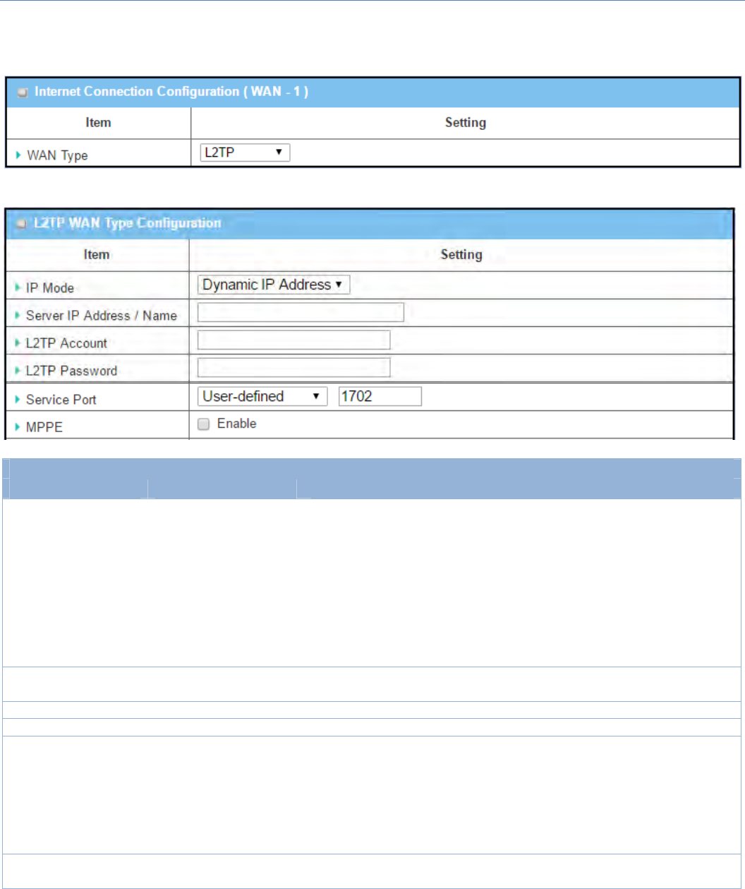
WANType=PPTP
Whenyouselectit,"PPTPWANTypeConfiguration"willappear.Itemsandsettingisexplainedbelow
PPTPWANTypeConfiguration
Item Valuesetting Description
IPMode A Must filled setting
SelecteitherStaticorDynamicIPaddressforPPTPInternetconnection.
WhenStaticIPAddressisselected,youwillneedtoentertheWANIP
Address,WANSubnetMask,andWANGateway.
WANIPAddress(AMustfilledsetting):EntertheWANIP
addressgivenbyyourServiceProvider.
WANSubnetMask(AMustfilledsetting):EntertheWAN
subnetmaskgivenbyyourServiceProvider.
WANGateway(AMustfilledsetting):EntertheWANgateway
IPaddressgivenbyyourServiceProvider.
WhenDynamicIPisselected,therearenoabovesettingsrequired.
ServerIP
Address/Name A Must filled setting EnterthePPTPservernameorIPAddress.
PPTPAccount AMustfilledsetting Enter thePPTP usernameprovidedbyyourServiceProvider.
PPTPPassword AMustfilledsetting Enter thePPTPconnectionpasswordprovidedbyyourServiceProvider.
ConnectionID Anoptionalsetting EnteranametoidentifythePPTPconnection.
MPPE Anoptionalsetting SelectEnabletoenableMPPE (MicrosoftPoint‐to‐PointEncryption)
securityforPPTPconnection.
M2MCellularGateway
29
WANType=L2TP
Whenyouselectit,"L2TPWANTypeConfiguration"willappear.Itemsandsettingisexplainedbelow
L2TPWANTypeConfiguration
Item Valuesetting Description
IPMode A Must filled setting
SelecteitherStaticorDynamicIPaddressforL2TPInternetconnection.
WhenStaticIPAddressisselected,youwillneedtoentertheWANIP
Address,WANSubnetMask,andWANGateway.
WANIPAddress(AMustfilledsetting):EntertheWANIP
addressgivenbyyourServiceProvider.
WANSubnetMask(AMustfilledsetting):EntertheWAN
subnetmaskgivenbyyourServiceProvider.
WANGateway(AMustfilledsetting):EntertheWANgateway
IPaddressgivenbyyourServiceProvider.
WhenDynamicIPisselected,therearenoabovesettingsrequired.
ServerIP
Address/Name A Must filled setting EntertheL2TP servernameorIPAddress.
L2TPAccount AMustfilledsetting Enter theL2TP usernameprovidedbyyourServiceProvider.
L2TPPassword AMustfilledsetting Enter theL2TP connectionpasswordprovidedbyyourServiceProvider.
ServicePort A Must filled setting
Enter theservice portthattheInternetservice.
Therearethreeoptionscanbeselected:
Auto:Portwillbeautomaticallyassigned.
1701(ForCisco):Setserviceporttoport1701toconnectto
CISCOserver.
User‐defined:enteraserviceportprovidedbyyourService
Provider.
MPPE Anoptionalsetting SelectEnabletoenableMPPE (MicrosoftPoint‐to‐PointEncryption)
securityforPPTPconnection.
M2MCellularGateway
30
EthernetConnectionCommonConfiguration
TherearesomeimportantparameterstobesetupnomatterwhichEthernetWANtypeisselected.Youshould
followuptheruletoconfigure.
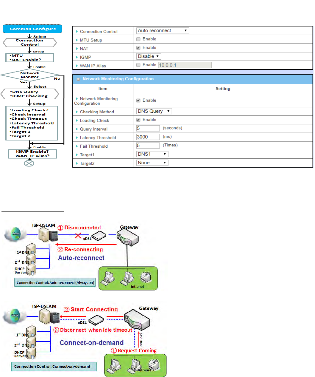
ConnectionControl.
Auto‐reconnect: This gateway will establish
Internet connection automatically once it has
been booted up, and try to reconnect once the
connectionisdown.It’srecommendedtochoose
this scheme if for mission critical applications to
ensurefull‐timeInternetconnection.
Connect‐on‐demand:Thisgatewaywon’tstartto
establish Internet connection until local data is
goingtobe sent to WAN side. Afternormaldata
transferringbetweenLANandWANsides,this
gateway will disconnect WAN connection if idle
timereachesvalueofMaximumIdleTime.
M2MCellularGateway
31
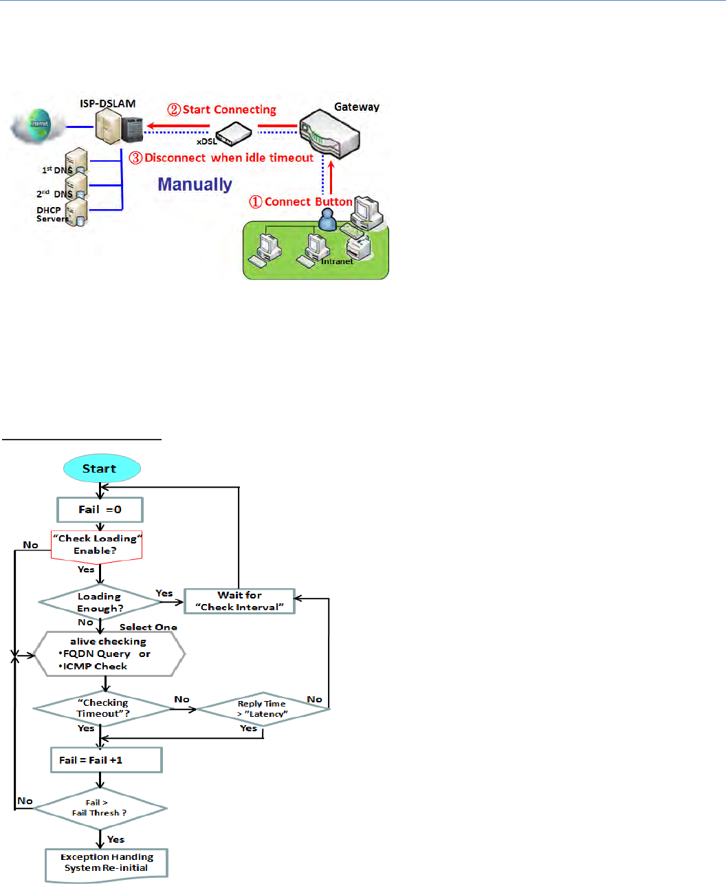
Manually: This gateway won’t start to establish
WAN connection until you press “Connect”
buttononwebUI.Afternormaldatatransferring
between LAN and WAN sides, this gateway will
disconnectWANconnectionifidletimereaches
valueofMaximumIdleTime.
Pleasebenoted,iftheWANinterfaceservesastheprimaryoneforanotherWANinterfaceinFailoverrole,
theConnectionControlparameterwillnotbeavailabletoyoutoconfigureasthesystemmustsetitto“Auto‐
reconnect(Alwayson)”.
NetworkMonitoring
It is necessary to monitor connection status continuous.
Todoit,"ICMPCheck"and"FQDNQuery"areusedto
check. When there is trafiic of connection, checking
packet will waste bandwidth. Response time of replied
packets may also increase. To avoid "Network
Monitoring" work abnormally, enabling "Checking
Loading"optionwillstopconnectioncheckwhenthereis
traffic. It will wait for another "Check Interval" and then
checkloadingagain.
Whenyoudo“NetworkMonitoring”,ifreplytimelonger
than "Latency" or even no response longer than
"CheckingTimeout","Fail"countwillbeincreased.Ifitis
continuousand"Fail"countismorethan"FailThreshold",
gateway will do exception handing process and re‐initial
this connection again . Otherwise, network monitoring
processwillbestartagain.

M2MCellularGateway
32
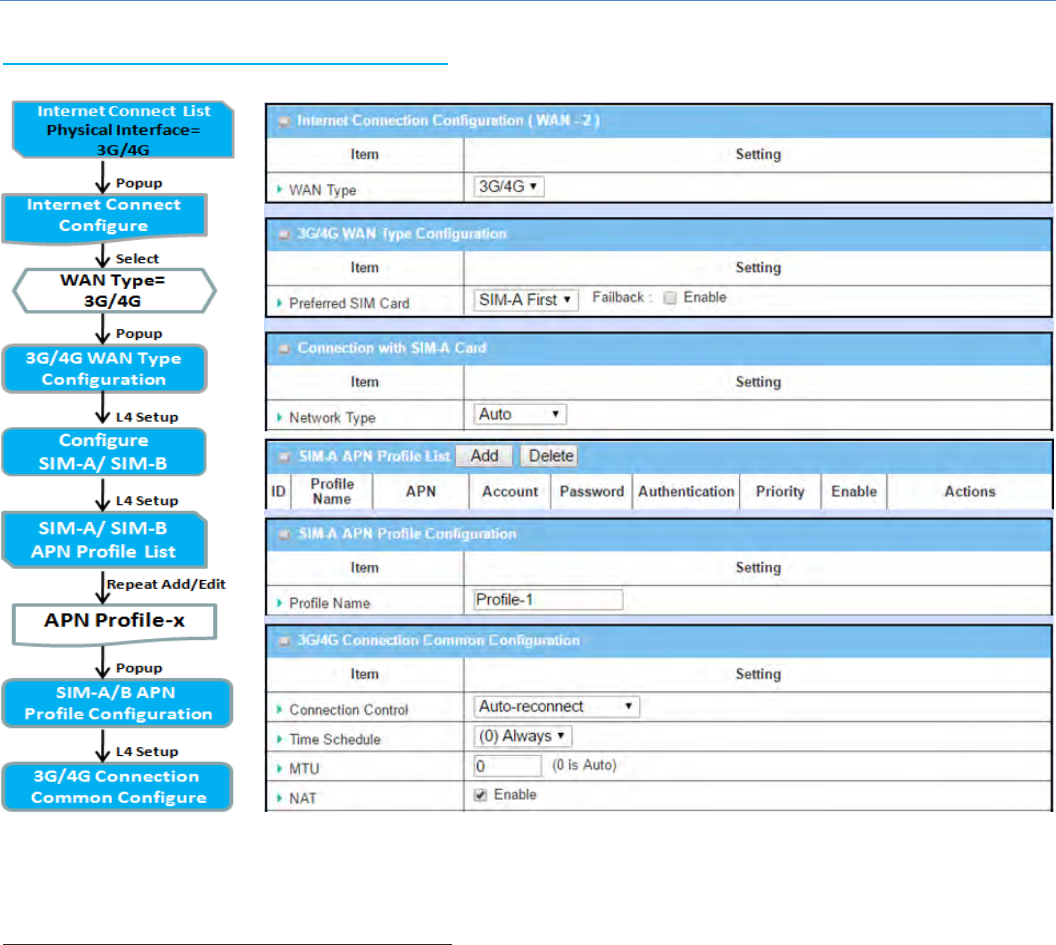
Setup“EthernetCommonConfiguration”
EthernetWANCommonConfiguration
Item Valuesetting Description
ConnectionControl AMustfilledsetting
Therearethree connection modes.
Auto‐reconnectenablestheroutertoalwayskeeptheInternet
connectionon.
Connect‐on‐demandenablestheroutertoautomaticallyre‐
establishInternetconnectionassoonasuserattemptstoaccess
theInternet.Internetconnectionwillbedisconnectedwhenithas
beeninactiveforaspecifiedidletime.
ConnectManuallyallowsusertoconnecttoInternetmanually.
Internetconnectionwillbeinactiveafterithasbeeninactivefor
specifiedidletime.
MaximumIdleTime
1.AnOptionalsetting
2.Bydefault600
secondsisfilled‐in
SpecifythemaximumIdletimesettingtodisconnecttheinternet
connectionwhentheconnectionidletimedout.
ValueRange:300~86400.
Note:ThisfieldisavailableonlywhenConnect‐on‐demandorConnect
Manuallyisselectedastheconnectioncontrolscheme.
MTUSetup 1.AnOptionalsetting
2.Uncheckbydefault
ChecktheEnableboxtoenabletheMTU(MaximumTransmissionUnit)
limit,andspecifytheMTUforthe3G/4Gconnection.
MTUreferstoMaximumTransmissionUnit.Itspecifiesthelargestpacket
sizepermittedforInternettransmission.
ValueRange:1200~1500.
MTUSetup
1. AMustfilledsetting
2. Auto(valuezero)is
setbydefault
3. Manualsetrange
1200~1500
MTUreferstoMaximumTransmissionUnit.Itspecifiesthelargestpacket
sizepermittedforInternettransmission.
WhensettoAuto(value‘0’),therouterselectsthebestMTUforbest
Internetconnectionperformance.
NAT
1. Anoptionalsetting
2. NATisenabledby
default
EnableNATtoapplyNATontheWANconnection.Unchecktheboxto
disableNATfunction.
NetworkMonitoring 1. Anoptionalsetting
2. Enabledbydefault
When theNetworkMonitoringfeatureisenabled,thegateway willuse
DNSQueryorICMPtoperiodicallycheckInternetconnection–connected
ordisconnected.
ChooseeitherDNSQueryorICMPCheckingtodetectWANlink.
WithDNSQuery,thesystemcheckstheconnectionbysendingDNS
QuerypacketstothedestinationspecifiedinTarget1andTarget2.
WithICMPChecking,thesystemwillcheckconnectionbysending
ICMPrequestpacketstothedestinationspecifiedinTarget1and
Target2.
LoadingCheck
EnableLoadingCheckallowstheroutertoignoreunreturnedDNS
QueriesorICMPrequestswhenWANbandwidthisfullyoccupied.
Thisistopreventfalselink‐downstatus.
CheckIntervaldefinesthetransmittingintervalbetweentwoDNS
QueryorICMPcheckingpackets.
CheckTimeoutdefinesthetimeoutofeachDNSquery/ICMP.
LatencyThresholddefinesthetolerancethresholdofresponding
time.
FailThresholdspecifiesthedetecteddisconnectionbeforetherouter
recognizetheWANlinkdownstatus.Enteranumberofdetecting

M2MCellularGateway
33
disconnectiontimestobethe thresholdbeforedisconnection is
acknowledged.
Target1(DNS1setbydefault)specifiesthefirsttargetofsendingDNS
query/ICMPrequest.
DNS1:settheprimaryDNStobethetarget.
DNS2:setthesecondaryDNStobethetarget.
Gateway:settheCurrentgatewaytobethetarget.
OtherHost:enteranIPaddresstobethetarget.
Target2(Nonesetbydefault)specifiesthesecondtargetofsending
DNSquery/ICMPrequest.
None:todisableTarget2.
DNS1:settheprimaryDNStobethetarget.
DNS2:setthesecondaryDNStobethetarget.
Gateway:settheCurrentgatewaytobethetarget.
OtherHost:enteranIPaddresstobethetarget.
IGMP
1.AMustfilledsetting
2.Disableissetby
default
EnableIGMP(InternetGroupManagementProtocol)wouldenablethe
routertolistentoIGMPpacketstodiscoverwhichinterfacesareconnected
towhichdevice.Therouterusestheinterfaceinformationgeneratedby
IGMPtoreducebandwidthconsumptioninamulti‐accessnetwork
environmenttoavoidfloodingtheentirenetwork.
WANIPAlias 1.Anoptionalsetting
2.Uncheckbydefault
EnableWANIPAlias thenentertheIPaddressprovidedbyyourservice
provider.
WANIPAliasisusedbythedevicerouterandistreatedasasecondsetof
WANIPtoprovidedualWANIPaddresstoyourLANnetwork.
Save N/A ClickSave tosavethesettings.
Undo N/A ClickUndo tocancelthesettings.
M2MCellularGateway
34
InternetConnection–3G/4GWAN
PreferredSIMCard–DualSIMFailOver
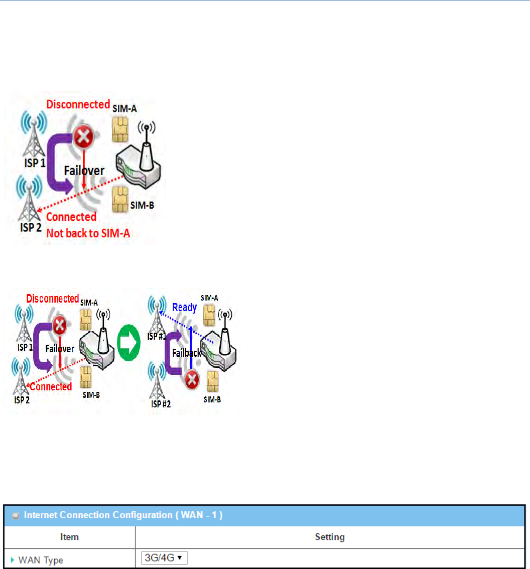
For3G/4Gembeddeddevice,oneembeddedcellularmodulecancreateonlyoneWANinterface.Thisdevice
hasfeaturedbyusingdualSIMcardsforonemodulewithspecialfail‐overmechanism.Itis calledDualSIM
Failover.ThisfeatureisusefulforISPswitchoverwhenlocationischanged.Within“DualSIMFailover”,there
arevarioususagescenarios,including"SIM‐AFirst","SIM‐BFirst“with“Failback”enabledornot,and“SIM‐A
Onlyand“SIM‐BOnly”.
M2MCellularGateway
35
SIM‐A/SIM‐Bonly:When“SIM‐AOnly”or“SIM‐BOnly”isused,thespecifiedSIMslotcardistheonlyoneto
beusedfornegotiationparametersbetweengatewaydeviceandcellularISP.
SIM‐A/SIM‐BfirstwithoutenableFailback
Bydefault,“SIM‐AFirst”scenarioisusedtoconnecttocellularISPfor
datatransfer.Inthecaseof“SIM‐AFirst”or“SIM‐BFirst”scenario, the
gatewaywilltrytoconnecttotheInternetbyusingSIM‐AorSIM‐Bcard
first.Andwhentheconnectionisbroken,thegatewaywillswitchtouse
theotherSIMcardforanalternateautomaticallyandwillnotswitchback
to use original SIM card except current SIM connection is also broken.
That is, SIM‐A and SIM‐B are used iteratively, but either one will keep
beingusedfordatatransferwhencurrentconnectionisstillalive.
SIM‐A/SIM‐BfirstwithFailbackenable
With Failback option enabled, “SIM‐A First” scenario is
usedtoconnectwhentheconnectionisbroken,gateway
system will switch to use SIM‐B. And when SIM‐A
connectionisrecovered,itwillswitchbacktouseoriginal
SIM‐Acard
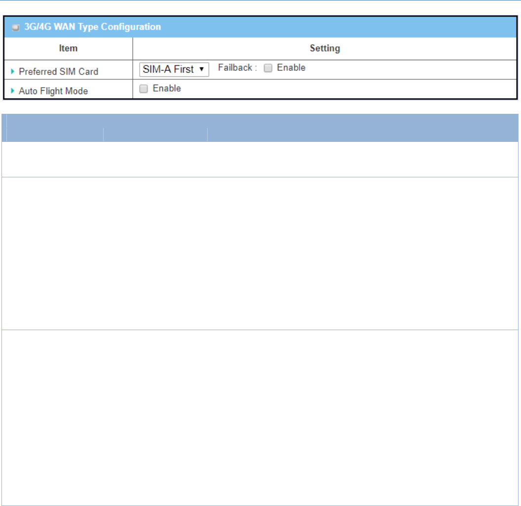
Configure3G/4GWANSetting
WhenEditbuttonisapplied,InternetConnectionConfiguration,and3G/4GWANConfigurationscreenswill
appear.
M2MCellularGateway
36
3G/4GConnectionConfiguration
Item Valuesetting Description
WANType
1. AMustfilledsetting
2. 3G/4Gissetby
default.
Fromthedropdownbox,select Internetconnectionmethodfor3G/4G
WANConnection.Only3G/4Gisavailable.
PreferredSIMCard
1.AMustfilledsetting
2.BydefaultSIM‐AFirst
isselected
3.Failbackisunchecked
bydefault
ChoosewhichSIMcardyouwanttousefortheconnection.
WhenSIM‐AFirstorSIM‐BFirstisselected,itmeanstheconnectionisbuilt
firstbyusingSIMA/SIMB.Andiftheconnectionisfailed,itwillchangeto
theotherSIMcardandtrytodialagain,untiltheconnectionisup.
WhenSIM‐AonlyorSIM‐Bonlyisselected,itwilltrytodialuponlyusing
theSIMcardyouselected.
WhenFailbackischecked,itmeansiftheconnectionisdialed‐upnotusing
themainSIMyouselected,itwillfailbacktothemainSIMandtryto
establishtheconnectionperiodically.
Note_1:FortheproductwithsingleSIMdesign,onlySIM‐AOnlyoptionis
available.
Note_2:FailbackisavailableonlywhenSIM‐AFirstorSIM‐BFirstis
selected.
AutoFlightMode Theboxisuncheckedby
default
ChecktheEnable boxtoactivatethefunction.
Bydefault,ifyoudisabledtheAutoFlightMode,thecellularmodulewill
alwaysoccupyaphysicalchannelwithcellulartower.Itcangetdata
connectioninstantly,andreceivemanagingSMSallthetimeonrequired.
IfyouenabledtheAutoFlightMode,thegatewaywillpopupamessage
“Flightmodewillcausecellularfunctiontobemalfunctionedwhenthe
datasessionisoffline.”,anditwillmakethecellularmoduleintoflight
modeanddisconnectedwithcellulartowerphycially.In,addition,
wheneverthecellularmoduleisgoingtobeusedfordataconnectionto
backupthefailedprimaryconnection,thecellularmodulewillbeactiveto
connectwithcellulartowerandgetthedataconnectionforuse,Ittakes
fewmoreseconds.
Note:KeepituncheckedunlessyourcellularISPaskedtheconnected
gatewaytoenabletheAutoFlightMode.
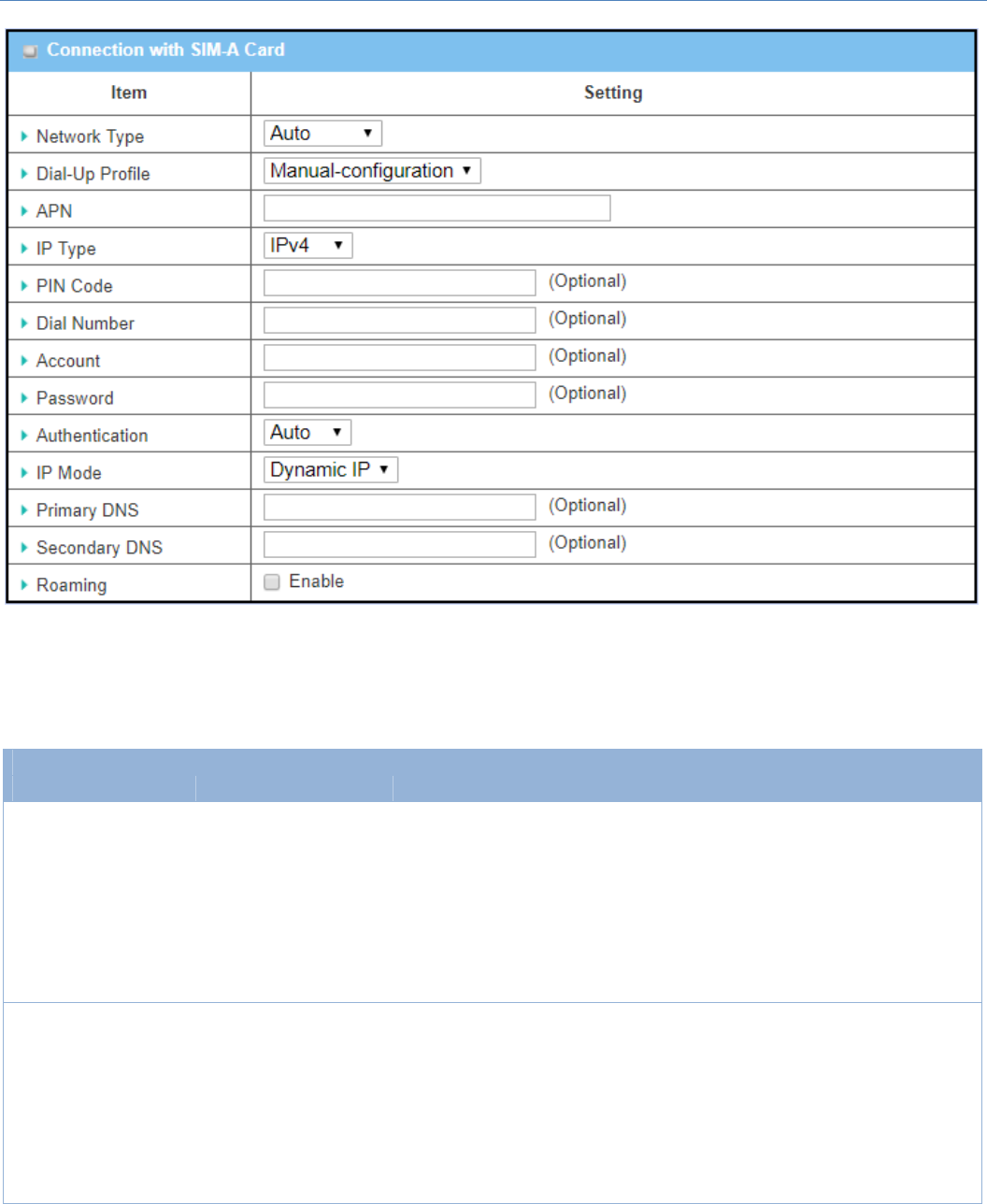
ConfigureSIM‐A/SIM‐BCard
Hereyoucansetconfigurationsforthecellularconnectionaccordingtoyoursituationorrequirement.
M2MCellularGateway
37
Note_1:ConfigurationsofSIM‐BCardfollowsthesameruleofConfigurationsofSIM‐ACard,herewelistSIM‐
Aastheexample.
Note_2:BothConnectionwithSIM‐ACardandConnectionwithSIM‐BCardwillpopuponlywhentheSIM‐A
FirstorSIM‐BFirstisselected,otherwiseitonlypopsoutoneofthem.
ConnectionwithSIM‐A/‐BCard
Item Valuesetting Description
NetworkType
1.AMustfilledsetting
2.BydefaultAutois
selected
SelectAuto toregisteranetworkautomatically,regardlessofthenetwork
type.
Select2GOnlytoregisterthe2Gnetworkonly.
Select2GPrefertoregisterthe2Gnetworkfirstifitisavailable.
Select3Gonlytoregisterthe3Gnetworkonly.
Select3GPrefertoregisterthe3Gnetworkfirstifitisavailable.
SelectLTEonlytoregistertheLTEnetworkonly.
Note:Optionsmaybedifferentduetothespecificationofthemodule.
Dial‐UpProfile
1.AMustfilledsetting
2.BydefaultManual‐
configurationisselected
Specifythetypeofdial‐upprofileforyour3G/4Gnetwork.Itcanbe
Manual‐configuration,APNProfileList,orAuto‐detection.
SelectManual‐configurationtosetAPN(AccessPointName),DialNumber,
Account,andPasswordtowhatyourcarrierprovides.
SelectAPNProfileListtosetmorethanoneprofiletodialupinturn,until
theconnectionisestablished.Itwillpopupanewfiled,pleasegotoBasic
Network>WAN&Uplink>InternetSetup>SIM‐AAPNProfileListfor
details.

M2MCellularGateway
38
SelectAuto‐detection toautomaticallybringoutallconfigurationsneeded
whiledialing‐up,bycomparingtheIMSIoftheSIMcardtotherecordlisted
inthemanufacturer’sdatabase.
Note_1:YouarehighlyrecommendedtoselecttheManualorAPNProfile
Listtospecifythenetworkforyoursubscription.YourISPalwaysprovides
suchnetworksettingsforthesubscribers.
Note_2:IfyouselectAuto‐detection,itislikelytoconnecttoimproper
network,orfailedtofindavalidAPNforyourISP.
APN
1.AMustfilledsetting
2.Stringformat:any
text
EntertheAPN youwanttousetoestablishtheconnection.
Thisisamust‐filledsettingifyouselectedManual‐configurationasdial‐up
profilescheme.
IPType
1.AMustfilledsetting
2.BydefaultIPv4is
selected
SpecifytheIPtypeofthenetworkserveiceprovidedbyyour3G/4G
network.ItcanbeIPv4,IPv6,orIPv4/6.
PINcode
1.AnOptionalsetting
2.Stringformat:
interger
Enter the PIN (Personal Identification Number) code if it needstounlock
yourSIMcard.
DialNumber,
Account,
Password
1.AnOptionalsetting
2.Stringformat:any
text
EntertheoptionalDialNumber,Account,andPasswordsettingsifyourISP
providedsuchsettingstoyou.
Note: These settings are only displayed when Manual‐configuration is
selected.
Authentication
1.AMustfilledsetting
2.BydefaultAutois
selected
SelectPAP (PasswordAuthenticationProtocol)andusesuchprotocoltobe
authenticatedwiththecarrier’sserver.
SelectCHAP(ChallengeHandshakeAuthenticationProtocol)andusesuch
protocoltobeauthenticatedwiththecarrier’sserver.
WhenAutoisselected,itmeansitwillauthenticatewiththeservereither
PAPorCHAP.
IPMode
1.AMustfilledsetting
2.BydefaultDynamicIP
isselected
WhenDynamicIP isselected,itmeansitwillgetallIPconfigurationsfrom
thecarrier’sserverandsettothedevicedirectly.
Ifyouhavespecificapplicationprovidedbythecarrier,andwanttosetIP
configurationsonyourown,youcanswitchtoStaticIPmodeandfillinall
parametersthatrequired,suchasIPaddress,subnetmaskandgateway.
Note:IPSubnetMaskisamustfilledsetting,andmakesureyouhavethe
rightconfiguration.Otherwise,theconnectionmaygetissues.
PrimaryDNS
1.AnOptionalsetting
2.Stringformat:IP
address(IPv4type)
EntertheIPaddresstochangetheprimaryDNS(DomainNameServer)
setting.Ifitisnotfilled‐in,theserveraddressisgivenbythecarrierwhile
dialing‐up.
SecondaryDNS
1.AnOptionalsetting
2.Stringformat:IP
address(IPv4type)
EntertheIPaddresstochangethesecondaryDNS(DomainNameServer)
setting.Ifitisnotfilled‐in,theserveraddressisgivenbythecarrierwhile
dialing‐up.
Roaming Theboxisuncheckedby
default
Checktheboxtoestablishtheconnectioneventheregistrationstatusis
roaming,notinhomenetwork.
Note:Itmaycostadditionalchargesiftheconnectionisunderroaming.
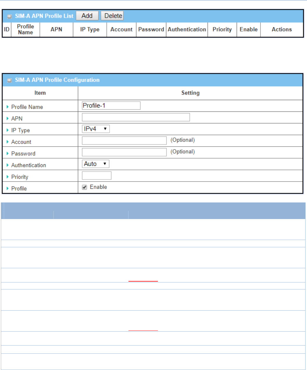
Create/EditSIM‐A/SIM‐BAPNProfileList
YoucanaddanewAPNprofilefortheconnection,ormodifythecontentoftheAPNprofileyouadded.Itis
availableonlywhenyouselectDial‐UpProfileasAPNProfileList.
M2MCellularGateway
39
ListalltheAPNprofileyoucreated,easilyforyoutocheckandmodify.Itisavailableonlywhenyouselect
Dial‐UpProfileasAPNProfileList.
WhenAddbuttonisapplied,anAPNProfileConfigurationscreenwillappear.
SIM‐A/‐BAPNProfileConfiguration
Item Valuesetting Description
ProfileName
1.BydefaultProfile‐xis
listed
2.Stringformat:anytext
Entertheprofilenameyouwanttodescribeforthisprofile.
APN Stringformat:anytext EntertheAPN youwanttousetoestablishtheconnection.
IPType
1.AMustfilledsetting
2.BydefaultIPv4is
selected
SpecifytheIPtypeofthenetworkserveiceprovidedbyyour3G/4G
network.ItcanbeIPv4,IPv6,orIPv4/6.
Account Stringformat:anytext EntertheAccount youwanttousefortheauthentication.
ValueRange:0~53characters.
Password Stringformat:anytext EnterthePassword youwanttousefortheauthentication.
Authentication
1.AMustfilledsetting
2.BydefaultAutois
selected
SelecttheAuthenticationmethodforthe3G/4Gconnection.
ItcanbeAuto,PAP,CHAP,orNone.
Priority 1.AMustfilledsetting
2.Stringformat:integer
Enterthevalueforthedialing‐uporder.Thevalidvalueisfrom1to16.It
willstarttodialupwiththeprofilethatassignedwiththesmallestnumber.
ValueRange:1~16.
Profile Theboxischeckedby
default
Checktheboxtoenablethisprofile.
Unchecktheboxtodisablethisprofileindialing‐upaction.
Save N/A ClicktheSavebuttontosavetheconfiguration.
Undo N/A ClicktheUndobuttontorestorewhatyoujustconfiguredbacktothe
previoussetting.
M2MCellularGateway
40
Back N/A WhentheBackbuttonisclicked,thescreenwillreturntotheprevious
page.
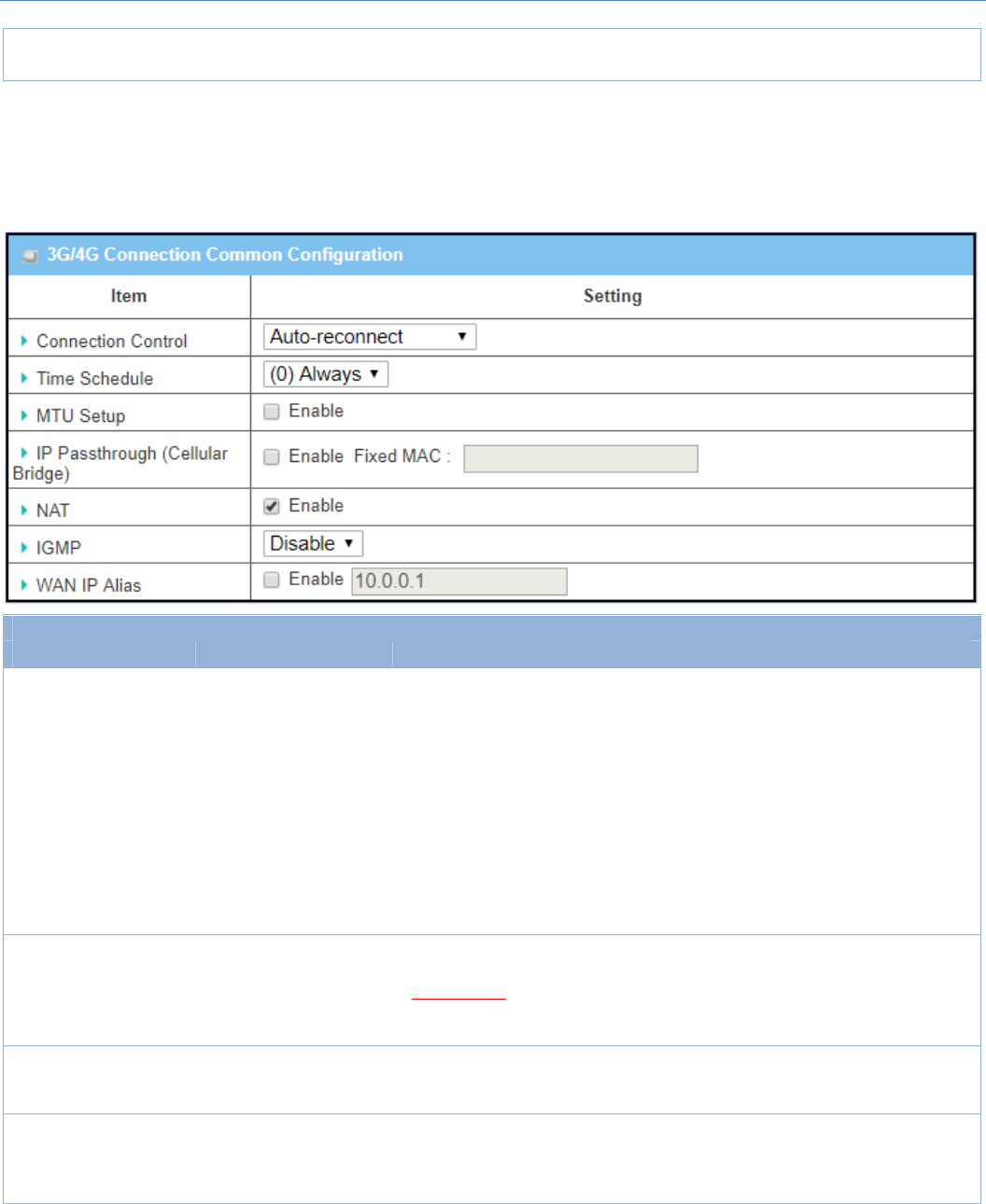
Setup3G/4GConnectionCommonConfiguration
Hereyoucanchangecommonconfigurationsfor3G/4GWAN.
3G/4GConnectionCommonConfiguration
Item Valuesetting Description
ConnectionControl BydefaultAuto‐
reconnectisselected
WhenAuto‐reconnect isselected,itmeansitwilltrytokeepthe Internet
connectiononallthetimewheneverthephysicallinkisconnected.
WhenConnect‐on‐demandisselected,itmeanstheInternetconnection
willbeestablishedonlywhendetectingdatatraffic.
WhenConnectManuallyisselected,itmeansyouneedtoclickthe
Connectbuttontodialuptheconnectionmanually.PleasegotoStatus>
BasicNetwork>WAN&Uplinktabfordetails.
Note:IftheWANinterfaceservesastheprimaryoneforanotherWAN
interfaceinFailoverrole(andviceversa),theConnectionControl
parameterwillnotbeavailableonbothWANsasthesystemmustsetitto
“Auto‐reconnect”
MaximumIdleTime
1.AnOptionalsetting
2.Bydefault600
secondsisfilled‐in
SpecifythemaximumIdletimesettingtodisconnecttheinternet
connectionwhentheconnectionidletimedout.
ValueRange:300~86400.
Note:ThisfieldisavailableonlywhenConnect‐on‐demandorConnect
Manuallyisselectedastheconnectioncontrolscheme.
TimeSchedule
1.AMustfilledsetting
2.Bydefault(0)Always
isselected
When(0)Always isselected,itmeansthisWANisunderoperationallthe
time.Onceyouhavesetotherschedulerules,therewillbeotheroptionsto
select.PleasegotoObjectDefinition>Schedulingfordetails.
MTUSetup 1.AnOptionalsetting
2.Uncheckbydefault
ChecktheEnableboxtoenabletheMTU(MaximumTransmissionUnit)
limit,andspecifytheMTUforthe3G/4Gconnection.
MTUreferstoMaximumTransmissionUnit.Itspecifiesthelargestpacket
sizepermittedforInternettransmission.
M2MCellularGateway
41
ValueRange:1200~1500.
IPPass‐through
(CellularBridge)
1.Theboxisunchecked
bydefault
2.StringformatforFixed
MAC:
MACaddress,e.g.
00:50:18:aa:bb:cc
WhenEnable boxischecked,itmeansthedevicewilldirectlyassignthe
WANIPtothefirstconnectedlocalLANclient.
However,whenanoptionalFixedMACisfilled‐inanon‐zerovalue,it
meansonlytheclientwiththisMACaddresscangettheWANIPaddress.
Note:WhentheIPPass‐throughison,NATandWANIPAliaswillbe
unavailableuntilthefunctionisdisabledagain.
NAT Checkbydefault UnchecktheboxtodisableNAT (NetworkAddressTranslation)function.
IGMP BydefaultDisableis
selected
SelectAuto to enableIGMP function.
ChecktheEnableboxtoenableIGMPProxy.
WANIPAlias
1.Uncheckedbydefault
2.Stringformat:IP
address(IPv4type)
ChecktheboxtoenableWANIPAlias,andfillintheIPaddressyouwantto
assign.
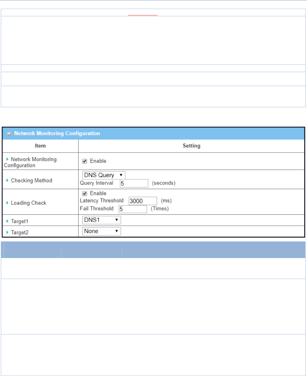
NetworkMonitoringConfiguration
Item Valuesetting Description
NetworkMonitoring
Configuration
1.Anoptionalsetting
2.Boxischeckedby
default
ChecktheEnable boxtoactivatethenetworkmonitoringfunction.
CheckingMethod
1.AnOptionalsetting
2.DNSQueryissetby
default
ChooseeitherDNSQuery orICMPCheckingtodetectWANlink.
WithDNSQuery,thesystemcheckstheconnectionbysendingDNSQuery
packetstothedestinationspecifiedinTarget1andTarget2.
WithICMPChecking,thesystemwillcheckconnectionbysendingICMP
requestpacketstothedestinationspecifiedinTarget1andTarget2.
QueryIntervaldefinesthetransmittingintervalbetweentwoDNSQueryor
ICMPcheckingpackets.
LoadingCheck
1.Anoptionalsetting
2.Boxischeckedby
default
ChecktheEnable boxtoactivatetheloadingcheckfunction.
EnableLoadingCheckallowsthegatewaytoignoreunreturnedDNS
queriesorICMPrequestswhenWANbandwidthisfullyoccupied.Thisisto
preventfalselink‐downstatus.
LatencyThresholddefinesthetolerancethresholdofrespondingtime.

M2MCellularGateway
42
FailThreshold specifies thedetecteddisconnectionbeforetherouter
recognizetheWANlinkdownstatus.Enteranumberofdetecting
disconnectiontimestobethethresholdbeforedisconnectionis
acknowledged.
Target1
1.AnOptionalfilled
setting
2.DNS1isselectedby
default
Target1 specifies thefirsttargetofsendingDNSquery/ICMPrequest.
DNS1:settheprimaryDNStobethetarget.
DNS2:setthesecondaryDNStobethetarget.
Gateway:settheCurrentgatewaytobethetarget.
OtherHost:enteranIPaddresstobethetarget.
Target2
1.AnOptionalfilled
setting
2.Noneisselectedby
default
Target1 specifies thesecond targetofsendingDNSquery/ICMPrequest.
None:nosecondtargetisrequired.
DNS1:settheprimaryDNStobethetarget.
DNS2:setthesecondaryDNStobethetarget.
Gateway:settheCurrentgatewaytobethetarget.
OtherHost:enteranIPaddresstobethetarget.
Save N/A ClickSave tosavethesettings.
Undo N/A ClickUndo tocancelthesettings.
M2MCellularGateway
43
2.2LAN&VLAN
ThissectionprovidestheconfigurationofLANandVLAN.VLANisanoptionalfeature,anditdependsonthe
productspecificationofthepurchasedgateway.
2.2.1EthernetLAN
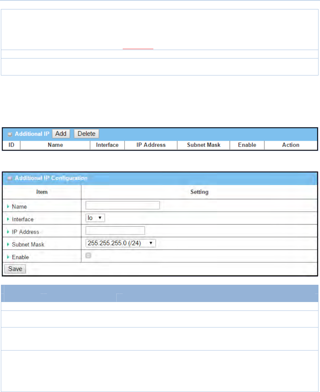
The Local Area Network (LAN) can be
used to share data or files among
computers attached to a network.
Following diagram illustrates the
networkthatwiredandinterconnects
computers.
PleasefollowthefollowinginstructionstodoIPv4EthernetLANSetup.
Configuration
Item Valuesetting Description
IPMode N/A
ItshowstheLANIPmodeforthegatewayaccordingtherelatedconfiguration.
StaticIP:IfthereisatleastoneWANinterfaceactivated,theLANIPmodeis
fixedinStaticIPmode.
DynamicIP:IfalltheavailableWANinferfacesaredisabled,theLANIPmode
canbeDynamicIPmode.
LANIP
Address
1.AMustfilledsetting
2.192.168.123.254issetby
default
EnterthelocalIPaddressofthisdevice.
Thenetworkdevice(s)onyournetworkmustusetheLANIPaddressofthis
deviceastheirDefaultGateway.Youcanchangeitifnecessary.
Note:It’salsotheIPaddressofwebUI.Ifyouchangeit,youneed
totypenewIPaddressinthebrowsertoseewebUI.
SubnetMask 1.AMustfilledsetting
2.255.255.255.0(/24)isset
Selectthesubnetmaskforthisgatewayfromthedropdownlist.
Subnetmaskdefineshowmanyclientsareallowedinonenetworkorsubnet.
M2MCellularGateway
44
bydefault Thedefaultsubnetmaskis255.255.255.0(/24),anditmeansmaximum254IP
addressesareallowedinthissubnet.However,oneofthemisoccupiedbyLAN
IPaddressofthisgateway,sotherearemaximum253clientsallowedinLAN
network.
ValueRange:255.0.0.0(/8)~255.255.255.252(/30).
Save N/A ClicktheSavebuttontosavetheconfiguration
Undo N/A ClicktheUndobuttontorestorewhatyoujustconfiguredbacktotheprevious
setting.
Create/EditAdditionalIP
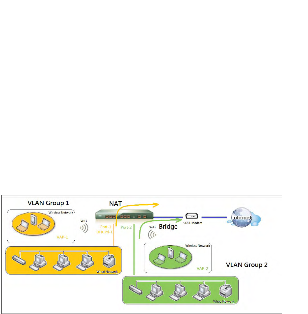
ThisgatewayprovidestheLANIPaliasfunctionforsomespecialmanagementconsideration.Youcanadd
additionalLANIPforthisgateway,andaccesstothisgatewaywiththeadditionalIP.
WhenAddbuttonisapplied,AdditionalIPConfigurationscreenwillappear.
Configuration
Item Valuesetting Description
Name .1AnOptionalSetting EnterthenameforthealiasIPaddress.
Interface 1.AMustfilledsetting
2.loissetbydefault SpecifytheInterfacetype.Itcanbeloorbr0.
IPAddress
1.AnOptionalsetting
2.192.168.123.254issetby
default
EntertheadditionIPaddressforthisdevice.
SubnetMask
1.AMustfilledsetting
2.255.255.255.0(/24)isset
bydefault
Selectthesubnetmaskforthisgatewayfromthedropdownlist.
Subnetmaskdefineshowmanyclientsareallowedinonenetworkorsubnet.
Thedefaultsubnetmaskis255.255.255.0(/24),anditmeansmaximum254IP
addressesareallowedinthissubnet.However,oneofthemisoccupiedbyLAN
IPaddressofthisgateway,sotherearemaximum253clientsallowedinLAN

M2MCellularGateway
45
network.
ValueRange:255.0.0.0(/8)~255.255.255.255(/32).
Save NA ClicktheSavebuttontosavetheconfiguration
M2MCellularGateway
46
2.2.2VLAN
VLAN(VirtualLAN) is alogicalnetworkunder a certain switchorrouterdevicetogroupclienthostswitha
specific VLAN ID. This gateway supports both Port‐based VLAN andTag‐basedVLAN.Thesefunctionsallow
you to divide local network into different “virtual LANs”. It is common requirement for some application
scenario. For example, there arevariousdepartmentswithinSMB. All client hosts in the same department
should own common access privilege and QoS property. You can assigndepartmentseitherbyport‐based
VLANortag‐basedVLANasagroup,andthenconfigureitbyyourplan.Insomecases,ISPmayneedrouterto
support“VLANtag”forcertainkindsofservices(e.g.IPTV).Youcangroupalldevicesrequiredthisserviceas
onetag‐basedVLAN.
IfthegatewayhasonlyonephysicalEthernetLANport,onlyvery limited configuration is available if you
enablethePort‐basedVLAN.
Port‐basedVLAN
Port‐basedVLANfunctioncangroupEthernetports,Port‐1~Port‐4,andWiFiVirtualAccessPoints,VAP‐1~
VAP‐8,togetherfordifferentiatedserviceslikeInternetsurfing,multimediaenjoyment,VoIPtalking,andsoon.
Twooperationmodes,NATandBridge,canbeappliedtoeachVLANgroup.OneDHCPservercanbeallocated
foraNATVLANgrouptoletgrouphostmembergetitsIPaddress.Thus,eachhostcansurfInternetviathe
NATmechanismofbusinessaccessgateway.Inbridgemode,IntranetpacketflowisdeliveredoutWANtrunk
portwithVLANtagtoupperlinkfordifferentservices.
Aport‐basedVLANisagroupofportsonanEthernetorVirtualAPsofWiredorWirelessGatewaythatforma
logicalLANsegment.Followingisanexample.
Forexample,inacompany,administratorschemesout3networksegments, Lobby/Meeting Room, Office,
and Data Center. In a Wireless Gateway, administrator can configure Lobby/Meeting Room segment with
VLAN ID 3. The VLAN group includes Port‐3 and VAP‐8 (SSID: Guest) with NAT mode and DHCP‐3 server
equipped.HealsoconfigureOfficesegmentwithVLANID2.TheVLANgroupincludesPort‐2andVAP‐1(SSID:
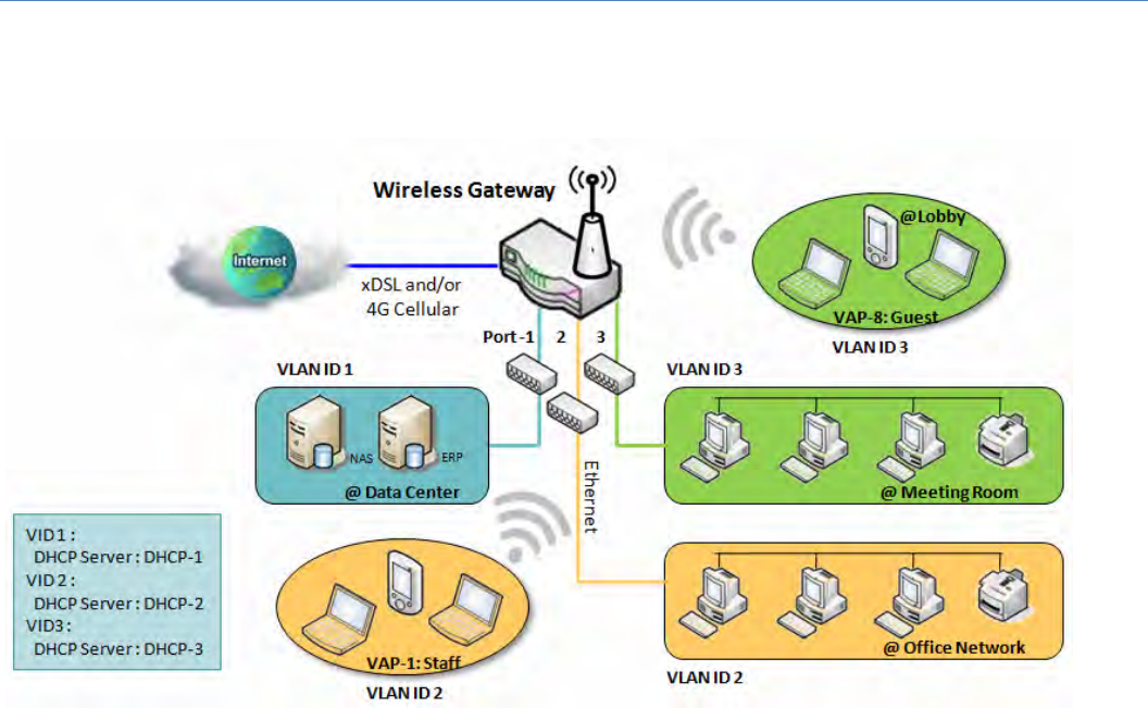
M2MCellularGateway
47
Staff)withNATmodeandDHCP‐2serverequipped.Atlast,administratoralsoconfigureDataCentersegment
with VLAN ID 1. The VLAN group includes Port‐1 with NAT mode to WAN interface as shown in following
diagram.
Aboveisthegeneralcasefor3EthernetLANportsinthegateway.ButifthedevicejusthasoneEthernetLAN
port,therewillbeonlyoneVLANgroupforthedevice.Undersuchsituation,itstillsupportsboththeNATand
BridgemodeforthePort‐basedVLANconfiguration.
Tag‐basedVLAN
Tag‐basedVLANfunctioncangroupEthernetports,Port‐1~Port‐4,andWiFiVirtualAccessPoints,VAP‐1~
VAP‐8,togetherwithdifferentVLANtagsfordeployingsubnetsin Intranet. All packet flows can carry with
different VLAN tags even at the same physical Ethernet port forIntranet.Theseflowscanbedirectedto
differentdestinationbecausetheyhavedifferentiatedtags.Theapproachisveryusefultogroupsomehosts
atdifferentgeographiclocationtobeinthesameworkgroup.
Tag‐basedVLANisalsocalledaVLANTrunk.TheVLANTrunkcollectsallpacketflowswithdifferentVLANIDs
fromRouterdeviceanddeliversthemintheIntranet.VLANmembershipinataggedVLANisdeterminedby
VLAN ID information within the packetframes that are received onaport.Administratorcanfurtherusea
VLANswitchtoseparatetheVLANtrunktodifferentgroupsbasedonVLANID.Followingisanexample.
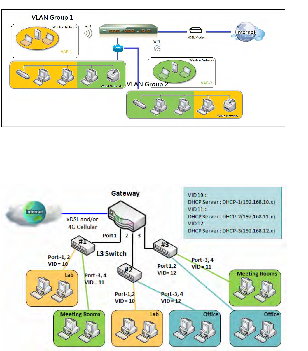
M2MCellularGateway
48
Forexample,inacompany,administratorschemesout3networksegments,Lab,MeetingRooms,andOffice.
InaSecurityVPNGateway,administratorcanconfigureOfficesegmentwithVLANID12.TheVLANgroupis
equippedwithDHCP‐3servertoconstructa192.168.12.xsubnet.HealsoconfigureMeetingRoomssegment
with VLAN ID 11. The VLAN group is equipped with DHCP‐2 server to construct a 192.168.11.x subnet for
Intranet only. That is,any client host in VLAN 11group can’t accessthe Internet.Atlast, he configuresLab
segmentwithVLANID10.TheVLANgroupisequippedwithDHCP‐1servertoconstructa192.168.10.xsubnet.
M2MCellularGateway
49
VLANGroupsAccessControl
Administrator can specify the Internet access permission for all VLAN groups. He can also configure which
VLANgroupsareallowedtocommunicatewitheachother.
VLANGroupInternetAccess
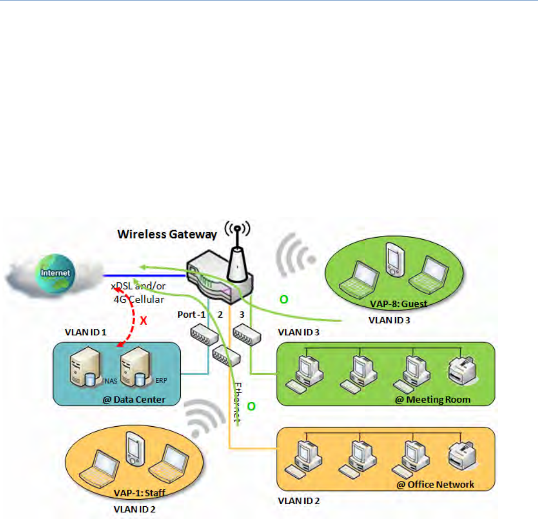
AdministratorcanspecifymembersofoneVLANgrouptobeable toaccessInternet ornot.Followingisan
examplethatVLANgroupsofVIDis2and3canaccessInternetbut the one with VID is 1 cannot access
Internet. That is, visitors in meeting room and staffs in office network can access Internet. But the
computers/serversindatacentercannotaccessInternetsincesecurityconsideration.Serversindatacenter
onlyfortrustedstaffsorareaccessedinsecuretunnels.
M2MCellularGateway
50
InterVLANGroupRouting:
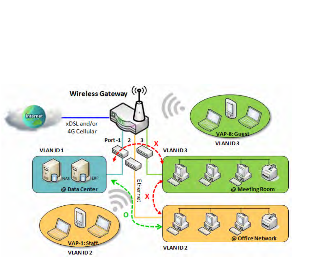
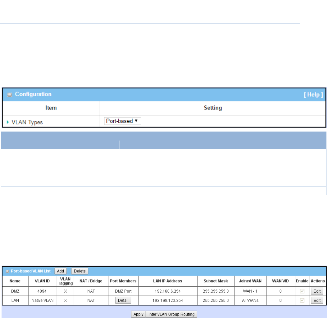
InPort‐basedtagging,administratorcanspecifymemberhostsofoneVLANgrouptobeabletocommunicate
withtheonesofanotherVLANgroupornot.Thisisacommunicationpair,andoneVLANgroupcanjoinmany
communication pairs. But communication pair doesn’t have the transitive property. That is, A can
communicate with B, and B can communicate with C, it doesn’t implythatAcancommunicatewithC.An
example is shown atfollowing diagram. VLAN groups of VID is 1and 2 can access each other but the ones
betweenVID1andVID3andbetweenVID2andVID3can’t.
M2MCellularGateway
51
VLANSetting
GotoBasicNetwork>LAN&VLAN>VLANTab.
TheVLANfunctionallowsyoutodividelocalnetworkintodifferentvirtualLANs.TherearePort‐basedand
Tag‐basedVLANtypes.Selectonethatapplies.
Configuration
Item Valuesetting Description
VLANType Port‐basedisselectedby
default
Select theVLANtypethatyouwanttoadopt fororganizingyoulocalsubnets.
Port‐based:Port‐basedVLANallowsyoutoaddruleforeachLANport,andyou
candoadvancedcontrolwithitsVLANID.
Tag‐based:Tag‐basedVLANallowsyoutoaddVLANID,andselectmemberand
DHCPServerforthisVLANID.GotoTag‐basedVLANListtable.
Save NA ClicktheSavebuttontosavetheconfiguration
Port‐basedVLAN–Create/EditVLANRules
Theport‐basedVLANallowsyoutocustomeachLANport.Thereisadefaultruleshowstheconfigurationofall
LANports.Also,ifyourdevicehasaDMZport,youwillseeDMZconfiguration,too.Themaximarulenumbers
isbasedonLANportnumbers.
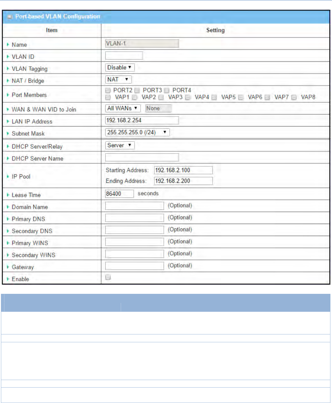
WhenAddbuttonisapplied,Port‐basedVLANConfigurationscreenwillappear,whichisincluding3sections:
Port‐basedVLANConfiguration,IPFixedMappingRuleList,andInterVLANGroupRouting(enterthrougha
button)
Port‐basedVLAN‐Configuration
M2MCellularGateway
52
Port‐basedVLANConfiguration
Item Valuesetting Description
Name
1.AMustfilledsetting
2.Stringformat:already
havedefaulttexts
DefinetheName ofthisrule.Ithasadefaulttextandcannotbemodified.
VLANID AMustfilledsetting Definethe VLANIDnumber,rangeis1~4094.
VLANTagging Disableisselectedby
default.
TheruleisactivatedaccordingtoVLANID andPortMembersconfiguration
whenEnableisselected.
TheruleisactivatedaccordingPortMembersconfigurationwhenDisableis
selected.
NAT/Bridge NATisselectedbydefault. SelectNAT modeorBridge modefortherule.
PortMembers Theseboxisuncheckedby
default.
SelectwhichLANport(s) andVAP(s) thatyouwanttoaddtotherule.
Note:Theavailablememberlistcanbedifferentforthepurchasedproduct.

M2MCellularGateway
53
WAN&WAN
VIDtoJoin
AllWANsisselectedby
default.
SelectwhichWAN orAllWANs thatallowaccessingInternet.
Note:IfBridgemodeisselected,youneedtoselectaWANandenteraVID.
LANIP
Address AMustfilledsetting Assignan IPAddressfortheDHCPServerthattheruleused,thisIPaddressisa
gatewayIP.
SubnetMask 255.255.255.0(/24)is
selectedbydefault.
Selecta SubnetMask fortheDHCPServer.
DHCPServer
/Relay Serverisselectedbydefault.
DefinetheDHCPServertype.
Therearethreetypesyoucanselect:Server,Relay,andDisable.
Relay:SelectRelaytoenableDHCPRelayfunctionfortheVLANgroup,andyou
onlyneedtofilltheDHCPServerIPAddressfield.
Server:SelectServertoenableDHCPServerfunctionfortheVLANgroup,and
youneedtospecifytheDHCPServersettings.
Disable:SelectDisabletodisabletheDHCPServerfunctionfortheVLANgroup.
DHCPServer
IPAddress
(forDHCP
Relayonly)
AMustfilledsetting
IfyouselectRelay typeofDHCPServer,assignaDHCPServerIPAddress that
thegatewaywillrelaytheDHCPrequeststotheassignedDHCPserver.
DHCPServer
Name AMustfilledsetting DefinenameoftheDHCPServer forthespeci
f
iedVLANgroup.
IPPool AMustfilledsetting
DefinetheIPPoolrange.
ThereareStartingAddressandEndingAddressfields.IfaclientrequestsanIP
addressfromthisDHCPServer,itwillassignanIPaddressintherangeofIP
pool.
LeaseTime AMustfilledsetting DefineaperiodoftimeforanIPAddressthattheDHCPServerleasestoanew
device.Bydefault,theleasetimeis86400seconds.
DomainName Stringformatcanbeany
text
TheDomainNameofthisDHCPServer.
ValueRange:0~31characters.
PrimaryDNS IPv4format ThePrimaryDNSofthisDHCPServer.
Secondary
DNS IPv4format TheSecondaryDNSofthisDHCPServer.
PrimaryWINS IPv4format ThePrimaryWINSofthisDHCPServer.
Secondary
WINS IPv4format TheSecondaryWINSofthisDHCPServer.
Gateway IPv4format TheGatewayofthisDHCPServer.
Enable Theboxisuncheckedby
default.
ClickEnableboxtoactivatethisrule.
Save NA ClicktheSavebuttontosavetheconfiguration
Undo NA ClicktheUndobuttontorestorewhatyoujustconfiguredbacktotheprevious
setting.
M2MCellularGateway
54
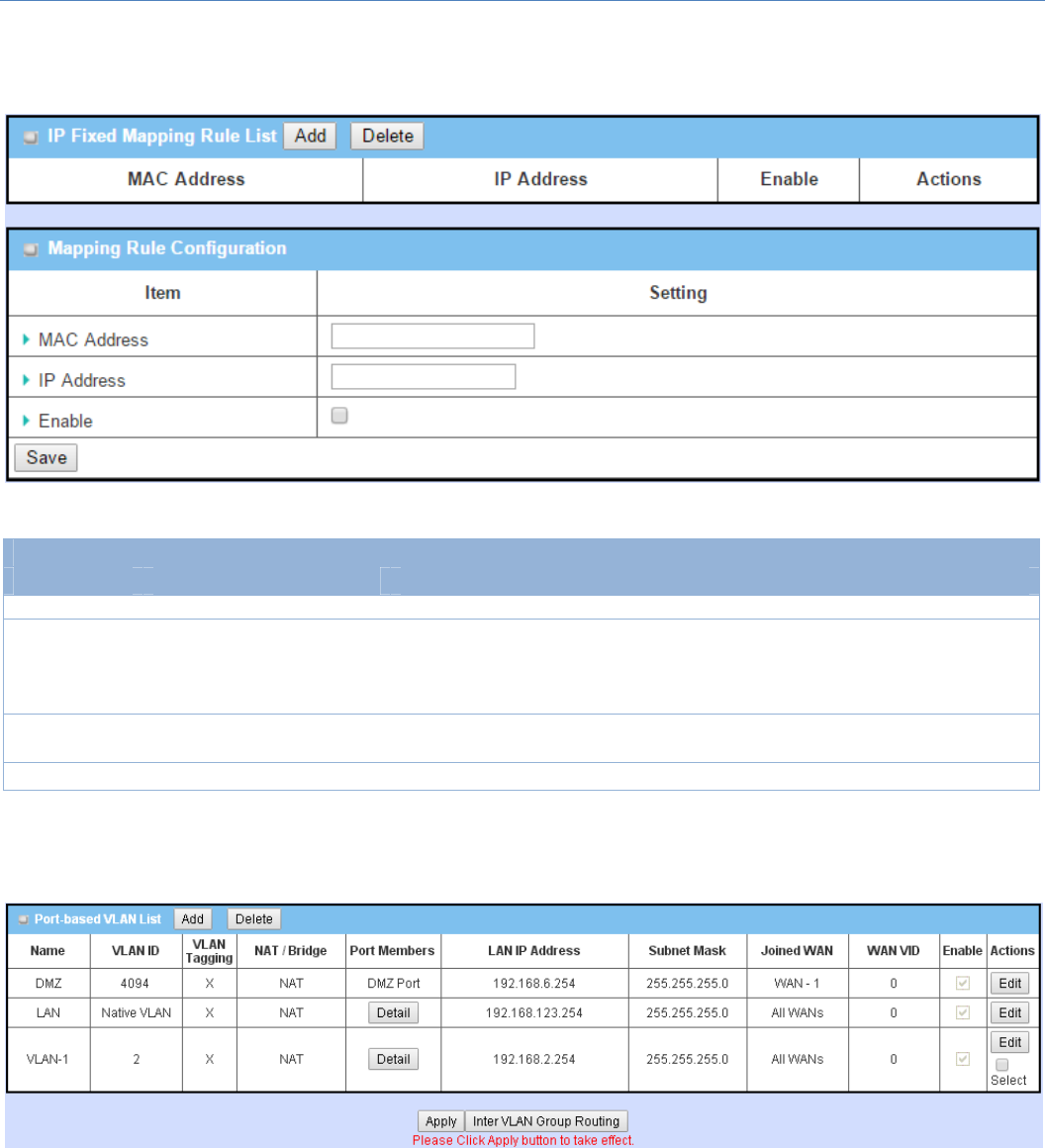
Besides,youcanaddsomeIPrulesintheIPFixedMappingRule ListifDHCPServerfortheVLANgroupsis
required.
WhenAddbuttonisapplied,MappingRuleConfigurationscreenwillappear.
MappingRuleConfiguration
Item Valuesetting Description
MACAddress AMustfilledsetting DefinetheMACAddresstargetthattheDHCPServerwantstomatch.
IPAddress AMustfilledsetting
DefinetheIPAddressthattheDHCPServerwillassign.
IfthereisarequestfromtheMACAddressfilledintheabovefield,theDHCP
ServerwillassignthisIPAddresstotheclientwhoseMACAddressmatchedthe
rule.
Enable Theboxisuncheckedby
default.
ClickEnableboxtoactivatethisrule.
Save NA ClicktheSavebuttontosavetheconfiguration
Note:ensuretoalwaysclickonApplybuttontoapplythechangesafterthewebbrowserrefreshedtakenyou
backtotheVLANpage.
M2MCellularGateway
55
Port‐basedVLAN–InterVLANGroupRouting
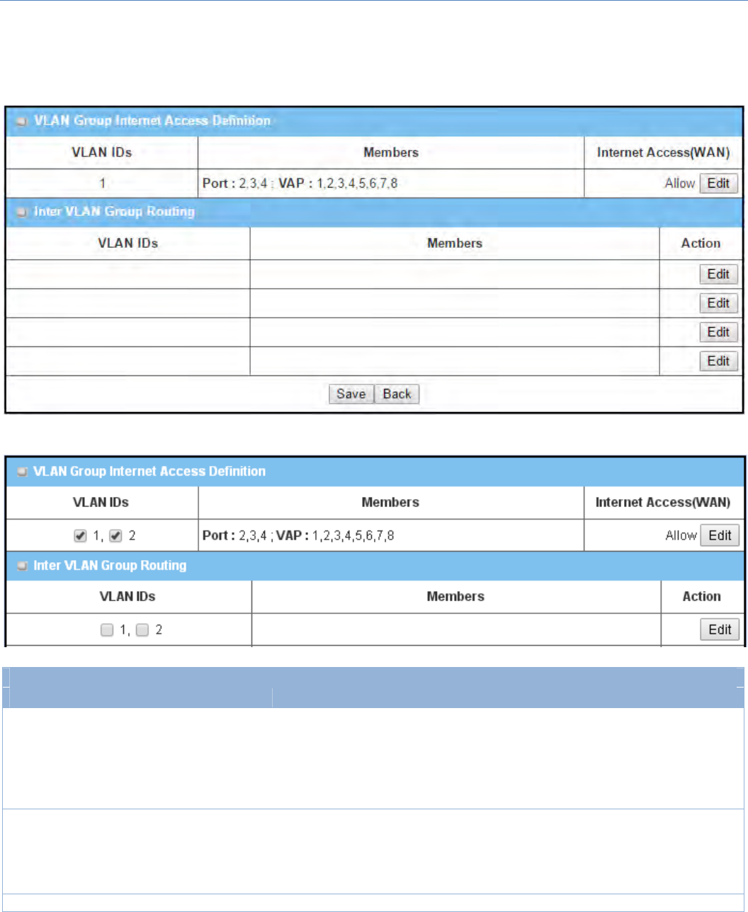
ClickVLANGroupRoutingbutton,theVLANGroupInternetAccessDefinitionandInterVLANGroupRouting
screenwillappear.
WhenEditbuttonisapplied,ascreensimilartothiswillappear.
InterVLANGroupRouting
Item Valuesetting Description
VALNGroup
Internet
Access
Definition
Allboxesarecheckedby
default.
Bydefault,allboxesarecheckedmeansallVLANIDmembersareallowto
accessWANinterface.
IfuncheckacertainVLANIDbox,itmeanstheVLANIDmembercan’taccess
Internetanymore.
Note:VLANID1isavailablealways;itisthedefaultVLANIDofLANrule.The
otherVLANIDsareavailableonlywhentheyareenabled.
InterVLAN
GroupRouting
Theboxisuncheckedby
default.
ClicktheexpectedVLANIDsboxtoenabletheInterVLANaccessfunction.
Bydefault,membersindifferentVLANIDscan’taccesseachother.Thegateway
supportsupto4rulesforInterVLANGroupRouting.
Forexample,ifID_1andID_2arechecked,itmeansmembersinVLANID_1can
accessmembersofVLANID_2,andviceversa.
Save N/A ClicktheSavebuttontosavetheconfiguration
M2MCellularGateway
56
Tag‐basedVLAN–Create/EditVLANRules
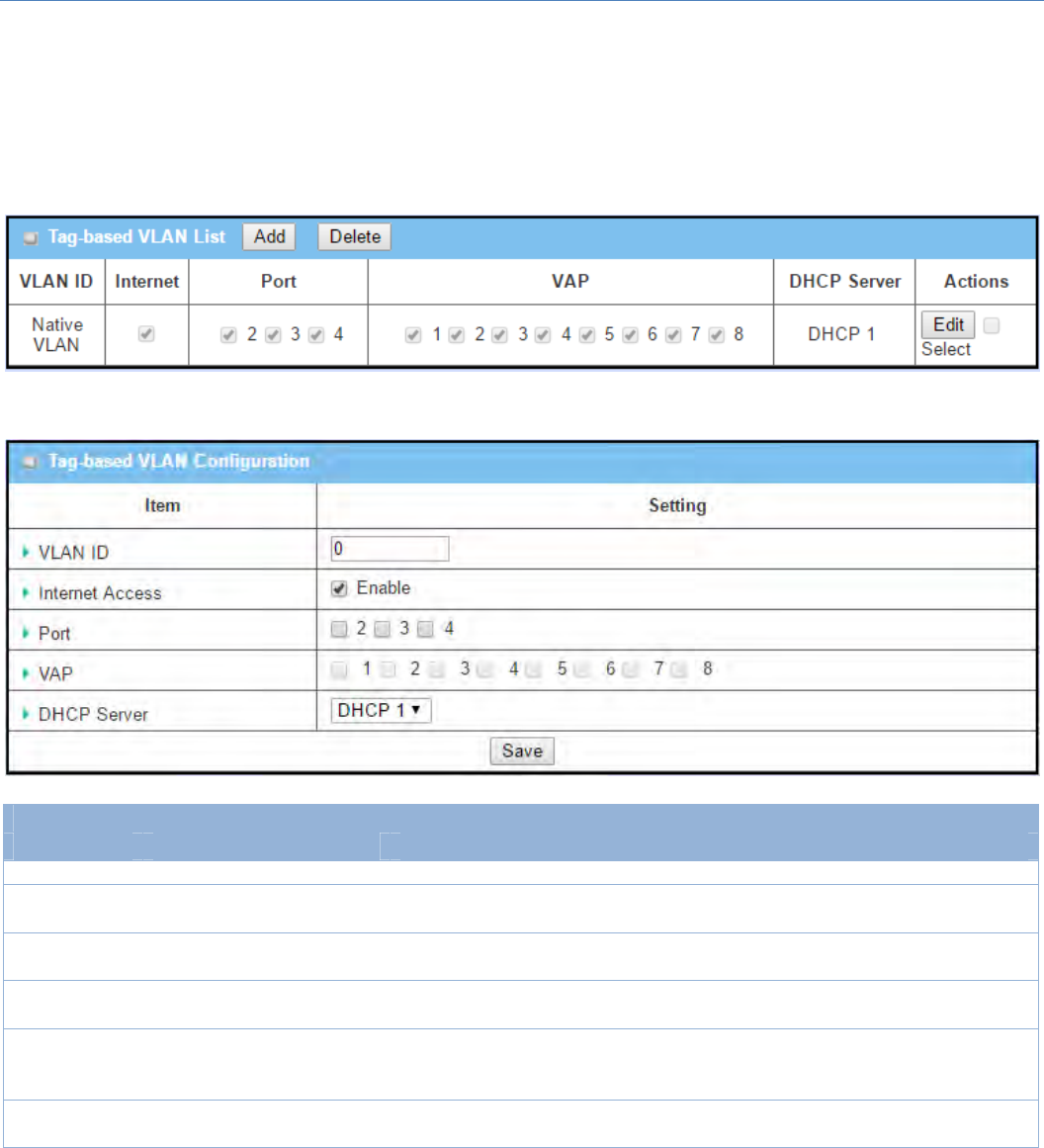
The Tag‐based VLAN allowsyoutocustomizeeachLANportaccordingtoVLANID.There is a default rule
showstheconfigurationofallLANportsandallVAPs.Also,ifyourdevicehasaDMZport,youwillseeDMZ
configuration,too.Theroutersupportsuptoamaximumof128tag‐basedVLANrulesets.
WhenAddbuttonisapplied,Tag‐basedVLANConfigurationscreenwillappear.
Tag‐basedVLANConfiguration
Item Valuesetting Description
VALNID AMustfilledsetting Definethe VLANID number,rangeis6~4094.
Internet
Access
Theboxischeckedby
default.
ClickEnable boxtoallowthemembersintheVLANgroupaccesstointernet.
Port Theboxisuncheckedby
default.
ChecktheLANportbox(es)tojointheVLANgroup.
VAP Theboxisuncheckedby
default.
ChecktheVAP box(es)tojointheVLANgroup.
Note:OnlythewirelessgatewayhastheVAPlist.
DHCPServer DHCP1isselectedby
default.
Select aDHCPServer tothesemembersofthisVLANgroup.
TocreateoreditDHCPserverforVLAN,refertoBasicNetwork>LAN&VLAN>
DHCPServer.
Save N/A ClickSavebuttontosavetheconfiguration
Note:AfterclickingSavebutton,alwaysclickApplybuttontoapplythesettings.
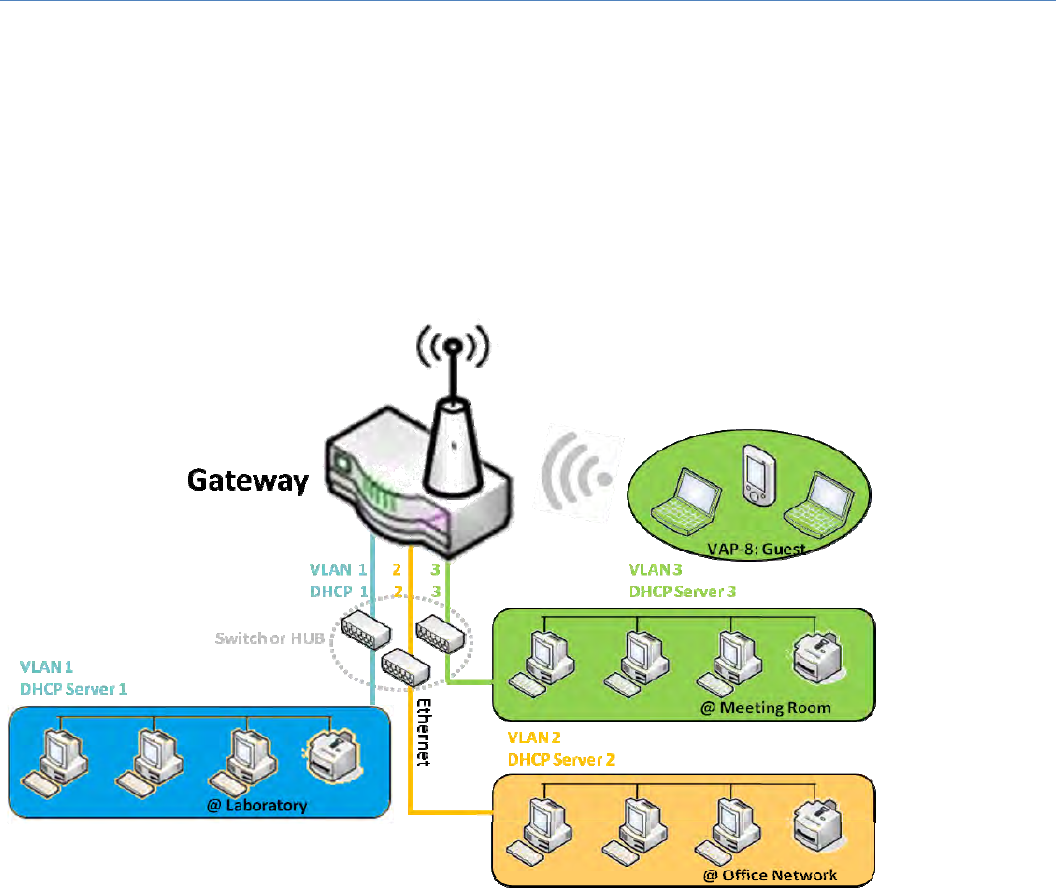
M2MCellularGateway
57
2.2.3DHCPServer
DHCPServer
Thegatewaysupportsupto4DHCPserverstofulfilltheDHCPrequestsfromdifferentVLANgroups(please
refertoVLANsectionforgettingmoreusagedetails).AndthereisonedefaultsettingforwhoseLANIP
AddressisthesameoneofgatewayLANinterface,withitsdefaultSubnetMasksettingas“255.255.255.0”,
anditsdefaultIPPool rangesisfrom “.100”to“.200”asshown at the DHCP Server List page ongateway’s
WEBUI.
UsercanaddmoreDHCPserverconfigurationsbyclickingonthe“Add”buttonbehind“DHCPServerList”,or
clickingonthe“Edit”buttonattheendofeachDHCPServeronlisttoedititscurrentsettings.Besides,user
canselectaDHCPServeranddeleteitbyclickingonthe“Select”check‐boxandthe“Delete”button.
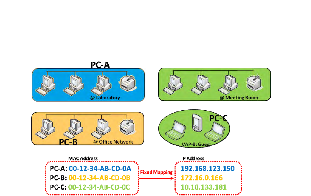
M2MCellularGateway
58
FixedMapping
UsercanassignfixedIPaddresstomapthespecificclientMACaddressbyselectthemthencopy,whentargets
werealreadyexistedintheDHCP Client List, orto add some other Mapping Rules bymanually in advance,
oncethetarget'sMACaddresswasnotreadytoconnect.
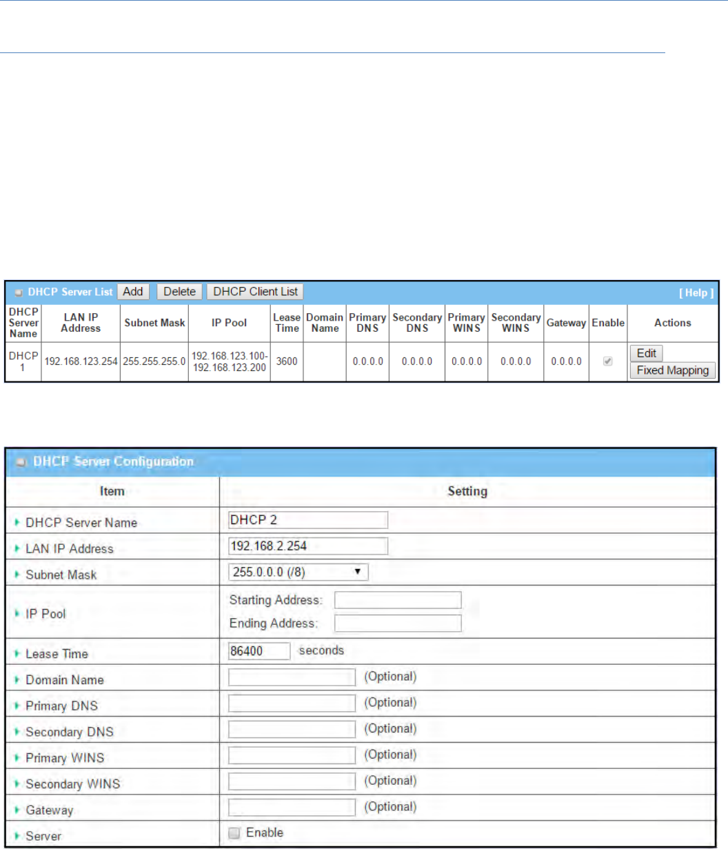
M2MCellularGateway
59
DHCPServerSetting
GotoBasicNetwork>LAN&VLAN>DHCPServerTab.
TheDHCPServersettingallowsusertocreateandcustomizeDHCPServerpoliciestoassignIPAddressesto
thedevicesonthelocalareanetwork(LAN).
Create/EditDHCPServerPolicy
ThegatewayallowsyoutocustomyourDHCPServerPolicy.IfmultipleLANportsareavailable,youcandefine
onepolicyforeachLAN(orVLANgroup),anditsupportsuptoamaximumof4policysets.
WhenAddbuttonisapplied,DHCPServerConfigurationscreenwillappear.
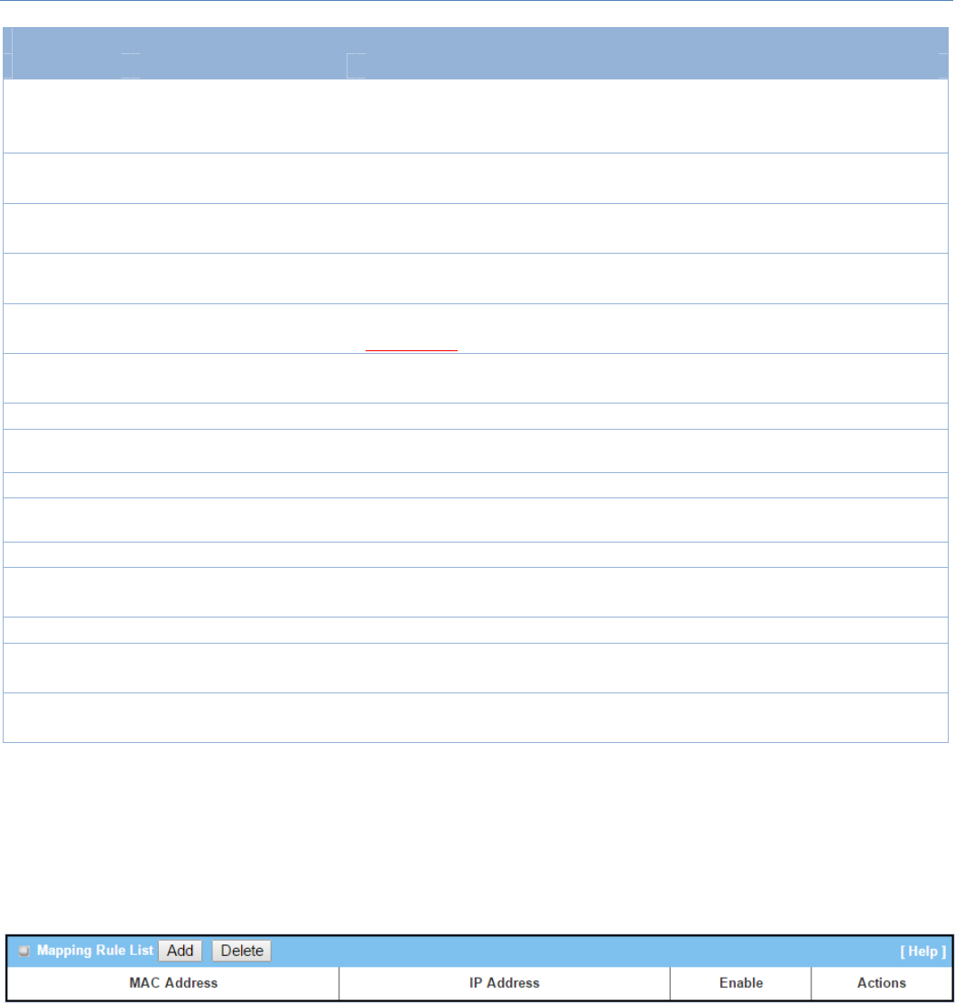
M2MCellularGateway
60
DHCPServerConfiguration
Item Valuesetting Description
DHCPServer
Name
1.Stringformatcanbeany
text
2.AMustfilledsetting
EnteraDHCPServername.Enteranamethatiseasyforyoutounderstand.
LANIP
Address
1.IPv4format.
2.AMustfilledsetting TheLANIPAddressofthisDHCPServer.
SubnetMask 255.0.0.0(/8)issetby
default TheSubnetMaskofthisDHCPServer.
IPPool 1.IPv4format.
2.AMustfilledsetting
TheIPPoolofthisDHCPServer.ItcomposedofStartingAddressenteredinthis
fieldandEndingAddressenteredinthisfield.
LeaseTime 1.Numbericstringformat.
2.AMustfilledsetting
TheLeaseTimeofthisDHCPServer.
ValueRange:300~604800seconds.
DomainName Stringformatcanbeany
text TheDomainNameofthisDHCPServer.
PrimaryDNS IPv4format ThePrimaryDNSofthisDHCPServer.
Secondary
DNS IPv4format TheSecondaryDNSofthisDHCPServer.
PrimaryWINS IPv4format ThePrimaryWINSofthisDHCPServer.
Secondary
WINS IPv4format TheSecondaryWINSofthisDHCPServer.
Gateway IPv4format TheGatewayofthisDHCPServer.
Server Theboxisuncheckedby
default. ClickEnableboxtoactivatethisDHCPServer.
Save N/A ClicktheSavebuttontosavetheconfiguration
Undo N/A ClicktheUndobuttontorestorewhatyoujustconfiguredbacktotheprevious
setting.
Back N/A WhentheBackbuttonisclickedthescreenwillreturntotheDHCPServer
Configurationpage.
Create/EditMappingRuleListonDHCPServer
ThegatewayallowsyoutocustomyourMappingRuleListonDHCPServer.Itsupportsuptoamaximumof64
rulesets.WhenFixMappingbuttonisapplied,theMappingRuleListscreenwillappear.
WhenAddbuttonisapplied,MappingRuleConfigurationscreenwillappear.
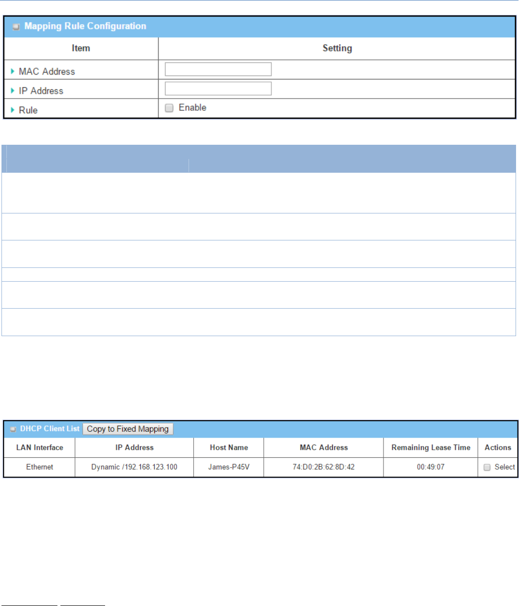
M2MCellularGateway
61
MappingRuleConfiguration
Item Valuesetting Description
MACAddress
1.MACAddressstring
format
2.AMustfilledsetting
TheMACAddressofthismappingrule.
IPAddress 1.IPv4format.
2.AMustfilledsetting TheIPAddressofthismappingrule.
Rule Theboxisuncheckedby
default. ClickEnableboxtoactivatethisrule.
Save N/A ClicktheSavebuttontosavetheconfiguration
Undo N/A ClicktheUndobuttontorestorewhatyoujustconfiguredbacktotheprevious
setting.
Back N/A WhentheBackbuttonisclickedthescreenwillreturntotheDHCPServer
Configurationpage.
View/CopyDHCPClientList
WhenDHCPClientListbuttonisapplied,DHCPClientListscreenwillappear.
WhentheDHCPClientisselectedandCopytoFixedMappingbuttonisapplied.TheIPandMACaddressof
DHCPClientwillapplytotheMappingRuleListonspecificDHCPServerautomatically.
Enable/DisableDHCPServerOptions
TheDHCPServerOptionssettingallowsusertosetDHCPOPTIONS66,72,or114.ClicktheEnablebuttonto
activate the DHCP option function, and the DHCP Server will add the expected options in its sending out
DHCPOFFERDHCPACKpackages.
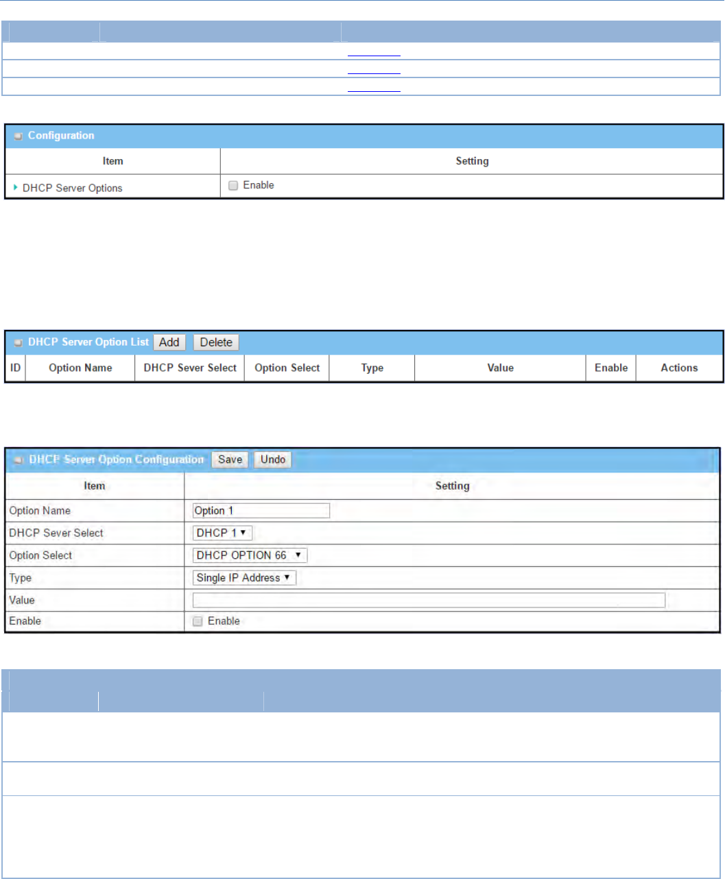
M2MCellularGateway
62
Option Meaning RFC
66 TFTPservername [RFC2132]
72 DefaultWorldWideWebServer [RFC2132]
114 URL [RFC3679]
Create/EditDHCPServerOptions
Thegatewaysupportsuptoamaximumof99optionsettings.
WhenAdd/Editbuttonisapplied,DHCPServerOptionConfigurationscreenwillappear.
DHCPServerOptionConfiguration
Item Valuesetting Description
OptionName
1. String format can be any
text
2.AMustfilledsetting.
EnteraDHCPServerOptionname.Enteranamethatiseasyforyou to
understand.
DHCPServer
Select
Dropdownlistofallavailable
DHCPservers. ChoosetheDHCPserverthisoptionshouldapplyto.
OptionSelect
1.AMustfilledsetting.
2. Option 66 is selected by
default.
Choosethespecificoption fromthedropdownlist.ItcanbeOption66,Option
72,Option144,Option42,Option150,orOption160.
Option42forntpserver;
Option66fortftp;
Option72forwww;
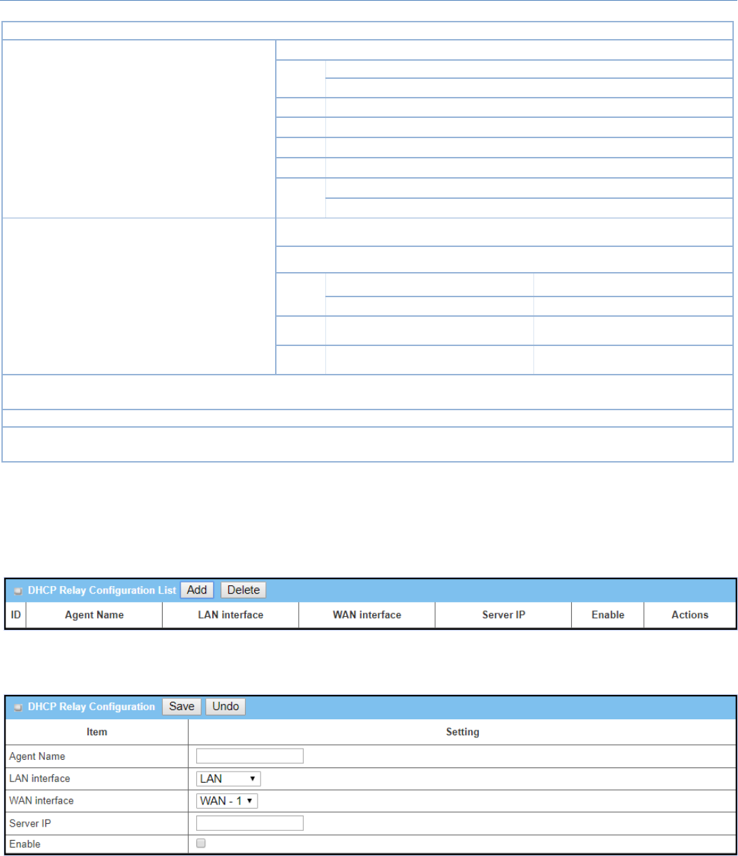
M2MCellularGateway
63
Option144 forurl;
Type DropdownlistofDHCP
serveroptionvalue’stype
Eachdifferentoptionshasdifferentvaluetypes.
66 SingleIPAddress
SingleFQDN
72 IPAddressesList,separatedby“,”
114 SingleURL
42 IPAddressesList,separatedby“,”
150 IPAddressesList,separatedby“,”
160 SingleIPAddress
SingleFQDN
Value
1.IPv4format
2.FQDNformat
3.IPlist
4.URLformat
5.AMustfilledsetting
ShouldconformtoType:
Type Value
66 SingleIPAddress IPv4format
SingleFQDN FQDNformat
72 IPAddressesList,separatedby“,” IPv4format,separatedby“,”
114 SingleURL URLformat
Enable The box is unchecked by
default. ClickEnableboxtoactivatethissetting.
Save NA ClicktheSavebuttontosavethesetting.
Undo NA When the Undo button is clicked the screen will return back with nothing
changed.
Create/EditDHCPRelay
Thegatewaysupportsuptoamaximumof6DHCPRelayconfigurations.
WhenAdd/Editbuttonisapplied,DHCPRelayConfigurationscreenwillappear.

M2MCellularGateway
64
DHCPRelayConfiguration
Item Valuesetting Description
AgentName
1. String format can be any
text
2.AMustfilledsetting.
EnteraDHCPRelayname.Enteranamethatiseasyforyoutounderstand.
ValueRange:1~64characters.
LANInterface 1.AMustfilledsetting.
2.LANisselectedbydefault.
Choose a LAN Interface for the dropdown list to apply with the DHCP Relay
function.
WANInterface
1.AMustfilledsetting.
2. WAN‐1 is selected by
default.
Choose a WAN Interface for the dropdown list to apply with the DHCP Relay
function.ItcanbetheavailableWANinterface(s),andL2TPconnection.
ServerIP 1.AMustfilledsetting.
2.nullbydefault.
AssignaDHCPServerIPAddress thatthegatewaywillrelaytheDHCPrequests
totheassignedDHCPserverviaspecifiedWANinterface.
Enable The box is unchecked by
default. ClickEnableboxtoactivatethissetting.
Save NA ClicktheSavebuttontosavethesetting.
Undo NA When the Undo button is clicked the screen will return back with nothing
changed.

M2MCellularGateway
65
2.3WiFi(notsupported)
Not supported feature for the purchased product, leave it as blank.
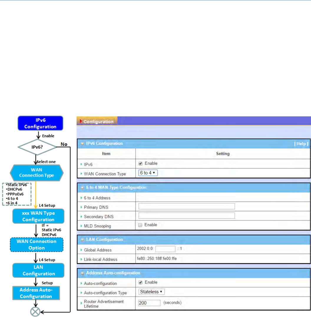
M2MCellularGateway
66
2.4IPv6
ThegrowthoftheInternethascreatedaneedformoreaddressesthanarepossiblewithIPv4.IPv6(Internet
Protocolversion6) is a versionoftheInternetProtocol(IP) intendedtosucceedIPv4, which istheprotocol
currentlyusedtodirectalmostallInternettraffic.IPv6alsoimplementsadditionalfeaturesnotpresentinIPv4.
It simplifies aspects of address assignment (stateless address auto‐configuration),networkrenumberingand
routerannouncementswhenchangingInternetconnectivityproviders.
2.4.1IPv6Configuration
TheIPv6ConfigurationsettingallowsusertosettheIPv6connectiontypetoaccesstheIPv6network.This
gatewaysupportsvarioustypesofIPv6connection,includingStaticIPv6,DHCPv6,andPPPoEv6
Note:Fortheproductsjusthaving3G/4GWANinterface,onlyIPv6issupported.PleasecontactyourISPfor
theIPv6supportsbeforeyouproceedwithIPv6setup.
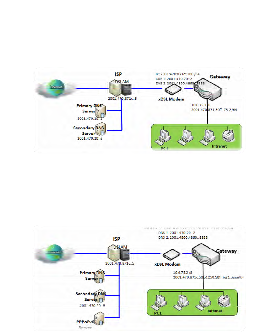
M2MCellularGateway
67
IPv6WANConnectionType
StaticIPv6
StaticIPv6doesthesamefunctionasstaticIPv4.ThestaticIPv6providesmanualsettingofIPv6address,IPv6
defaultgatewayaddress,andIPv6DNS.
AbovediagramdepictstheIPv6IPaddressing,typeintheinformationprovidedbyyourISPtosetuptheIPv6
network.
DHCPv6
DHCPinIPv6doesthesamefunctionasDHCPinIPv4.TheDHCPserversendsIPaddress,DNSserveraddresses
andotherpossibledatatotheDHCPclienttoconfigureautomatically.Theserveralsosendsaleasetimeof
theaddressandtimetore‐contacttheserverforIPv6addressrenewal. The client has then to resend a
requesttorenewtheIPv6address.
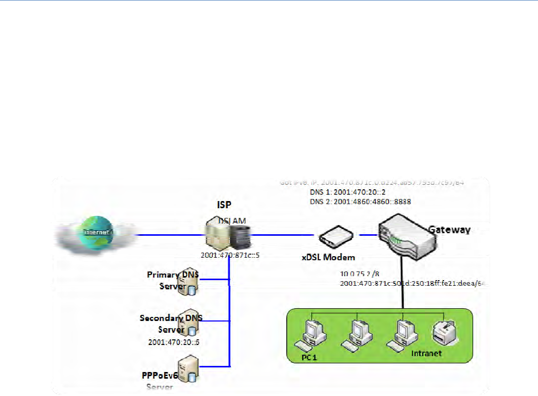
M2MCellularGateway
68
AbovediagramdepictsDHCPIPv6IPaddressing,theDHCPv6serverontheISPsideassignsIPv6address,IPv6
defaultgatewayaddress,andIPv6DNStoclienthost’sautomatically.
PPPoEv6
PPPoEv6 in IPv6 does the same function as PPPoE in IPv4. The PPPoEv6 server provides configuration
parametersbasedonPPPoEv6clientrequest.WhenPPPoEv6server gets client request and successfully
authenticates it, the server sends IP address, DNS server addresses and other required parameters to
automaticallyconfiguretheclient.
The diagram above depicts the IPv6 addressing through PPPoE, PPPoEv6 server (DSLAM) on the ISP side
providesIPv6configurationuponreceivingPPPoEv6clientrequest.When PPPoEv6servergetsclientrequest
and successfully authenticates it, the server sends IP address, DNS server addresses and other required
parameterstoautomaticallyconfiguretheclient.
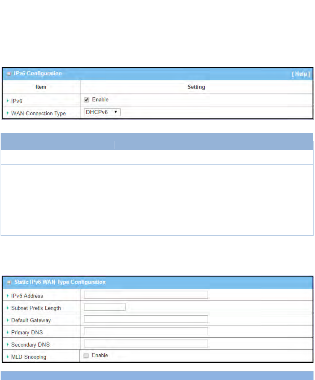
M2MCellularGateway
69
IPv6ConfigurationSetting
GotoBasicNetwork>IPv6>ConfigurationTab.
TheIPv6ConfigurationsettingallowsusertosettheIPv6connectiontypetoaccesstheIPv6network.
IPv6Configuration
Item Valuesetting Description
IPv6 Theboxisunchecked
bydefault, ChecktheEnableboxtoactivatetheIPv6function.
WANConnection
Type
1.Onlycanbe
selectedwhenIPv6
Enable
2.AMustfilledsetting
DefinetheselectedIPv6WANConnectionTypetoestablishtheIPv6
connectivity.
SelectStaticIPv6whenyourISPprovidesyouwithasetIPv6addresses.Thengo
toStaticIPv6WANTypeConfiguration.
SelectDHCPv6whenyourISPprovidesyouwithDHCPv6services.
SelectPPPoEv6whenyourISPprovidesyouwithPPPoEv6accountsettings.
SelectIPv6whenyouwanttouseIPv6connection.
Note:Fortheproductsjusthaving3G/4GWANinterface,onlyIPv6issupported.
StaticIPv6WANTypeConfiguration
StaticIPv6WANTypeConfiguration
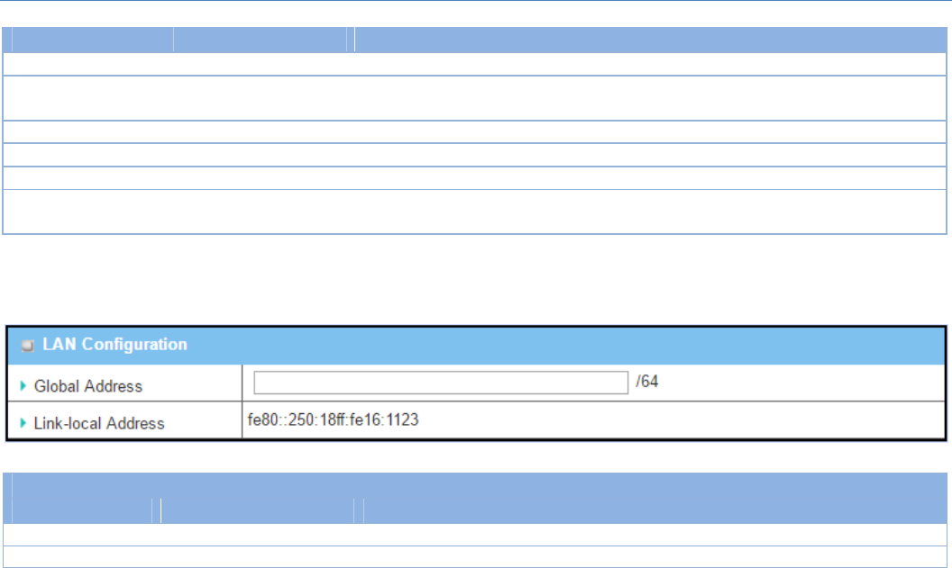
M2MCellularGateway
70
Item Valuesetting Description
IPv6Address AMustfilledsetting EntertheWANIPv6Address fortherouter.
SubnetPrefix
Length AMustfilledsetting EntertheWANSubnetPrefixLengthfortherouter.
DefaultGateway AMustfilledsetting EntertheWANDefaultGateway IPv6address.
PrimaryDNS Anoptionalsetting EntertheWANprimaryDNSServer.
SecondaryDNS Anoptionalsetting EntertheWANsecondaryDNSServer.
MLDSnooping Theboxisunchecked
bydefault Enable/DisabletheMLDSnoopingfunction
LANConfiguration
LANConfiguration
Item Valuesetting Description
GlobalAddress AMustfilledsetting EntertheLANIPv6Address fortherouter.
Link‐localAddress Valueauto‐created Showthelink‐localaddressforLANinterfaceofrouter.
ThengotoAddressAuto‐configuration(summary)forsettingLANenvironment.
Ifabovesettingisconfigured,clicktheSavebuttontosavetheconfiguration,andclicktheRebootbuttonto
reboottherouter.
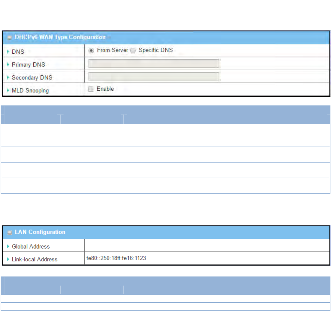
M2MCellularGateway
71
DHCPv6WANTypeConfiguration
DHCPv6WANTypeConfiguration
Item Valuesetting Description
DNS
Theoption[From
Server]isselectedby
default
Selectthe[SpecificDNS]optiontoactivePrimaryDNSandSecondaryDNS.Then
filltheDNSinformation.
PrimaryDNS Cannotmodifiedby
default EntertheWANprimaryDNSServer.
SecondaryDNS Cannotmodifiedby
default EntertheWANsecondaryDNSServer.
MLD Theboxisunchecked
bydefault Enable/DisabletheMLDSnoopingfunction
LANConfiguration
LANConfiguration
Item Valuesetting Description
GlobalAddress Valueauto‐created EntertheLANIPv6Address fortherouter.
Link‐localAddress Valueauto‐created Showthelink‐localaddressforLANinterfaceofrouter.
ThengotoAddressAuto‐configuration(summary)forsettingLANenvironment.
Ifabovesettingisconfigured,clicktheSave button to save the configuration, and click Reboot button to
reboottherouter.
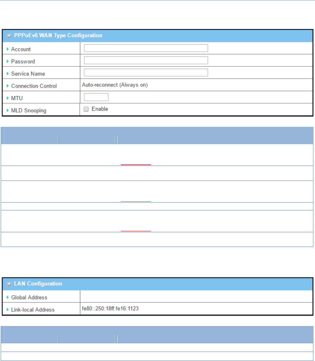
M2MCellularGateway
72
PPPoEv6WANTypeConfiguration
PPPoEv6WANTypeConfiguration
Item Valuesetting Description
Account AMustfilledsetting
EntertheAccountforsettingupPPPoEv6connection.Ifyouwantmore
information,pleasecontactyourISP.
ValueRange:0~45characters.
Password AMustfilledsetting EnterthePasswordforsettingupPPPoEv6connection.Ifyouwantmore
information,pleasecontactyourISP.
ServiceName AMustfilled
setting/Option
EntertheServiceNameforsettingupPPPoEv6connection.Ifyouwantmore
information,pleasecontactyourISP.
ValueRange:0~45characters.
ConnectionControl Fixedvalue ThevalueisAuto‐reconnect(Alwayson).
MTU AMustfilledsetting
EntertheMTUforsettingupPPPoEv6connection.Ifyouwantmore
information,pleasecontactyourISP.
ValueRange:1280~1492.
MLDSnooping Theboxisunchecked
bydefault Enable/DisabletheMLDSnoopingfunction
LANConfiguration
LANConfiguration
Item Valuesetting Description
GlobalAddress Valueauto‐created TheLANIPv6Addressfortherouter.
Link‐localAddress Valueauto‐created Showthelink‐localaddressforLANinterfaceofrouter.
ThengotoAddressAuto‐configuration(summary)forsettingLANenvironment.
Ifabovesettingisconfigured,clickthesavebuttontosavetheconfigurationandclickrebootbuttontoreboot
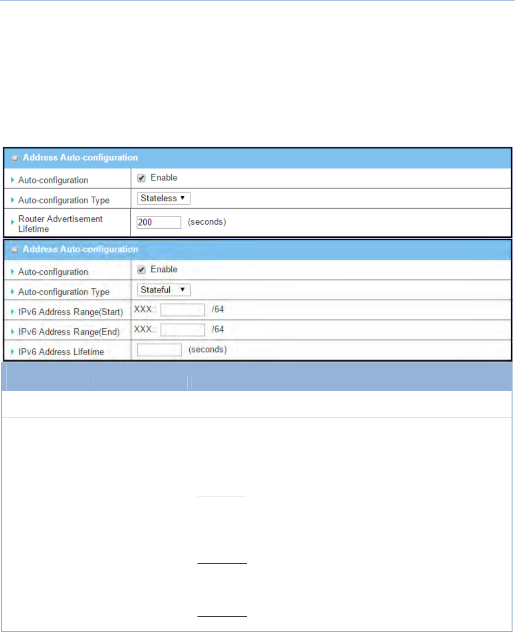
M2MCellularGateway
73
therouter.
ThengotoAddressAuto‐configuration(summary)forsettingLANenvironment.
Ifabovesettingisconfigured,clickthesavebuttontosavetheconfigurationandclickrebootbuttontoreboot
therouter.
AddressAuto‐configuration
AddressAuto‐configuration
Item Valuesetting Description
Auto‐configuration Theboxisunchecked
bydefault ChecktoenabletheAutoconfigurationfeature.
Auto‐configuration
Type
1.Onlycanbe
selectedwhenAuto‐
configurationenabled
2.Statelessisselected
bydefault
DefinetheselectedIPv6WANConnectionTypetoestablishtheIPv6
connectivity.
SelectStatelesstomanagetheLocalAreaNetworktobeSLAAC+RDNSS
RouterAdvertisementLifetime(AMustfilledsetting):EntertheRouter
AdvertisementLifetime(inseconds).200issetbydefault.
ValueRange:0~65535.
SelectStatefultomanagetheLocalAreaNetworktobeStateful(DHCPv6).
IPv6AddressRange(Start)(AMustfilledsetting):EnterthestartIPv6Address
fortheDHCPv6rangeforyourlocalcomputers.0100issetbydefault.
ValueRange:0001~FFFF.
IPv6AddressRange(End)(AMustfilledsetting):EntertheendIPv6Addressfor
theDHCPv6rangeforyourlocalcomputers.0200issetbydefault.
ValueRange:0001~FFFF.

M2MCellularGateway
74
IPv6AddressLifetime(AMustfilledsetting):EntertheDHCPv6lifetimeforyour
localcomputers.36000issetbydefault.
ValueRange:0~65535.
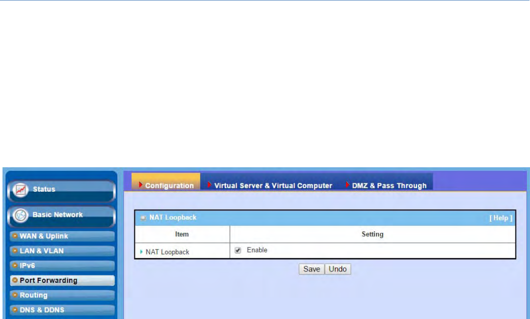
M2MCellularGateway
75
2.5 PortForwarding
Network address translation (NAT) is a methodology of remapping one IP address space into another by
modifying network address information in Internet Protocol (IP) datagram packet headers while they are in
transit across a traffic routing device. The technique was originally used for ease of rerouting traffic in IP
networks without renumbering every host. It has become a popular and essential tool in conserving global
addressspaceallocationsinfaceofIPv4addressexhaustion.Theproductyoupurchasedembedsandactivates
theNATfunction.YoualsocandisabletheNATfunctionin[BasicNetwork]‐[WAN&Uplink]‐[InternetSetup]‐
[WANTypeConfiguration]page.
UsuallyalllocalhostsorserversbehindcorporategatewayareprotectedbyNATfirewall.NATfirewallwillfilter
outunrecognizedpacketstoprotectyourIntranet.So,all localhostsareinvisibletotheoutsideworld.Port
forwarding or port mapping is function that redirects a communication request from one address and port
number combination to assigned one. This technique is most commonlyusedtomakeservicesonahost
residing on a protected or masqueraded (internal) network available to hosts on the opposite side of the
gateway(externalnetwork),byremappingthedestinationIPaddressandportnumber
ThereareseveraloptionalPortForwardingrelatedfunctionsinthisgateway.TheyareVirtualServer,Virtual
Computer, IP Translation, Special AP & ALG, DMZ and Pass Through, etc. The available functions might be
differentforthepurchasedmodel.
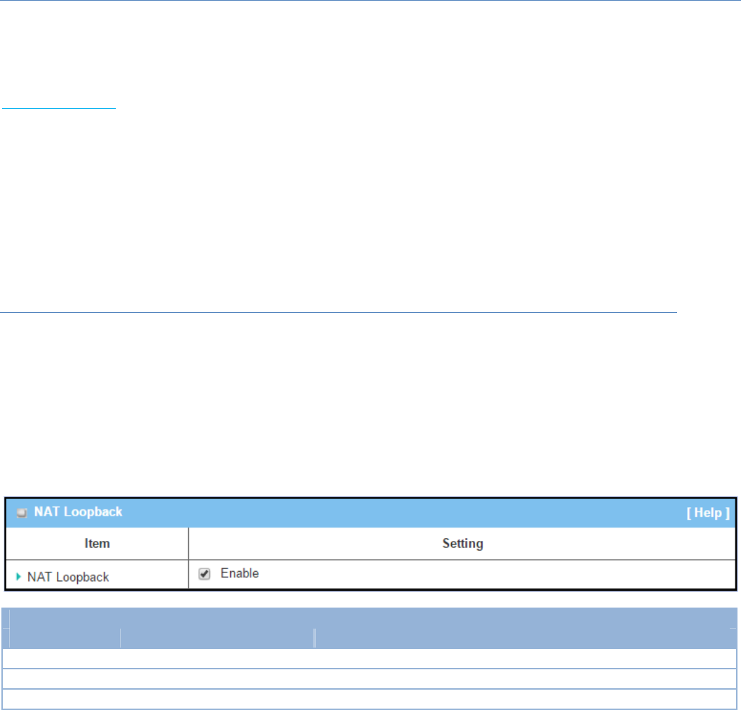
M2MCellularGateway
76
2.5.1Configuration
NATLoopback
ThisfeatureallowsyoutoaccesstheWANglobalIPaddressfromyourinsideNATlocalnetwork.Itisuseful
whenyourunaserverinsideyournetwork.Forexample,ifyousetamailserveratLANside,yourlocal
devicescanaccessthismailserverthroughgateway’sglobalIPaddresswhenenableNATloopbackfeature.On
eithersideareyouinaccessingtheemailserver,attheLANsideorattheWANside,youdon’tneedtochange
theIPaddressofthemailserver.
ConfigurationSetting
GotoBasicNetwork>PortForwarding>Configurationtab.
TheNATLoopbackallowsusertoaccesstheWANIPaddressfrominsideyourlocalnetwork.
EnableNATLoopback
Configuration
Item Valuesetting Description
NATLoopback Theboxischeckedbydefault ChecktheEnableboxtoactivatethisNATfunction
Save N/A ClicktheSavebuttontosavethesettings.
Undo N/A ClicktheUndobuttontocancelthesettings
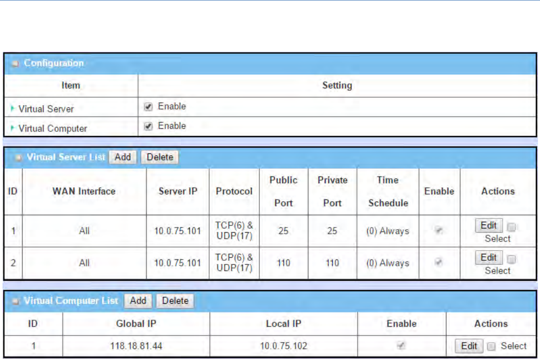
M2MCellularGateway
77
2.5.2VirtualServer&VirtualComputer
There are some important Pot Forwarding functions implemented within the gateway, including "Virtual
Server","NATloopback"and"VirtualComputer".
It is necessary for cooperate staffs who travel outside and want to access various servers behind office
gateway.Youcansetupthoseserversbyusing"VirtualServer" feature. After trip, if want to access those
serversfromLANsidebyglobalIP,withoutchangeoriginalsetting,NATLoopbackcanachieveit.
"Virtualcomputer"isahostbehindNATgatewaywhoseIPaddressisaglobaloneandisvisibletotheoutside
world.SinceitisbehindNAT,itisprotectedbygatewayfirewall.ToconfigureVirtualComputer,youjusthave
tomapthelocalIPofthevirtualcomputertoaglobalIP.
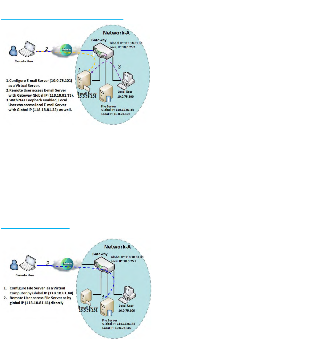
M2MCellularGateway
78
VirtualServer&NATLoopback
"VirtualServer"allowsyoutoaccessserverswiththe
globalIPaddressorFQDNofthegatewayasiftheyare
serversexistedintheInternet.Butinfact,theseservers
arelocatedintheIntranetandarephysicallybehindthe
gateway.Thegatewayservestheservicerequestsbyport
forwardingtherequeststotheLANserversandtransfers
the replies from LAN servers to the requester on the
WANside.Asshowninexample,anE‐mailvirtualserver
isdefinedtobelocatedataserverwithIPaddress
10.0.75.101intheIntranetofNetwork‐A,includingSMTP
service port 25 and POP3 service port 110. So, the
remote user can access the E‐mail server with the
gateway’sglobalIP118.18.81.33fromitsWANside.ButtherealE‐mailserverislocatedatLANsideandthe
gatewayistheportforwarderforE‐mailservice.
NATLoopbackallowsyoutoaccesstheWANglobalIPaddressfromyourinsideNATlocalnetwork.Itisuseful
whenyourunaserverinsideyournetwork.Forexample,ifyousetamailserveratLANside,yourlocal
devicescanaccessthismailserverthroughgateway’sglobalIPaddresswhenenableNATloopbackfeature.On
eithersideareyouinaccessingtheemailserver,attheLANsideorattheWANside,youdon’tneedtochange
theIPaddressofthemailserver.
VirtualComputer
"Virtual Computer" allows you to assign LAN hosts to
globalIPaddresses,sothattheycanbevisibletooutside
world.Whileso,theyarealsoprotectedbythegateway
firewallasbeingclienthostsintheIntranet.Forexample,
ifyousetaFTPfileserveratLANsidewithlocalIP
address10.0.75.102andglobalIPaddress118.18.82.44,
aremoteusercanaccessthefileserverwhileitishidden
behind the NAT gateway. That is because the gateway
takescareofallaccessingtotheIPaddress118.18.82.44,
including to forward the access requests to the file
serverandtosendtherepliesfromtheservertooutside
world.
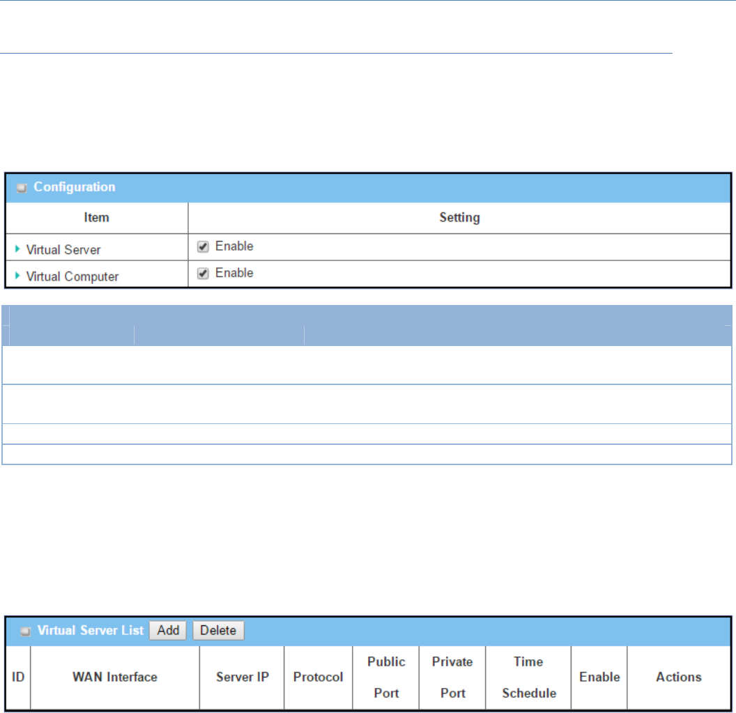
M2MCellularGateway
79
VirtualServer&VirtualComputerSetting
GotoBasicNetwork>PortForwarding>VirtualServer&VirtualComputertab.
EnableVirtualServerandVirtualComputer
Configuration
Item Valuesetting Description
VirtualServer Theboxisuncheckedby
default ChecktheEnableboxtoactivatethisportforwardingfunction
VirtualComputer Theboxischeckedby
default ChecktheEnableboxtoactivatethisportforwardingfunction
Save N/A ClicktheSavebuttontosavethesettings.
Undo N/A ClicktheUndobuttontocancelthesettings.
Create/EditVirtualServer
The gateway allows you to custom your Virtual Server rules. It supports up to a maximumof 20 rule‐based
VirtualServersets.
WhenAddbuttonisapplied,VirtualServerRuleConfigurationscreenwillappear.
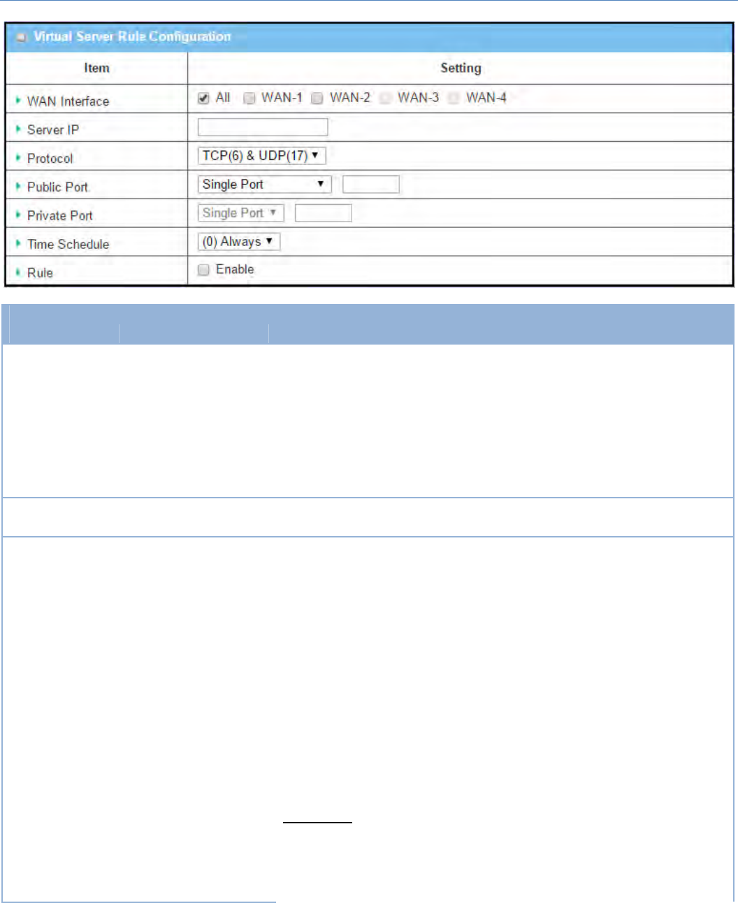
M2MCellularGateway
80
VirtualServerRuleConfiguration
Item Valuesetting Description
WANInterface 1.AMustfilledsetting
2.DefaultisALL.
Definetheselectedinterfacetobethepacket‐enteringinterfaceofthe
gateway.
IfthepacketstobefilteredarecomingfromWAN‐xthenselectWAN‐xforthis
field.
SelectALLforpacketscomingintothegatewayfromanyinterface.
ItcanbeselectedWAN‐xboxwhenWAN‐xenabled.
Note:Theavailablecheckboxes(WAN‐1~WAN‐4)dependonthenumberof
WANinterfacesfortheproduct.
ServerIP AMustfilledsetting ThisfieldistospecifytheIPaddressoftheinterfaceselectedintheWAN
Interfacesettingabove.
Protocol AMustfilledsetting
When“ICMPv4”isselected
Itmeanstheoption“Protocol”ofpacketfilterruleisICMPv4.
ApplyTimeScheduletothisrule,otherwiseleaveitasAlways.(referto
SchedulingsettingunderObjectDefinition)
ThencheckEnableboxtoenablethisrule.
When“TCP”isselected
Itmeanstheoption“Protocol”ofpacketfilterruleisTCP.
PublicPortselectedapredefinedportfromWell‐knownService,andPrivate
PortisthesamewithPublicPortnumber.
PublicPortisselectedSinglePortandspecifyaportnumber,andPrivatePort
canbesetaSinglePortnumber.
PublicPortisselectedPortRangeandspecifyaportrange,andPrivatePort
canbeselectedSinglePortorPortRange.
ValueRange:1~65535forPublicPort,PrivatePort.
When“UDP”isselected
Itmeanstheoption“Protocol”ofpacketfilterruleisUDP.
PublicPortselectedapredefinedportfromWell‐knownService,andPrivate

M2MCellularGateway
81
PortisthesamewithPublicPortnumber.
PublicPortisselectedSinglePortandspecifyaportnumber,andPrivatePort
canbesetaSinglePortnumber.
PublicPortisselectedPortRangeandspecifyaportrange,andPrivatePort
canbeselectedSinglePortorPortRange.
ValueRange:1~65535forPublicPort,PrivatePort.
When“TCP&UDP”isselected
Itmeanstheoption“Protocol”ofpacketfilterruleisTCPandUDP.
PublicPortselectedapredefinedportfromWell‐knownService,andPrivate
PortisthesamewithPublicPortnumber.
PublicPortisselectedSinglePortandspecifyaportnumber,andPrivatePort
canbesetaSinglePortnumber.
PublicPortisselectedPortRangeandspecifyaportrange,andPrivatePort
canbeselectedSinglePortorPortRange.
ValueRange:1~65535forPublicPort,PrivatePort.
When“GRE”isselected
Itmeanstheoption“Protocol”ofpacketfilterruleisGRE.
When“ESP”isselected
Itmeanstheoption“Protocol”ofpacketfilterruleisESP.
When“SCTP”isselected
Itmeanstheoption“Protocol”ofpacketfilterruleisSCTP.
When“User‐defined”isselected
Itmeanstheoption“Protocol”ofpacketfilterruleisUser‐defined.
ForProtocolNumber,enteraportnumber.
TimeSchedule
1.Anoptionalfilledsetting
2.(0)AlwaysIsselectedby
default.
ApplyTimeScheduletothisrule;otherwiseleaveitas(0)Always.(referto
SchedulingsettingunderObjectDefinition)
Rule
1.Anoptionalfilledsetting
2.Theboxisuncheckedby
default.
ChecktheEnableboxtoactivatetherule.
Save N/A ClicktheSavebuttontosavethesettings.
Undo N/A ClicktheUndobuttontocancelthesettings.
Back N/A WhentheBackbuttonisclickedthescreenwillreturntopreviouspage.
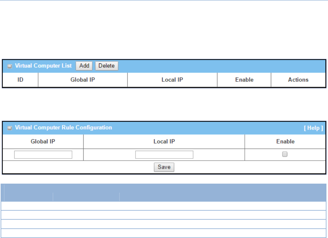
M2MCellularGateway
82
Create/EditVirtualComputer
ThegatewayallowsyoutocustomyourVirtualComputerrules.Itsupportsuptoamaximumof20rule‐based
VirtualComputersets.
WhenAddbuttonisapplied,VirtualComputerRuleConfigurationscreenwillappear.
VirtualComputerRuleConfiguration
Item Valuesetting Description
GlobalIP AMustfilledsetting ThisfieldistospecifytheIPaddressoftheWANIP.
LocalIP AMustfilledsetting ThisfieldistospecifytheIPaddressoftheLANIP.
Enable N/A ThencheckEnableboxtoenablethisrule.
Save N/A ClicktheSavebuttontosavethesettings.
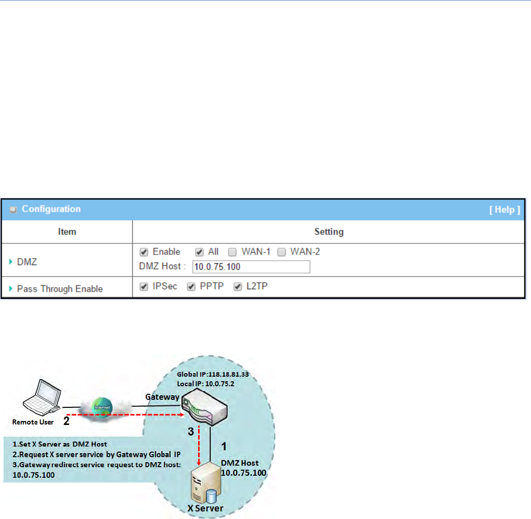
M2MCellularGateway
83
2.5.3DMZ&PassThrough
DMZ (De Militarized Zone) Host is a host that is exposed to the Internet cyberspace but still within the
protectionoffirewallbygatewaydevice.So,thefunctionallowsacomputertoexecute2‐waycommunication
for Internet games, Video conferencing, Internet telephony and other special applications. In some cases
whenaspecificapplicationisblockedbyNATmechanism,youcanindicatethatLANcomputerasaDMZhost
tosolvethisproblem.
TheDMZfunctionallowsyoutoaskthegatewaypassthroughallnormalpacketstotheDMZhostbehindthe
NATgatewayonlywhenthesepacketsarenotexpectedtoreceivebyapplicationsinthegatewayorbyother
clienthostsintheIntranet.Certainly,theDMZhostisalsoprotected by the gateway firewall. Activate the
featureandspecifytheDMZhostwithahostintheIntranetwhenneeded.
DMZScenario
Whenthenetworkadministratorwantstosetup
some service daemons in a host behind NAT
gatewaytoallowremoteusersrequestforservices
fromserveractively,youjusthavetoconfigurethis
hostasDMZHost.Asshowninthediagram,there
is an X server installed as DMZ host, whose IP
address is 10.0.75.100. Then, remote user can
requestservicesfromXserverjustasitisprovided
by the gateway whose global IP address is
118.18.81.33. The gateway will forward those
packets, not belonging to any configured virtual
serverorapplications,directlytotheDMZhost.
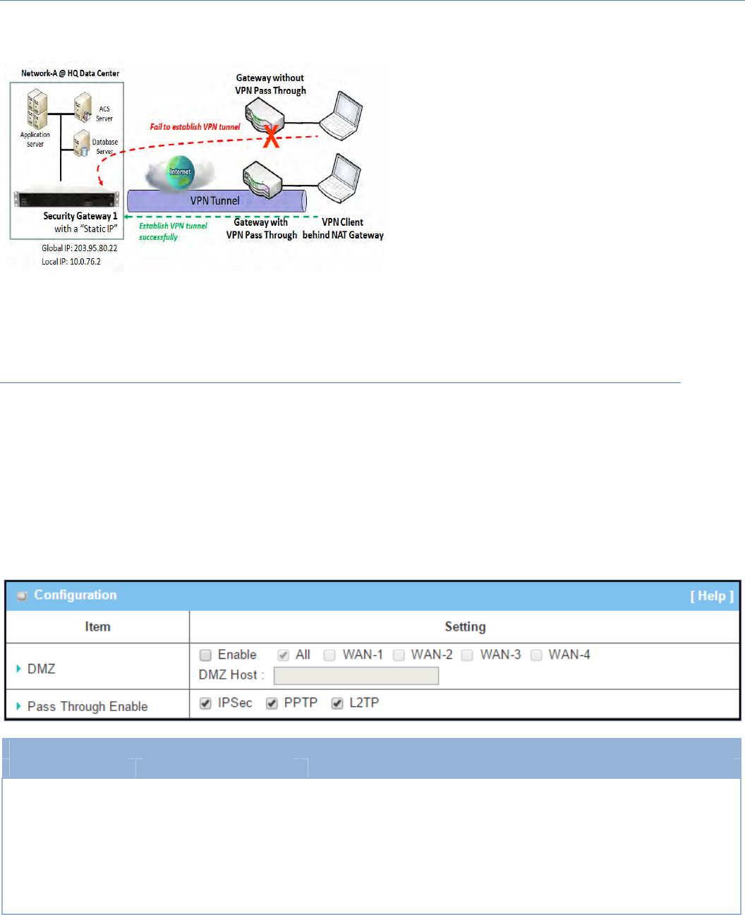
M2MCellularGateway
84
VPNPassthroughScenario
Since VPN traffic is different from that of TCP or
UDPconnection,itwillbeblockedbyNATgateway.
TosupportthepassthroughfunctionfortheVPN
connectionsinitiatingfromVPNclientsbehindNAT
gateway,thegatewaymustimplementsomekind
ofVPNpassthroughfunctionforsuchapplication.
Thegatewaysupportthepassthroughfunctionfor
IPSec, PPTP, and L2TP connections, you just have
tocheckthecorrespondingcheckboxtoactivateit.
DMZ&PassThroughSetting
GotoBasicNetwork>PortForwarding>DMZ&PassThroughtab.
TheDMZhostisahostthatisexposedtotheInternetcyberspacebutstillwithintheprotectionoffirewallby
gatewaydevice.
EnableDMZandPassThrough
Configuration
Item Valuesetting Description
DMZ 1.AMustfilledsetting2.
DefaultisALL.
ChecktheEnableboxtoactivatetheDMZfunction
Definetheselectedinterfacetobethepacket‐enteringinterfaceofthe
gateway,andfillintheIPaddressofHostLANIPinDMZHostfield
.
IfthepacketstobefilteredarecomingfromWAN‐xthenselectWAN‐xfor
thisfield.
SelectALLforpacketscomingintotherouterfromanyinterfaces.

M2MCellularGateway
85
ItcanbeselectedWAN‐xboxwhenWAN‐xenabled.
Note:Theavailablecheckboxes(WAN‐1~WAN‐4)dependonthenumber
ofWANinterfacesfortheproduct.
PassThroughEnable Theboxesarecheckedby
default
ChecktheboxtoenablethepassthroughfunctionfortheIPSec,PPTP,and
L2TP.
Withthepassthroughfunctionenabled,theVPNhostsbehindthegateway
stillcanconnecttoremoteVPNservers.
Save N/A ClicktheSavebuttontosavethesettings.
Undo N/A ClicktheUndobuttontocancelthesettings
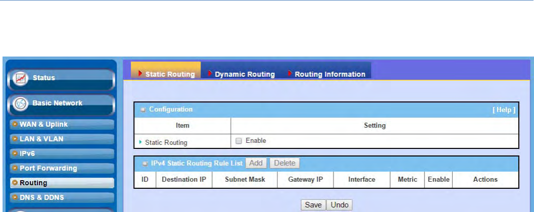
M2MCellularGateway
86
2.6Routing
Ifyouhavemorethanonerouterandsubnet,youwillneedtoenableroutingfunctiontoallowpacketstofind
proper routing path and allow different subnets to communicate with each other. Routing is the process of
selectingbestpathsinanetwork.Itisperformedformanykindsof networks,likeelectronicdatanetworks
(suchastheInternet),byusingpacketswitchingtechnology.Theroutingprocessusuallydirectsforwardingon
the basis of routing tables which maintain a record of the routes to various network destinations. Thus,
constructingroutingtables,whichareheldintherouter'smemory,isveryimportantforefficientrouting.Most
routingalgorithmsuseonlyonenetworkpathatatime.
The routing tables record your pre‐defined routing paths for some specific destination subnets. It is static
routing.However,ifthecontentsofroutingtablesrecordtheobtainedroutingpathsfromneighborroutersby
usingsomeprotocols,suchasRIP,OSPFandBGP.Itisdynamicrouting.Thesebothroutingapproacheswillbe
illustrated one after one. In addition, the gateway also built in one advanced configurable routing software
Quaggaformorecomplexroutingapplications,youcanconfigureitifrequiredviaTelnetCLI.
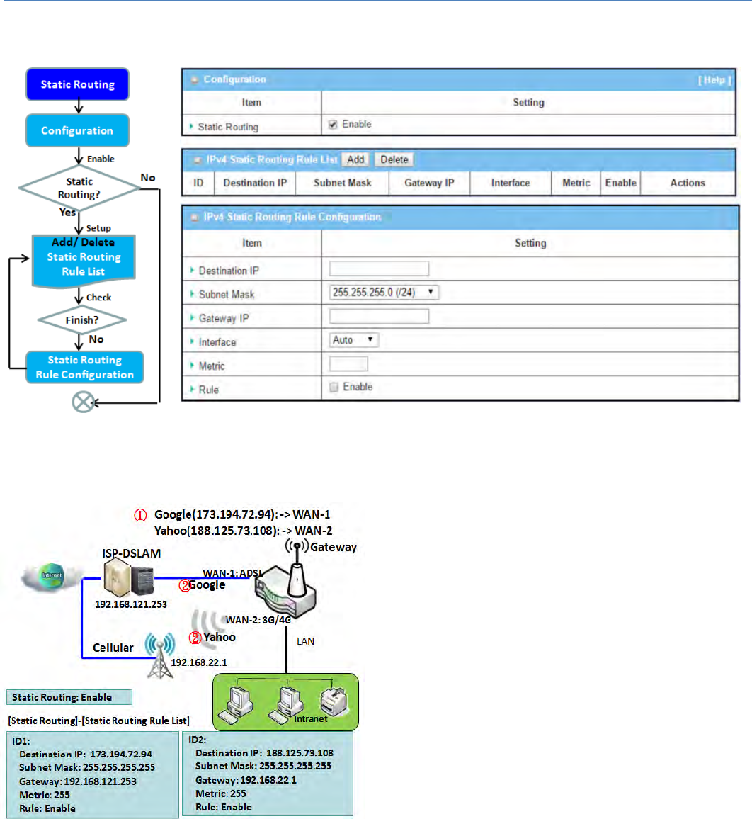
M2MCellularGateway
87
2.6.1StaticRouting
"Static Routing" function lets you define the routing paths for some dedicated hosts/servers or subnets to store
in the routing table of the gateway. The gateway routes incoming packets to different peer gateways based on
the routing table. You need to define the static routing information in gateway routing rule list.
When the administrator of the gateway wants to
specify what kinds of packets to be transferred via
which gateway interface and which peer gateway to
theirdestination.Itcanbecarriedoutbythe"Static
Routing" feature. Dedicated packet flows from the
Intranetwillberoutedtotheirdestinationviathepre‐
defined peer gateway and corresponding gateway
interfacethataredefinedinthesystemroutingtable
bymanual.
As shown in the diagram, when the destination is
Googleaccess,rule1setinterfaceasADSL,routing
gatewayasIP‐DSLAMgateway192.168.121.253.Allthe
packets to Google will go through WAN‐1. And the
samewayappliedtorule2ofaccessYahoo.Rule2sets
3G/4Gasinterface.
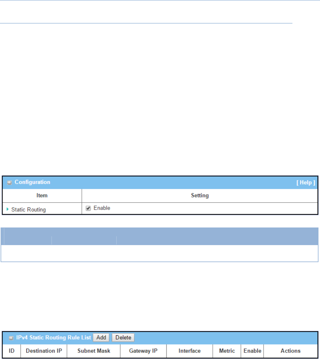
M2MCellularGateway
88
StaticRoutingSetting
GotoBasicNetwork>Routing>StaticRoutingTab.
There are three configuration windows for static routing feature, including "Configuration", "Static Routing
Rule List" and "Static Routing Rule Configuration" windows. "Configuration" window lets you activate the
globalstaticroutingfeature.Eventherearealreadyroutingrules,ifyouwanttodisableroutingtemporarily,
justunchecktheEnableboxtodisableit."StaticRoutingRuleList"windowlistsallyourdefinedstaticrouting
rule entries. Using "Add" or "Edit" button to add and create one new static routing rule or to modify an
existedone.
When"Add"or"Edit"buttonisapplied,the"StaticRoutingRuleConfiguration"windowwillappeartoletyou
defineastaticroutingrule.
EnableStaticRouting
JustchecktheEnableboxtoactivatethe"StaticRouting"feature.
StaticRouting
Item Valuesetting Description
StaticRouting Theboxisuncheckedby
default ChecktheEnableboxtoactivatethisfunction
Create/EditStaticRoutingRules
TheStaticRoutingRuleListshowsthesetupparametersofallstaticroutingruleentries.Toconfigureastatic
routing rule, you must specify related parameters including the destination IP address and subnet mask of
dedicatedhost/serverorsubnet,theIPaddressofpeergateway,themetricandtheruleactivation.
Thegatewayallowsyoutocustomyourstaticroutingrules.Itsupportsuptoamaximumof64rulesets.When
Addbuttonisapplied,StaticRoutingRuleConfigurationscreenwillappear,whiletheEditbuttonattheend
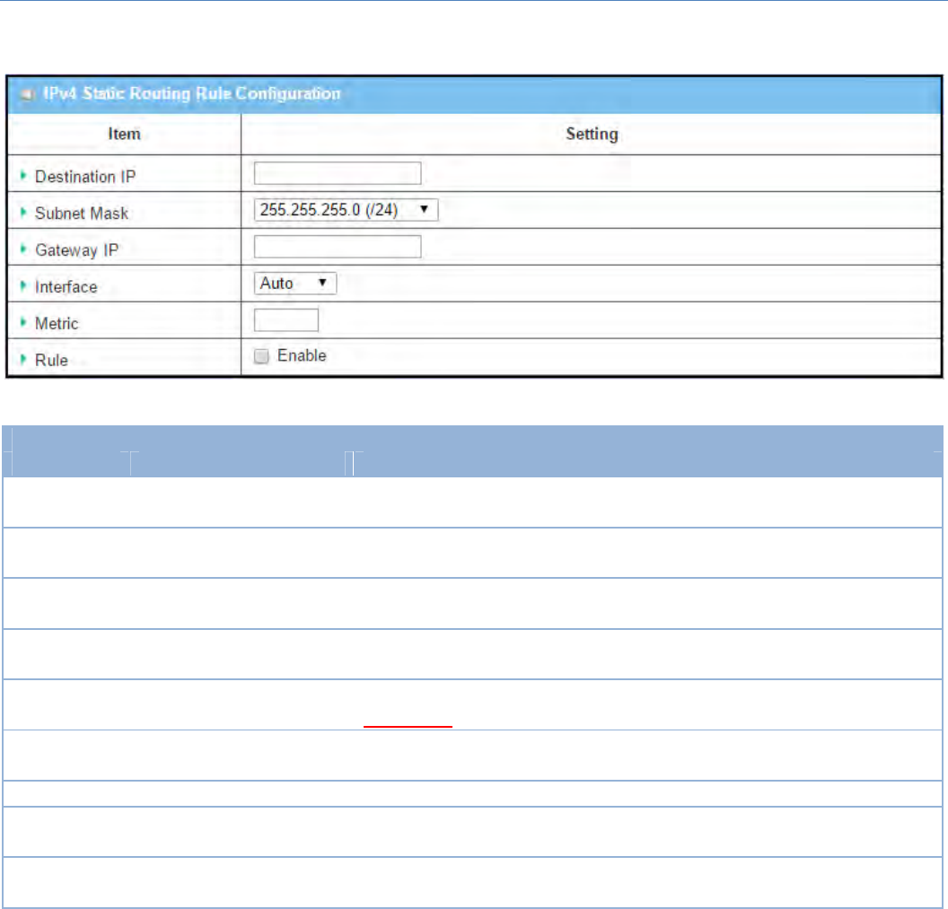
M2MCellularGateway
89
ofeachstaticroutingrulecanletyoumodifytherule.
IPv4StaticRouting
Item Valuesetting Description
DestinationIP 1.IPv4Format
2.AMustfilledsetting SpecifytheDestinationIPofthisstaticroutingrule.
SubnetMask 255.255.255.0(/24)issetby
default SpecifytheSubnetMaskofthisstaticroutingrule.
GatewayIP 1.IPv4Format
2.AMustfilledsetting SpecifytheGatewayIPofthisstaticroutingrule.
Interface Autoissetbydefault SelecttheInterfaceofthisstaticroutingrule.ItcanbeAuto,ortheavailable
WAN/LANinterfaces.
Metric 1.NumbericStringFormat
2.AMustfilledsetting
TheMetricofthisstaticroutingrule.
ValueRange:0~255.
Rule Theboxisuncheckedby
default. ClickEnableboxtoactivatethisrule.
Save NA ClicktheSavebuttontosavetheconfiguration
Undo NA ClicktheUndobuttontorestorewhatyoujustconfiguredbacktotheprevious
setting.
Back NA WhentheBackbuttonisclickedthescreenwillreturntotheStaticRouting
Configurationpage.
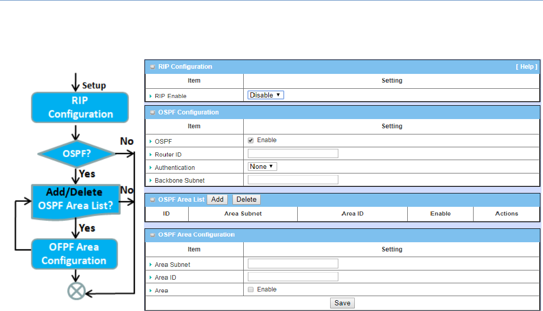
M2MCellularGateway
90
2.6.2DynamicRouting
DynamicRouting,alsocalledadaptiverouting,describesthecapabilityofasystem,throughwhichroutesare
characterizedbytheirdestination,toalterthepaththattheroutetakesthroughthesysteminresponsetoa
changeinnetworkconditions.
Thisgatewaysupportsdynamicroutingprotocols,includingRIPv1/RIPv2(RoutingInformationProtocol),and
OSPF(OpenShortestPathFirst),foryoutoestablishroutingtable automatically. The feature of dynamic
routingwillbeveryusefulwhentherearelotsofsubnetsinyournetwork.Generallyspeaking,RIPissuitable
forsmallnetwork.OSPFismoresuitableformediumnetwork.
Thesupporteddynamicroutingprotocolsaredescribedasfollows.
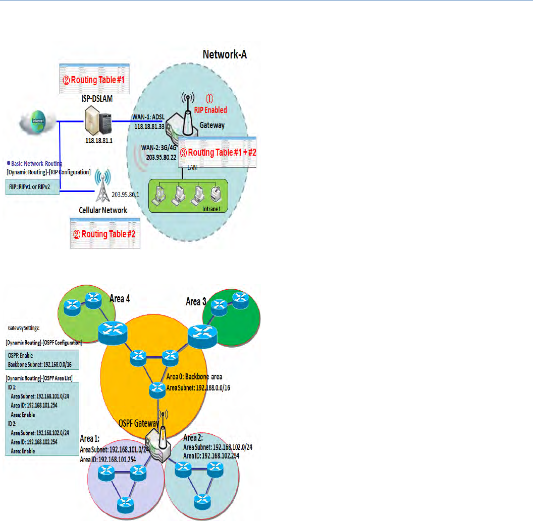
M2MCellularGateway
91
RIPScenario
The Routing Information Protocol (RIP) is one of the
oldest distance‐vector routing protocols, which
employs the hop count as a routing metric. RIP
preventsroutingloopsbyimplementingalimitonthe
numberofhopsallowedinapathfromthesourcetoa
destination. The maximum number of hops allowed
for RIP is 15. This hop limit, however, also limits the
sizeofnetworksthatRIPcansupport.Ahopcountof
16 is considered an infinite distance, in other words
the route is considered unreachable. RIP implements
the split horizon, route poisoning and hold‐down
mechanisms to prevent incorrect routing information
frombeingpropagated.
OSPFScenario
OpenShortestPathFirst(OSPF)isaroutingprotocol
that uses link state routing algorithm. It is the most
widelyusedinteriorgatewayprotocol(IGP)inlarge
enterprise networks. It gathers link state information
fromavailableroutersandconstructsatopologymap
ofthenetwork.Thetopologyispresentedasarouting
table which routes datagrams based solely on the
destinationIPaddress.
Network administrator can deploy OSPF gateway in
largeenterprisenetworktogetitsroutingtablefrom
theenterprisebackbone,andforwardrouting
information to other routers, which are no linked to
theenterprisebackbone.Usually,anOSPFnetworkis
subdivided into routing areas to simplify
administration and optimize traffic and resource
utilization.
Asshowninthediagram,OSPFgatewaygathersroutinginformationfromthebackbonegatewaysinarea0,
andwillforwarditsroutinginformationtotheroutersinarea1andarea2whicharenotinthebackbone.
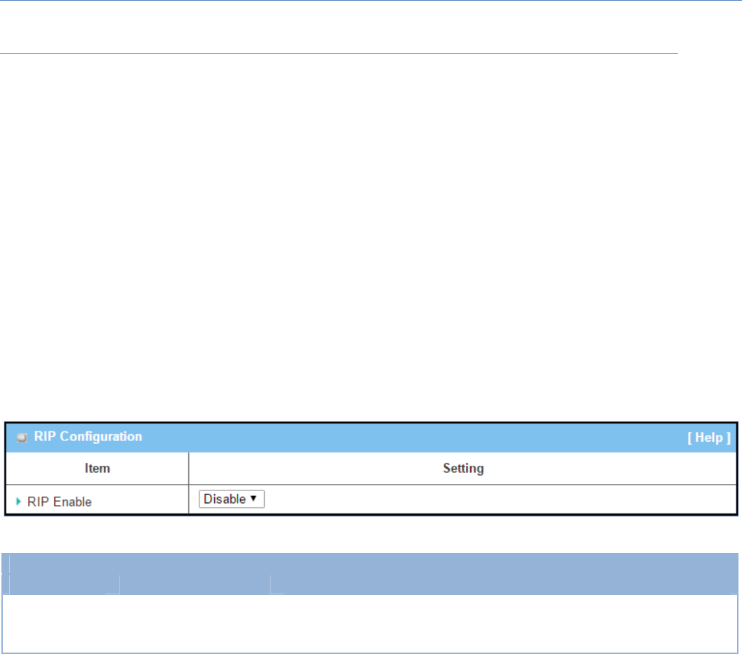
M2MCellularGateway
92
DynamicRoutingSetting
GotoBasicNetwork>Routing>DynamicRoutingTab.
Thedynamicroutingsetting allows user to customize RIP, and OSPFprotocolsthroughtherouterbasedon
theirofficesetting.
Inthe"DynamicRouting"page,thereareseveralconfigurationwindowsfordynamicroutingfeature.Theyare
the "RIP Configuration" window, "OSPF Configuration" window, "OSPF Area List", and "OSPF Area
Configuration"window.RIP,andOSPFprotocolscanbeconfiguredindividually.
The"RIPConfiguration"window letsyouchoosewhichversionofRIPprotocoltobeactivatedordisableit.
The "OSPF Configuration" window can let you activate the OSPF dynamic routing protocol and specify its
backbonesubnet.Moreover,the"OSPFAreaList"windowlistsalldefinedareasintheOSPFnetwork.
RIPConfiguration
TheRIPconfigurationsettingallowsusertocustomizeRIPprotocolthroughtherouterbasedontheiroffice
setting.
RIPConfiguration
Item Valuesetting Description
RIPEnable Disableissetbydefault
SelectDisablewilldisableRIPprotocol.
SelectRIPv1willenableRIPv1protocol.
SelectRIPv2willenableRIPv2protocol.
OSPFConfiguration
TheOSPFconfigurationsettingallowsusertocustomizeOSPFprotocol through the router based on their
officesetting.
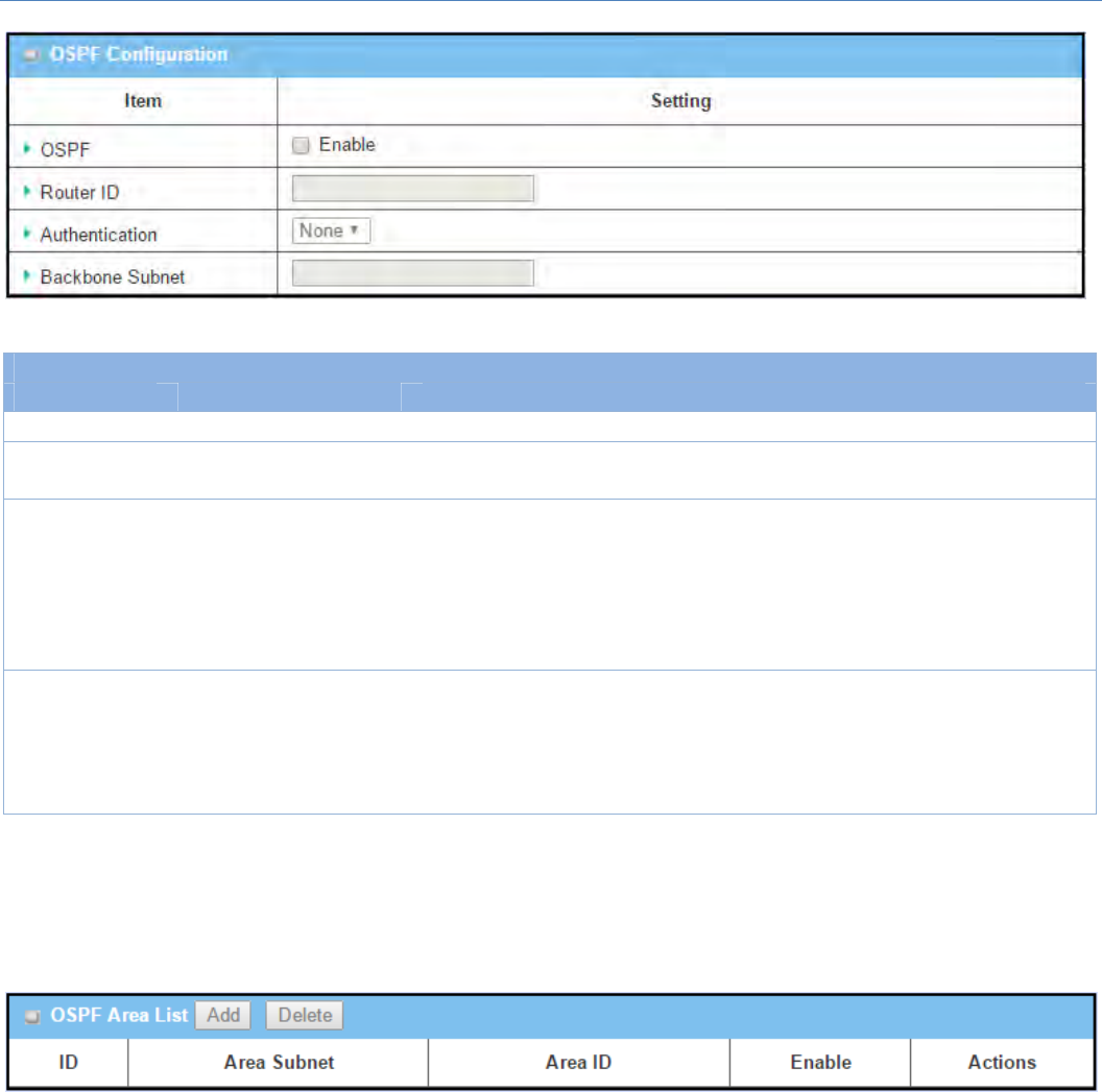
M2MCellularGateway
93
OSPFConfiguration
Item Valuesetting Description
OSPF Disableissetbydefault ClickEnableboxtoactivatetheOSPFprotocol.
RouterID 1.IPv4Format
2.AMustfilledsetting TheRouterIDofthisrouteronOSPFprotocol
Authentication Noneissetbydefault
TheAuthenticationmethodofthisrouteronOSPFprotocol.
SelectNonewilldisableAuthenticationonOSPFprotocol.
SelectTextwillenableTextAuthenticationwithenteredtheKeyinthisfieldon
OSPFprotocol.
SelectMD5willenableMD5AuthenticationwithenteredtheIDandKeyin
thesefieldsonOSPFprotocol.
Backbone
Subnet
1.ClasslessInterDomain
Routing(CIDR)Subnet
MaskNotation.(Ex:
192.168.1.0/24)
2.AMustfilledsetting
TheBackboneSubnetofthisrouteronOSPFprotocol.
Create/EditOSPFAreaRules
ThegatewayallowsyoutocustomyourOSPFAreaListrules.Itsupportsuptoamaximumof32rulesets.
WhenAddbuttonisapplied,OSPFAreaRuleConfigurationscreenwillappear.
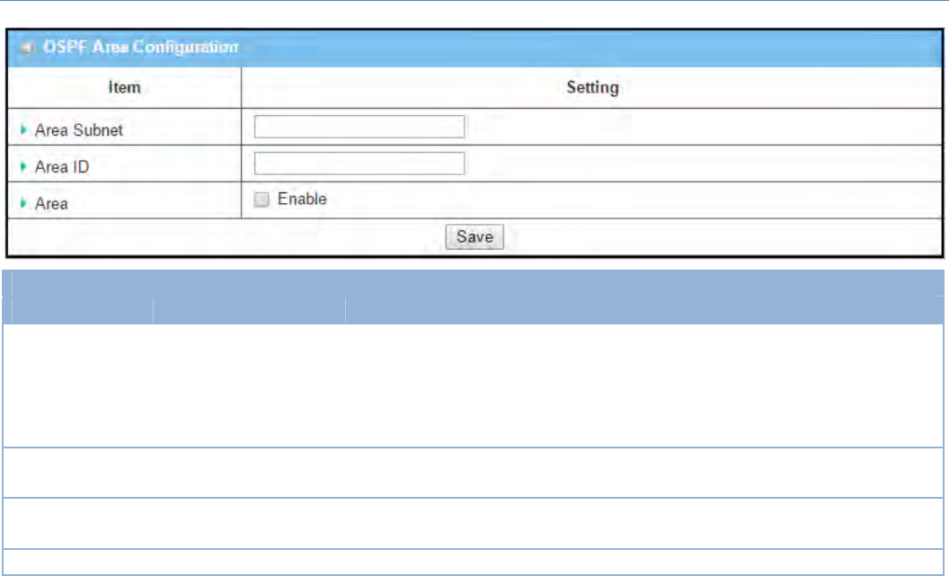
M2MCellularGateway
94
OSPFAreaConfiguration
Item Valuesetting Description
AreaSubnet
1.ClasslessInterDomain
Routing(CIDR)Subnet
MaskNotation.(Ex:
192.168.1.0/24)
2.AMustfilledsetting
TheAreaSubnetofthisrouteronOSPFAreaList.
AreaID 1.IPv4Format
2.AMustfilledsetting TheAreaIDofthisrouteronOSPFAreaList.
Area Theboxisuncheckedby
default. ClickEnableboxtoactivatethisrule.
Save N/A ClicktheSavebuttontosavetheconfiguration
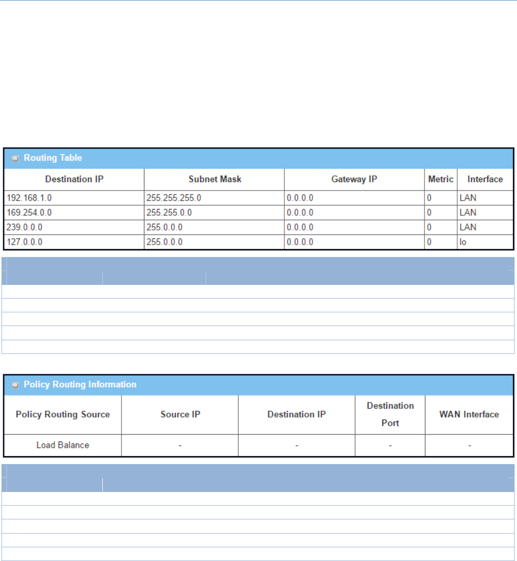
M2MCellularGateway
95
2.6.3RoutingInformation
Theroutinginformationallowsusertoviewtheroutingtableandpolicyroutinginformation.PolicyRouting
InformationisonlyavailablewhentheLoadBalancefunctionisenabledandtheLoadBalanceStrategyisBy
UserPolicy.
GotoBasicNetwork>Routing>RoutingInformationTab.
RoutingTable
Item Valuesetting Description
DestinationIP N/A RoutingrecordofDestinationIP.IPv4Format.
SubnetMask N/A RoutingrecordofSubnetMask.IPv4Format.
GatewayIP N/A RoutingrecordofGatewayIP.IPv4Format.
Metric N/A RoutingrecordofMetric.NumericStringFormat.
Interface N/A RoutingrecordofInterfaceType.StringFormat.
PolicyRoutingInformation
Item Valuesetting Description
PolicyRoutingSource N/A PolicyRoutingofSource.StringFormat.
SourceIP N/A PolicyRoutingofSourceIP.IPv4Format.
DestinationIP N/A PolicyRoutingofDestinationIP.IPv4Format.
DestinationPort N/A PolicyRoutingofDestinationPort.StringFormat.
WANInterface N/A PolicyRoutingofWANInterface.StringFormat.
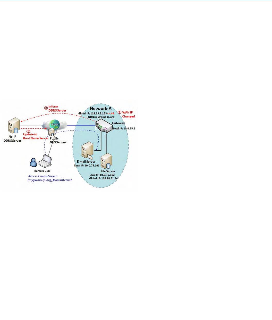
M2MCellularGateway
96
2.7 DNS&DDNS
HowdoesuseraccessyourserverifyourWANIPaddresschangesallthetime?Onewayistoregisteranew
domainname,andmaintainyourownDNSserver.Anothersimplerwayistoapplyadomainnametoathird‐
partyDDNSserviceprovider.Theservicecanbefreeorcharged.Ifyouwanttounderstandthebasicconcepts
ofDNSandDynamicDNS,youcanrefertoWikipediawebsite7,8.
2.7.1DNS&DDNSConfiguration
DynamicDNS
TohostyourserveronachangingIPaddress,you
have to use dynamic domain name service (DDNS).
Therefore, anyone wishing to reach your host only
needstoknowthedomainname.DynamicDNSwill
mapthenameofyourhosttoyourcurrentIP
address,whichchangeseachtimeyouconnectyour
Internetserviceprovider.
TheDynamicDNSserviceallowsthegatewaytoalias
apublicdynamicIPaddresstoastaticdomainname,
allowingthegatewaytobemoreeasilyaccessed
fromvariouslocationsontheInternet.Asshownin
thediagram,userregisteredadomainnametoa
third‐party DDNS service provider (NO‐IP) to use DDNS function. OncetheIPaddressofdesignatedWAN
interfacehaschanged,thedynamicDNSagentinthegatewaywill inform the DDNS server withthe new IP
address.Theserverautomaticallyre‐mapsyourdomainnamewiththechangedIPaddress.So,otherhostsor
remoteusersintheInternetworldareabletolinktoyourgatewaybyusingyourdomainnameregardlessof
thechangingglobalIPaddress.
7http://en.wikipedia.org/wiki/Domain_Name_System
8http://en.wikipedia.org/wiki/Dynamic_DNS
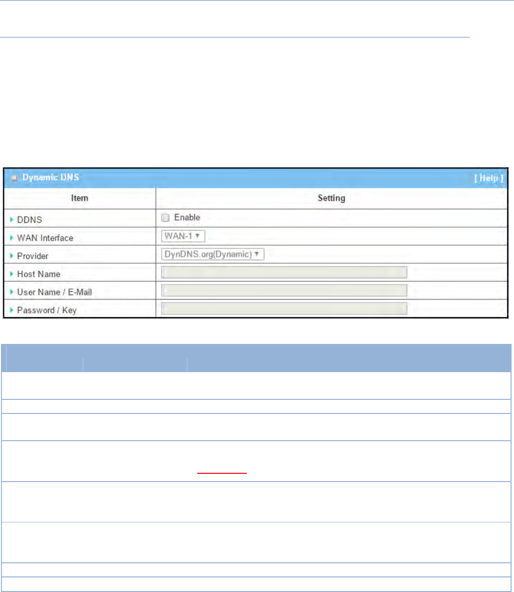
M2MCellularGateway
97
DNS&DDNSSetting
GotoBasicNetwork>DNS&DDNS>ConfigurationTab.
TheDNS&DDNSsettingallowsusertosetupDynamicDNSfeatureandDNSredirectrules.
SetupDynamicDNS
ThegatewayallowsyoutocustomyourDynamicDNSsettings.
DDNS(DynamicDNS)Configuration
Item Valuesetting Description
DDNS Theboxisuncheckedby
default ChecktheEnableboxtoactivatethisfunction.
WANInterface WAN1issetbydefault SelecttheWANInterfaceIPAddressofthegateway.
Provider DynDNS.org(Dynamic)is
setbydefault
SelectyourDDNSproviderofDynamicDNS.ItcanbeDynDNS.org(Dynamic),
DynDNS.org(Custom),NO‐IP.com,etc...
HostName
1.Stringformatcanbeany
text
2.AMustfilledsetting
YourregisteredhostnameofDynamicDNS.
ValueRange:0~63characters.
UserName/E‐
Mail
1.Stringformatcanbeany
text
2.AMustfilledsetting
EnteryourUsernameorE‐mailaddresssofDynamicDNS.
Password/Key
1.Stringformatcanbeany
text
2.AMustfilledsetting
EnteryourPasswordorKeyofDynamicDNS.
Save N/A ClickSavetosavethesettings
Undo N/A ClickUndotocancelthesettings
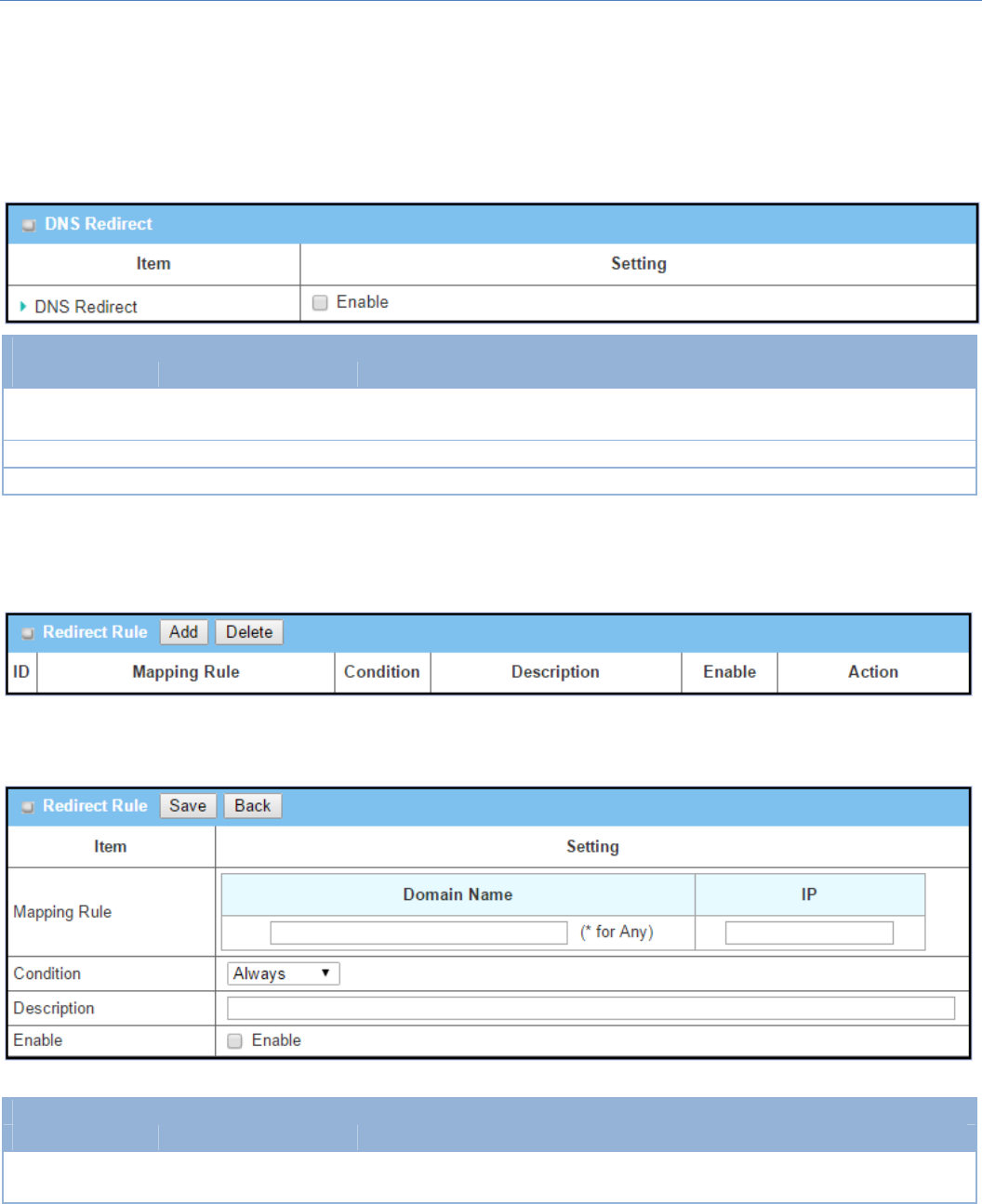
M2MCellularGateway
98
SetupDNSRedirect
DNSredirectisaspecialfunctiontoredirectcertaintrafficstoaspecifiedhost.Administatorcanmanagethe
internet/intranettrafficsthataregoingtoaccesssomerestrictedDNSandforcethosetrafficstoberedirected
toaspecifiedhost.
DNSRedirectConfiguration
Item Valuesetting Description
DNSRedirect Theboxisuncheckedby
default ChecktheEnableboxtoactivatethisfunction.
Save N/A ClickSavetosavethesettings
Undo N/A ClickUndotocancelthesettings
IfyouenabledtheDNSRedirectfunction,youhavetofurtherspecifytheredirectrules.Accordingtotherules,
thegatewaycanredirectthetrafficthatmatchedtheDNStocorrespondingpre‐definedIPaddress.
WhenAddbuttonisapplied,RedirectRulescreenwillappear.
RedirectRuleConfiguration
Item Valuesetting Description
DomainName 1.Stringformatcanbeany
text
Enteradomainnametoberedirect.Thetraffictospecifieddomainnamewill
beredirecttothefollowingIPaddress.

M2MCellularGateway
99
2.AMustfilledsetting ValueRange:atleast1characterisrequired;‘*’forany.
IP 1.IPv4format
2.AMustfilledsetting EnteranIPAddressasthetargetfortheDNSredirect.
Condition
1.AMustfilledsetting
2.Alwaysisselectedby
default.
SpecifywhenwilltheDNSredirectactioncanbeapplied.
ItcanbeAlways,orWANBlock.
Always:TheDNSredirectfunctioncanbeappliedtomatchedDNSallthetime.
WANBlock:TheDNSredirectfunctioncanbeappliedtomatchedDNSonly
whentheWANconnectionisdisconneced,orun‐reachable.
Description
1.Stringformatcanbeany
text
2.AMustfilledsetting
Enterabriefdescriptionforthisrule.
ValueRange:0~63characters.
Enable Theboxisuncheckedby
default ClicktheEnablebuttontoactivatethisrule.
Save N/A ClickSavetosavethesettings
Undo N/A ClickUndotocancelthesettings