Advance Multimedia Internet Technology WIQ318 Wireless Broadband Router User Manual I

Advance Multimedia Internet Technology Inc. Wireless Broadband Router Users Manual I
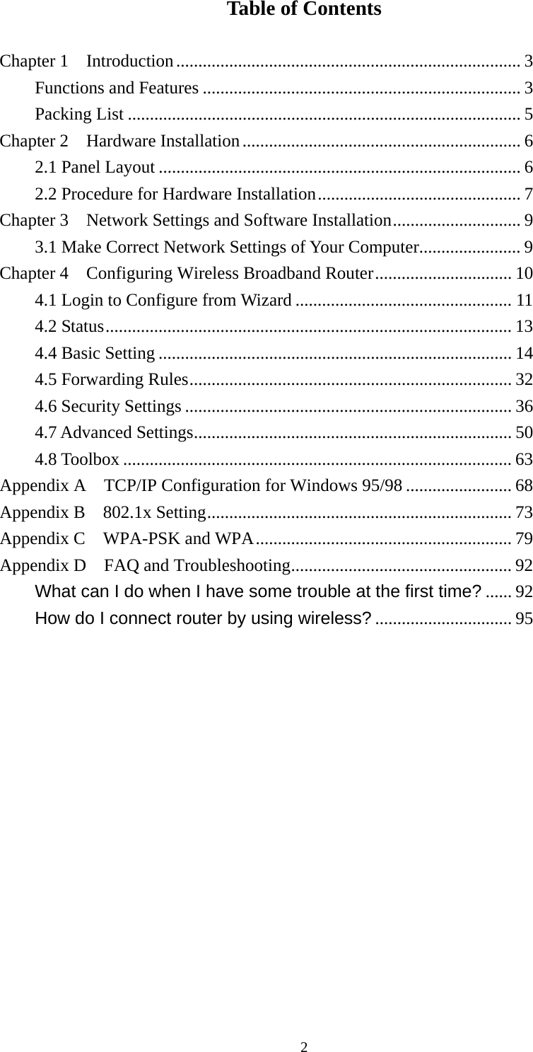
Contents

Users Manual I

    WIQ318AM User’s Manual     Copyright The contents of this publication may not be reproduced in any part or as a whole, stored, transcribed in an information retrieval system, translated into any language, or transmitted in any form or by any means, mechanical, magnetic, electronic, optical, photocopying, manual, or otherwise, without the prior written permission. Trademarks All products, company, brand names are trademarks or registered trademarks of their respective companies. They are used for identification purpose only. Specifications are subject to be changed without prior notice. FCC Interference Statement This equipment has been tested and found to comply with the limits for a Class B digital device pursuant to Part 15 of the FCC Rules. These limits are designed to provide reasonable protection against radio interference in a commercial environment. This equipment can generate, use and radiate radio frequency energy and, if not installed and used in accordance with the instructions in this manual, may cause harmful interference to radio communications. Operation of this equipment in a residential area is likely to cause interference, in which case the user, at his own expense, will be required to take whatever measures are necessary to correct the interference. CE Declaration of Conformity This equipment complies with the requirements relating to electromagnetic compatibility, EN 55022/A1 Class B.   The specification is subject to change without notice. 1
Table of Contents  Chapter 1    Introduction.............................................................................. 3 Functions and Features ........................................................................ 3 Packing List ......................................................................................... 5 Chapter 2    Hardware Installation............................................................... 6 2.1 Panel Layout .................................................................................. 6 2.2 Procedure for Hardware Installation.............................................. 7 Chapter 3    Network Settings and Software Installation............................. 9 3.1 Make Correct Network Settings of Your Computer....................... 9 Chapter 4    Configuring Wireless Broadband Router............................... 10 4.1 Login to Configure from Wizard ................................................. 11 4.2 Status............................................................................................ 13 4.4 Basic Setting ................................................................................ 14 4.5 Forwarding Rules......................................................................... 32 4.6 Security Settings .......................................................................... 36 4.7 Advanced Settings........................................................................ 50 4.8 Toolbox ........................................................................................ 63 Appendix A  TCP/IP Configuration for Windows 95/98 ........................ 68 Appendix B  802.1x Setting..................................................................... 73 Appendix C    WPA-PSK and WPA.......................................................... 79 Appendix D  FAQ and Troubleshooting.................................................. 92 What can I do when I have some trouble at the first time? ...... 92 How do I connect router by using wireless? ............................... 95               2
CCChhhaaapppttteeerrr   111      IIInnntttrrroooddduuuccctttiiiooonnn   Congratulations on your purchase of this outstanding Wireless Broadband Router. This product is specifically designed for Small Office and Home Office needs. It provides a complete SOHO solution for Internet surfing, and is easy to configure and operate even for non-technical users. Instructions for installing and configuring this product can be found in this manual. Before you install and use this product, please read this manual carefully for fully exploiting the functions of this product. Functions and Features      Router Basic functions    z Auto-sensing Ethernet Switch Equipped with a 4-port auto-sensing Ethernet switch. z WAN type supported The router supports some WAN types, Static, Dynamic, PPPoE , PPTP ,L2TP, Dynamic IP with Road Runner. z Firewall All unwanted packets from outside intruders are blocked to protect your Intranet. z DHCP server supported All of the networked computers can retrieve TCP/IP settings automatically from this product. z Web-based configuring Configurable through any networked computer’s web browser using Netscape or Internet Explorer. z Virtual Server supported Enable you to expose WWW, FTP and other services on your LAN to be accessible to Internet users. z User-Definable Application Sensing Tunnel User can define the attributes to support the special applications requiring multiple connections, like Internet gaming, video conferencing, Internet telephony and so on, then this product can sense the application type and open multi-port tunnel for it. z DMZ Host supported Lets a networked computer be fully exposed to the Internet; this function is used when special application sensing tunnel feature is insufficient to allow an application to function correctly. z Statistics of WAN Supported Enables you to monitor inbound and outbound packets     3
Wireless functions  z High speed for wireless LAN connection Up to 54Mbps data rate by incorporating Orthogonal Frequency Division Multiplexing (OFDM). z Roaming Provides seamless roaming within the IEEE 802.11b (11M) and IEEE 802.11g (54M) WLAN infrastructure. z IEEE 802.11b compatible (11M) Allowing inter-operation among multiple vendors. z IEEE 802.11g compatible (54M) Allowing inter-operation among multiple vendors. z Auto fallback 54M, 48M, 36M, 24M, 18M, 12M, 6M data rate with auto fallback in 802.11g mode. 11M, 5.5M, 2M, 1M data rate with auto fallback in 802.11b mode.         Security functions  z Packet filter supported Packet Filter allows you to control access to a network by analyzing the incoming and outgoing packets and letting them pass or halting them based on the IP address of the source and destination. z Domain Filter Supported Let you prevent users under this device from accessing specific URLs. z URL Blocking Supported URL Blocking can block hundreds of websites connection by simply a keyword. z VPN Pass-through The router also supports VPN pass-through. z 802.1X supported When the 802.1X function is enabled, the Wireless user must authenticate to this router first to use the Network service. z Support WPA-PSK and WPA version 1 and 2    When the WPA function is enabled, the Wireless user must authenticate to this router first to   use the Network service z SPI Mode Supported When SPI Mode is enabled, the router will check every incoming packet to detect if this packet is valid. z DoS Attack Detection Supported  4
When this feature is enabled, the router will detect and log the DoS attack comes from the Internet.   Advanced functions  z System time Supported Allow you to synchronize system time with network time server. z E-mail Alert Supported The router can send its info by mail. z Dynamic dns Supported At present,the router has 3 ddns.dyndns,TZO.com and dhs.org. z SNMP Supported The router supports basic SNMP function. z Routing Table Supported Now, the router supports static routing. z Schedule Rule supported Customers can control some functions, like virtual server and packet filters when to access or when to block.    Other functions  z UPNP (Universal Plug and Play)Supported The router also supports this function. The applications: X-box, Msn Messenger.      Packing List  z Wireless broadband router unit z Installation CD-ROM z Power adapter z CAT-5 UTP Fast Ethernet cable           5
CCChhhaaapppttteeerrr   222      HHHaaarrrdddwwwaaarrreee   IIInnnssstttaaallllllaaatttiiiooonnn    2.1 Panel Layout 2.1.1. Front Panel        Figure 2-1 Front Panel  LED: Ports: Port Description PWR  Power inlet WAN  the port where you will connect your cable (or DSL) modem or Ethernet router. Port 1-4  the ports where you will connect networked computers and other devices.  6
2.1.2. Rear Panel  Figure 2-2 Rear Panel LED:  LED Function Color Status Description Power  Power indication  Green  On  Power is being applied to this product. Status  System status   Green Blinking  Status is flashed once per second to indicate system is alive.  WAN  WAN port activity   Green  On  The WAN port is linked. Blinking  The WAN port is sending or receiving data.  WLAN  Wireless activity  Green  Blinking  Sending or receiving data via wireless Link. 1~4  Link status Green  On  An active station is connected to the corresponding LAN port. Blinking  The corresponding LAN port is sending or receiving data. Speed 10/100  Data Rate Green  On  Data is transmitting in 100Mbps on the corresponding LAN port. Reset        To reset system settings to factory defaults 2.2 Procedure for Hardware Installation  2.    Decide where to place your Wireless Broadband Router  7
You can place your Wireless Broadband Router on a desk or other flat surface, or you can mount it on a wall. For optimal performance, place your Wireless Broadband Router in the center of your office (or your home) in a location that is away from any potential source of interference, such as a metal wall or microwave oven. This location must be close to power and network connection. 2. Setup LAN connection a. Wired LAN connection: connects an Ethernet cable from your computer’s Ethernet port to one of the LAN ports of this product. b. Wireless LAN connection: locate this product at a proper position to gain the best transmit performance.  Figure 2-3 Setup of LAN and WAN connections for this product.  3.  Setup WAN connection Prepare an Ethernet cable for connecting this product to your cable/xDSL modem or Ethernet backbone. Figure 2-3 illustrates the WAN connection. 4.  Power on  Connecting the power cord to power inlet and turning the power switch on, this product will automatically enter the self-test phase. When it is in the self-test phase, the indicators M1 will be lighted ON for about 10 seconds, and then M1 will be flashed 3 times to indicate that the self-test operation has finished. Finally, the M1 will be continuously flashed once per second to indicate that this product is in normal operation.     8
CCChhhaaapppttteeerrr   333      NNNeeetttwwwooorrrkkk   SSSeeettttttiiinnngggsss   aaannnddd   SSSoooffftttwwwaaarrreee   IIInnnssstttaaallllllaaatttiiiooonnn    To use this product correctly, you have to properly configure the network settings of your computers and install the attached setup program into your MS Windows platform (Windows 95/98/NT/2000).  3.1 Make Correct Network Settings of Your Computer  The default IP address of this product is 192.168.123.254, and the default subnet mask is 255.255.255.0. These addresses can be changed on your need, but the default values are used in this manual. If the TCP/IP environment of your computer has not yet been configured, you can refer to Appendix A to configure it. For example, 1. configure IP as 192.168.123.1, subnet mask as 255.255.255.0 and gateway as 192.168.123.254, or more easier, 2. configure your computers to load TCP/IP setting automatically, that is, via DHCP server of this product. After installing the TCP/IP communication protocol, you can use the ping command to check if your computer has successfully connected to this product. The following example shows the ping procedure for Windows 95 platforms. First, execute the ping command ping 192.168.123.254 If the following messages appear:   Pinging 192.168.123.254 with 32 bytes of data: Reply from 192.168.123.254: bytes=32 time=2ms TTL=64 a communication link between your computer and this product has been successfully established. Otherwise, if you get the following messages, Pinging 192.168.123.254 with 32 bytes of data: Request timed out. There must be something wrong in your installation procedure. You have to check the following items in sequence: 1. Is the Ethernet cable correctly connected between this product and your computer? Tip: The LAN LED of this product and the link LED of network card on your computer must be lighted. 2. Is the TCP/IP environment of your computers properly configured? Tip: If the IP address of this product is 192.168.123.254, the IP address of your computer must be 192.168.123.X and default gateway must be 192.168.123.254.  9
CCChhhaaapppttteeerrr   444      CCCooonnnfffiiiggguuurrriiinnnggg   WWWiiirrreeellleeessssss   BBBrrroooaaadddbbbaaannnddd   RRRooouuuttteeerrr    This product provides Web based configuration scheme, that is, configuring by your Web browser, such as Netscape Communicator or Internet Explorer. This approach can be adopted in any MS Windows, Macintosh or UNIX based platforms.                  10
4.1 Login to Configure from Wizard  Activate your browser, and disable the proxy or add the IP address of this product into the exceptions. Then, type this product’s IP address in the Location (for Netscape) or Address (for IE) field and press ENTER. For example: http://192.168.123.254. After the connection is established, you will see the web user interface of this product. There are two appearances of web user interface: for general users and for system administrator. To log in as an administrator, enter the system password (the factory setting is  ”admin”) in the System Password field and click on the Log in button. If the password is correct, the web appearance will be changed into administrator configure mode. As listed in its main menu, there are several options for system administration.  The user can setup step by step to finish the connection with Wizard.  Setup Wizard will guide you through a basic configuration procedure step by step.Press    ”Next >”  11
  If the user finishes those steps and the router shows as below. It means that customers can enjoy Internet.    12
4.2 Status   This option provides the function for observing this product’s working status: A. WAN Port Status.   If the WAN port is assigned a dynamic IP, there may appear a “Renew” or “Release” button on the Sidenote column. You can click this button to renew or release IP manually.  B. Statistics of WAN: enables you to monitor inbound and outbound packets           13
 4.4 Basic Setting Please Select “Advanced Setup” to Setup                 14
4.4.1 Primary Setup – WAN Type, Virtual Computers   Press “Change”  15
 This option is primary to enable this product to work properly. The setting items and the web appearance depend on the WAN type. Choose correct WAN type before you start. 1. LAN IP Address: the local IP address of this device. The computers on your network must use the LAN IP address of your product as their Default Gateway. You can change it if necessary. 2. WAN Type: WAN connection type of your ISP. You can click Change button to choose a correct one from the following four options: A. Static IP Address: ISP assigns you a static IP address. B. Dynamic IP Address: Obtain an IP address from ISP automatically. C. Dynamic IP Address with Road Runner Session Management.(e.g. Telstra BigPond) D. PPP over Ethernet: Some ISPs require the use of    PPPoE to connect to their services. E. PPTP: Some ISPs require the use of    PPTP to connect to their services. F.    L2TP: Some ISPs require the use of    L2TP to connect to their services  4.4.1.1 Static IP Address WAN IP Address, Subnet Mask, Gateway, Primary and Secondary DNS: enter the proper setting provided by your ISP. 4.4.1.2 Dynamic IP Address  16
1. Host Name: optional. Required by some ISPs, for example, @Home. 2. Renew IP Forever: this feature enables this product to renew your IP address automatically when the lease time is expiring-- even when the system is idle.  4.4.1.3 Dynamic IP Address with Road Runner Session Management.(e.g. Telstra BigPond) 1. LAN IP Address is the IP address of this product. It must be the default gateway of your   computers.  2.        WAN Type is Dynamic IP Address. If the WAN type is not correct, change it!   3.        Host Name: optional. Required by some ISPs, e.g. @Home.   4.        Renew IP Forever: this feature enable this product renew IP address automatically when the lease time is being expired even the system is in idle state.   4.4.1.4 PPP over Ethernet 1.   PPPoE Account and Password: the account and password your ISP assigned to you. For security,         this field appears blank. If you don't want to change the password, leave it empty. 2.   PPPoE Service Name: optional. Input the service name if your ISP requires it. Otherwise, leave   it blank. 3.   Maximum Idle Time: the amount of time of inactivity before disconnecting your PPPoE session.   Set it to zero or enable Auto-reconnect to disable this feature. 4.  Maximum Transmission Unit (MTU): Most ISP offers MTU value to users. The most common MTU value is 1492.   5. Connection Control:There are 3 modes to select: Connect-on-demand:The device will link up with ISP when the clients send outgoing packets. Auto-Reconnect(Always-on):The device will link upw with ISP until the connection is established. Manually:The device will not make the link until someone clicks the connect-button in the Staus-page.    4.4.1.5 PPTP First,Please check your ISP assigned and Select Static IP Address or Dynamic IP Address.   17
1.      My IP Address and My Subnet Mask: the private IP address and subnet mask your ISP assigned   to you.   2.    Server IP Address: the IP address of the PPTP server.   3.      PPTP Account and Password: the account and password your ISP assigned to you. If you don't want to change the password, keep it empty.   3.      Connection ID: optional. Input the connection ID if your ISP requires it.   4.      Maximum Idle Time: the time of no activity to disconnect your PPTP session. Set it to zero or   enable Auto-reconnect to disable this feature. If Auto-reconnect is enabled, this product will   connect to ISP automatically, after system is restarted or connection is dropped. 5. Connection Control:There are 3 modes to select: Connect-on-demand:The device will link up with ISP when the clients send outgoing packets. Auto-Reconnect(Always-on):The device will link upw with ISP until the connection is established. Manually:The device will not make the link until someone clicks the connect-button in the Staus-page.     18
  4.4.1.6 L2TP First,Please check your ISP assigned and Select Static IP Address or Dynamic IP Address. For example:Use Static 1.      My IP Address and My Subnet Mask: the private IP address and subnet mask your ISP assigned   to you.   2.    Server IP Address: the IP address of the PPTP server.   3.      PPTP Account and Password: the account and password your ISP assigned to you. If you don't want to change the password, keep it empty.   3.      Connection ID: optional. Input the connection ID if your ISP requires it.   4.      Maximum Idle Time: the time of no activity to disconnect your PPTP session. Set it to zero or   enable Auto-reconnect to disable this feature. If Auto-reconnect is enabled, this product will    19
connect to ISP automatically, after system is restarted or connection is dropped. 6. Connection Control:There are 3 modes to select: Connect-on-demand:The device will link up with ISP when the clients send outgoing packets. Auto-Reconnect(Always-on):The device will link upw with ISP until the connection is established. Manually:The device will not make the link until someone clicks the connect-button in the Staus-page.            20
4.4.1.7 Virtual Computers(Only for Static and dynamic IP address Wan type)  Virtual Computer enables you to use the original NAT feature, and allows you to setup the one-to-one mapping of multiple global IP address and local IP address.   • Global IP: Enter the global IP address assigned by your ISP.   • Local IP: Enter the local IP address of your LAN PC corresponding to the global IP address.   • Enable: Check this item to enable the Virtual Computer feature.          21
4.4.2 DHCP Server   Press “More>>” The settings of a TCP/IP environment include host IP, Subnet Mask, Gateway, and DNS configurations. It is not easy to manually configure all the computers and devices in your network. Fortunately, DHCP Server provides a rather simple approach to handle all these settings. This product supports the function of DHCP server. If you enable this product’s DHCP server and configure your computers as “automatic IP allocation” mode, then when your computer is powered on, it will automatically load the proper TCP/IP settings from this product. The settings of DHCP server include the following items: 1. DHCP Server: Choose “Disable” or “Enable.” 2. IP pool starting Address/ IP pool starting Address: Whenever there is a request, the DHCP server will automatically allocate an unused IP address from the IP address pool to the requesting computer. You must specify the starting and ending address of the IP address pool. 3. Domain Name: Optional, this information will be passed to the client. 4. Primary DNS/Secondary DNS: This feature allows you to assign DNS Servers 5. Primary WINS/Secondary WINS: This feature allows you to assign WINS Servers 6. Gateway: The Gateway Address would be the IP address of an alternate Gateway.   This function enables you to assign another gateway to your PC, when DHCP server offers an IP to your PC.   22
4.4.3 Wireless Setting, 802.1X setting and WDS    Wireless settings allow you to set the wireless configuration items. Wireless : The user can enable or disalbe wireless function.  Network ID (SSID): Network ID is used for identifying the Wireless LAN (WLAN). Client stations can roam freely over this product and other Access Points that have the same Network ID. (The factory setting is “default”)  SSID Broadcast: The router will Broadcast beacons that have some information, including ssid so that   The wireless clients can know how many ap devices by scanning function in the network. Therefore, This function is disabled, the wireless clients can not find the device from beacons.  Channel: The radio channel number. The permissible channels depend on the Regulatory Domain.   The factory setting is as follow: channel 6 for North America; channel 7 for European (ETSI); channel 7 for Japan.  Security: Select the data privacy algorithm you want. Enabling the security can protect your data while  23
it is transferred from one station to another.  There are several security types to use:  WEP :  When you enable the 128 or 64 bit WEP key security, please select one WEP key to be used and input 26 or 10 hexadecimal (0, 1, 2…8, 9, A, B…F) digits.  802.1X Check Box was used to switch the function of the 802.1X. When the 802.1X function is enabled, the Wireless user must authenticate to this router first to use the Network service.   RADIUS Server  IP address or the 802.1X server’s domain-name.   RADIUS Shared Key  Key value shared by the RADIUS server and this router. This key value is consistent with the key value in the RADIUS server.  24
WPA-PSK 1. Select Encryption and Pre-share Key Mode If you select HEX, you have to fill in 64 hexadecimal (0, 1, 2…8, 9, A, B…F) digits If ASCII, the length of pre-share key is from 8 to 63. 2. Fill in the key, Ex 12345678   WPA Check Box was used to switch the function of the WPA. When the WPA function is enabled, the Wireless user must authenticate to this router first to use the Network service. RADIUS Server  IP address or the 802.1X server’s domain-name.   Select Encryption and RADIUS Shared Key If you select HEX, you have to fill in 64 hexadecimal (0, 1, 2…8, 9, A, B…F) digits If ASCII, the length of pre-share key is from 8 to 63. Key value shared by the RADIUS server and this router. This key value is consistent with the key value in the RADIUS server.  25

Navigation menu