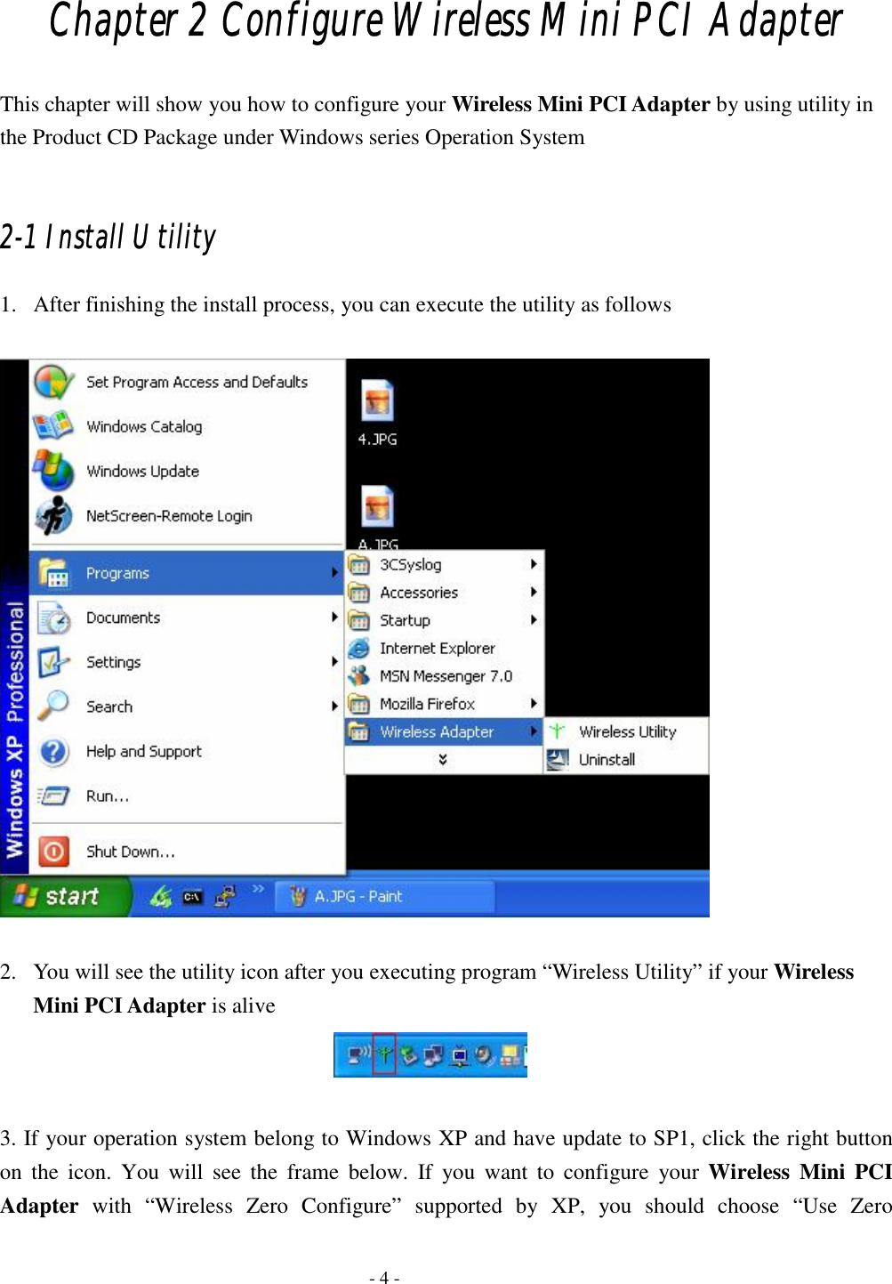
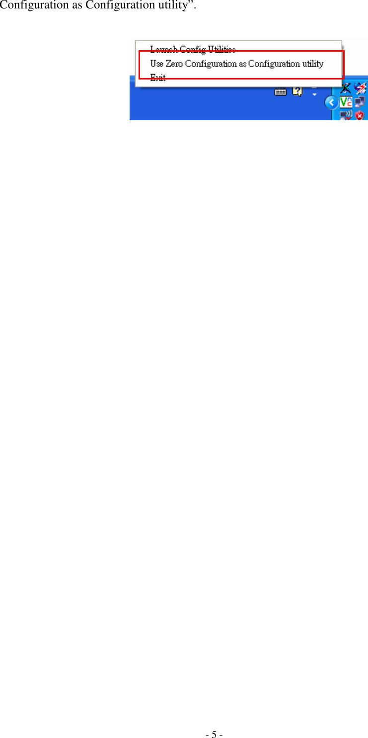
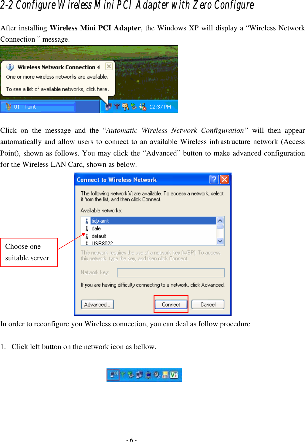
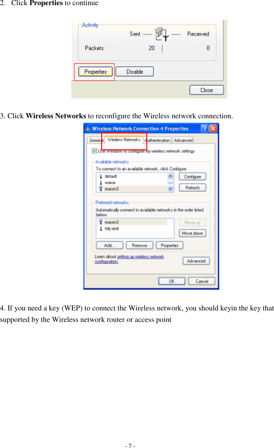
Advance Multimedia Internet Technology WL533M Mini PCI Adapter User Manual
Advance Multimedia Internet Technology Inc. Mini PCI Adapter Users Manual
UserManual.wiki
>
Advance Multimedia Internet Technology
>
WL533M User Manual
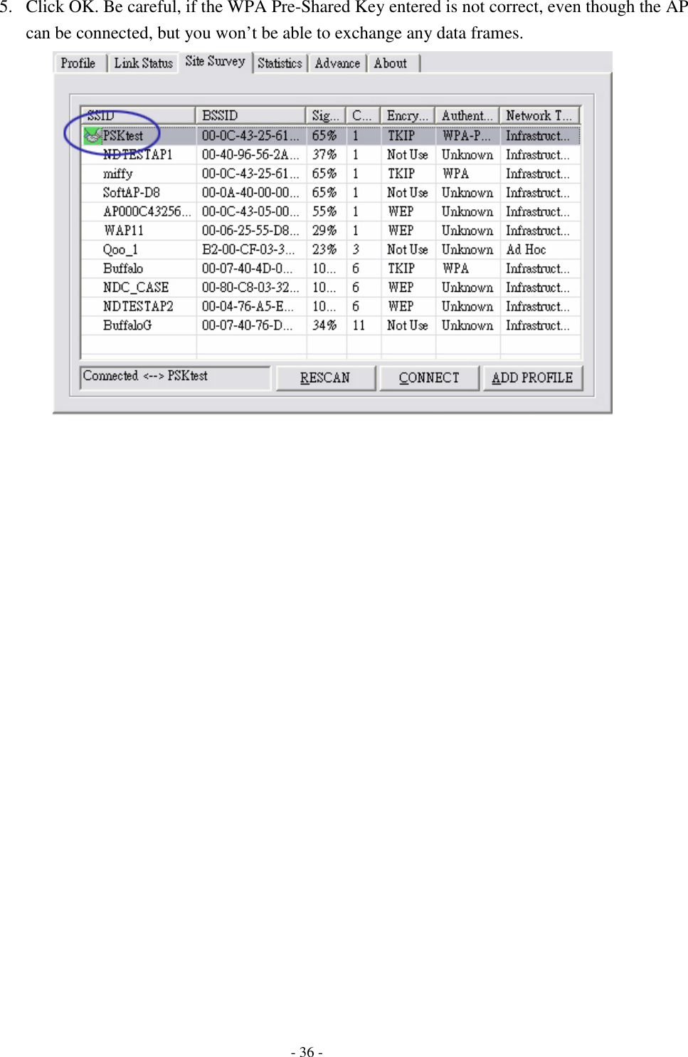
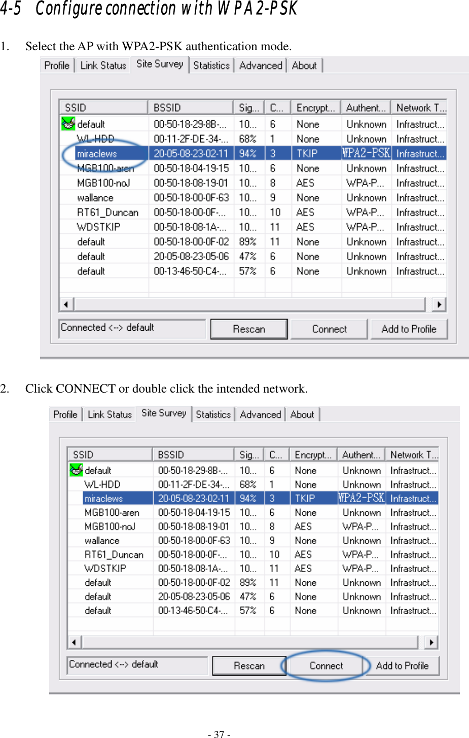
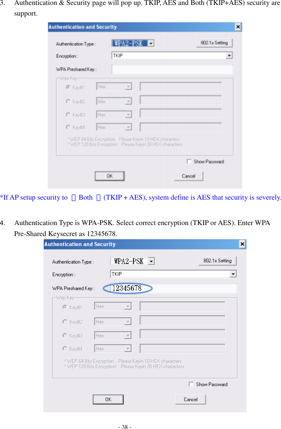
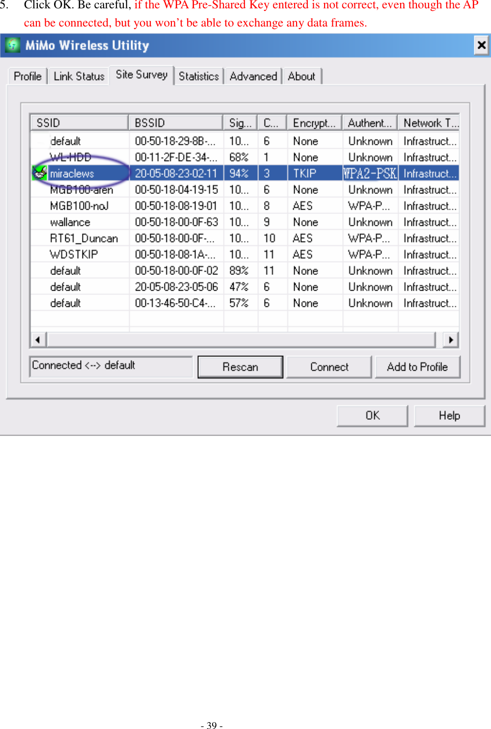
Users Manual
Navigation menu
Upload a User Manual
Namespaces
Wiki Guide
HTML
PDF
Info
Views
User Manual
Discussion / Help
Navigation