Advance Multimedia Internet Technology WL533M Mini PCI Adapter User Manual
Advance Multimedia Internet Technology Inc. Mini PCI Adapter Users Manual
Users Manual
11B/G
Wireless Mini PCI Adapter
WL533MAM
User’s Manual

FCC Information
This device complies with Part 15 of the FCC Rules. Operation is subject to the following two
conditions:
1. This device may not cause harmful interference.
2. This device must accept any interference received; including interference that may cause
undesired operation.
Federal Communications Commission (FCC) Statement.
This Equipment has been tested and found to comply with the limits for a Class B digital device,
pursuant to Part 15 of the FCC rules. These limits are designed to provide reasonable protection
against harmful interference in a residential installation. This equipment generates uses and can
radiate radio frequency energy and if not installed and used in accordance with the instructions,
may cause harmful interference to radio communications. However, there is no guarantee that
interference will not occur in a particular installation. If this equipment does cause harmful
interference to radio or television reception, which can be determined by turning the equipment off
and on, the user is encouraged to try to correct the interference by one or more of the following
measures:
- Reorient or relocate the receiving antenna.
- Increase the separation between the equipment and receiver.
- Connect the equipment into an outlet on a circuit different from that to which the receiver is
connected.
- Consult the dealer or an experienced radio/TV technician for help.
FCC RF Radiation Exposure Statement:
1. This Transmitter must not be co-located or operating in conjunction with any other antenna or
transmitter.
2. This equipment complies with FCC RF radiation exposure limits set forth for an uncontrolled
environment. This equipment should be installed and operated with a minimum distance of 20
centimeters between the radiator and your body.
IMPORTANT NOTE: In the event that these conditions can not be met (for example certain laptop
configurations or co-location with another transmitter), then the FCC authorization is no longer
considered valid and the FCC ID can not be used on the final product. In these circumstances, the
OEM integrator will be responsible for re-evaluating the end product (including the transmitter) and
obtaining a separate FCC authorization.
End Product Labeling
This transmitter module is authorized only for use in devices where the antenna may be installed
such that 20 cm may be maintained between the antenna and users (for example access points,
routers, wireless ADSL modems, and similar equipment). The final end product must be labeled in
visible area with the following:
“Contains TX FCC ID: PBLWL533M”
End Product Manual Information
The user manual for end users must include the following information in a prominent location
“IMPORTANT NOTE: To comply with FCC RF exposure compliance requirements, the antenna
used for this transmitter must be installed to provide a separation distance of at least 20cm from all
persons and must not be co-located or operating in conjunction with any other antenna or
transmitter.”
Other important note:
1. The end user may not be provided with instructions to remove or install the device.
2. Changes or modifications not expressly approved by the party responsible for compliance
could void the user's authority to operate the equipment.
3. This device is authorised for OEM integration only.
-1-
- 2 -
Chapter 1 Install Driver for Windows Series
This section describes the installation of the 11b/g Wireless Mini PCI Adapter driver for the
Windows98/ME/2000 and Windows XP operating systems.
1-1 Set up 11b/g Wireless Mini PCI Adapter for Windows Series
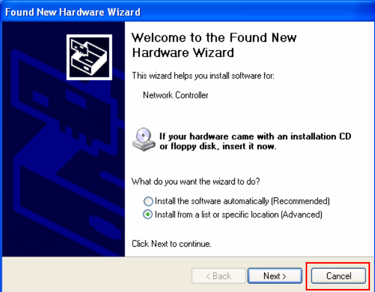
Step 1: After inserting the Wireless Mini PCI Adapter into the Mini PCI port on notebook or
desktop, the Windows will auto-detect the Wireless Mini PCI Adapter and a “Found New
Hardware Wizard” window will show up. Select “Cancel” to install the driver from CD-Rom.
- 3 -
Step 2: Insert the Product CD-ROM into the CD-ROM drive. Select “Setup.exe” to install Driver
and Utility.
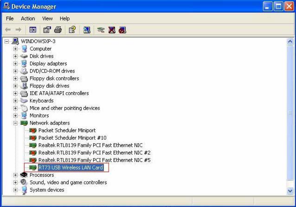
Step 3: After installing the driver, you can check if your device is active in the device management
- 4 -
Chapter 2 Configure Wireless Mini PCI Adapter
This chapter will show you how to configure your Wireless Mini PCI Adapter by using utility in
the Product CD Package under Windows series Operation System
2-1 Install Utility
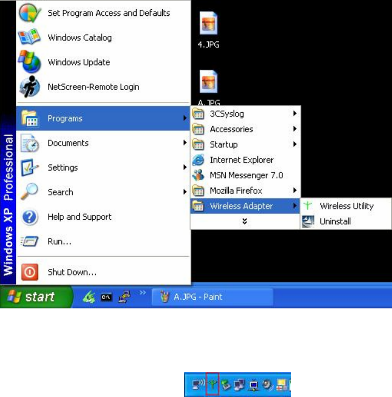
1. After finishing the install process, you can execute the utility as follows
2. You will see the utility icon after you executing program “Wireless Utility” if your Wireless
Mini PCI Adapter is alive
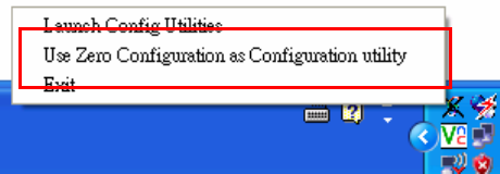
3. If your operation system belong to Windows XP and have update to SP1, click the right button
on the icon. You will see the frame below. If you want to configure your Wireless Mini PCI
Adapter with “Wireless Zero Configure” supported by XP, you should choose “Use Zero
- 5 -
Configuration as Configuration utility”.
- 6 -
2-2 Configure Wireless Mini PCI Adapter with Zero Configure
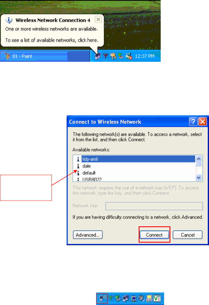
After installing Wireless Mini PCI Adapter, the Windows XP will display a “Wireless Network
Connection ” message.
Click on the message and the “Automatic Wireless Network Configuration” will then appear
automatically and allow users to connect to an available Wireless infrastructure network (Access
Point), shown as follows. You may click the “Advanced” button to make advanced configuration
for the Wireless LAN Card, shown as below.
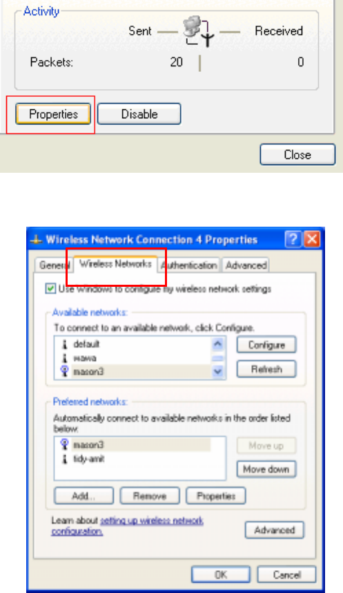
In order to reconfigure you Wireless connection, you can deal as follow procedure
1. Click left button on the network icon as bellow.
Choose one
suitable server
- 7 -
2. Click Properties to continue
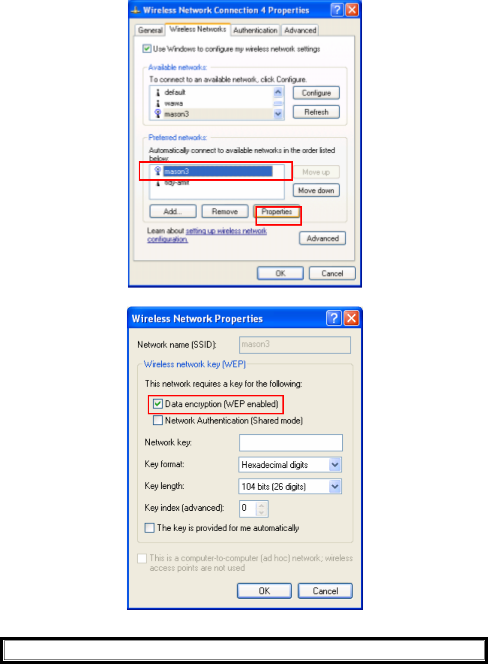
3. Click Wireless Networks to reconfigure the Wireless network connection.
4. If you need a key (WEP) to connect the Wireless network, you should keyin the key that
supported by the Wireless network router or access point
- 8 -
- 9 -
Chapter 3 Configure Wireless Mini PCI Adapter with
“ Wireless Utility” for Windows 98/ME/2000/XP
Click the utility icon, and you will see the application interface as step 2.
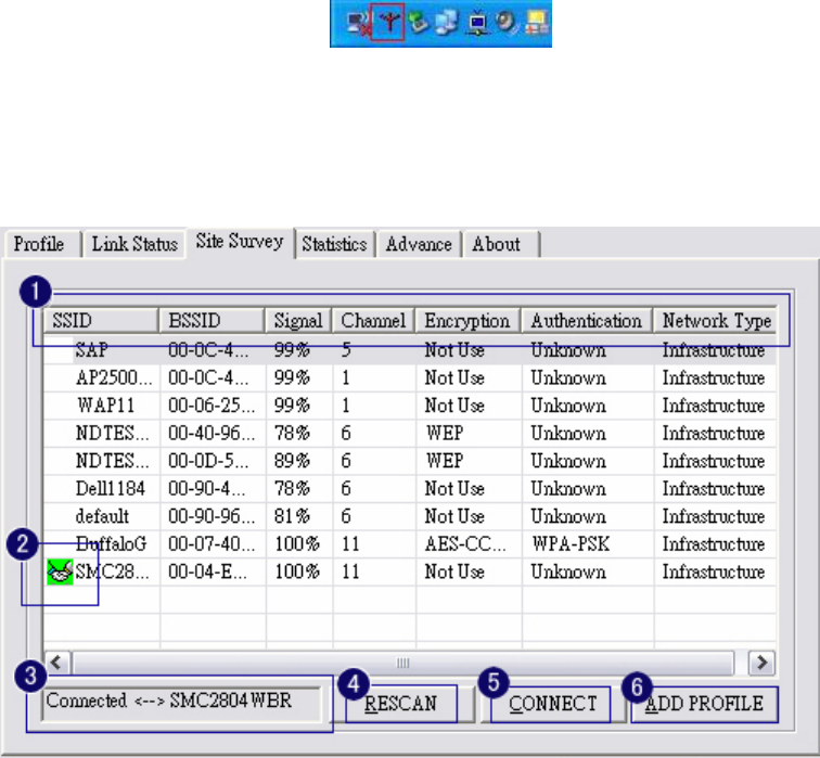
3-1 Site Survey Page
1. The means of item
z SSID : Name of AP
z BSSID : Mac Address of AP
z Signal : Signal strength of AP
z Channel : AP used channel
z Encryption : what encrypted mechanism does AP used, the encrypted mechanism contain four
ways , WEP, AES, TKIP, NOT USE
z Authentication : What authentication mechanism does AP used.

- 10 -
z Network Type : What Network Type does the AP belong to.
2. The connected AP
z the system will choose the suitable AP when you start up RaConfig in the first time
z if you want to connect with another AP, double click mouse’s left button in the SSID of AP.
z indicate connect successful.
3. if the connect is success, it will show the SSID of the connected AP
4. rescan and upgrade all the AP’s information in time
5. connect with selected AP
6. Save the selected AP’s information to Profile
3-1-1 Add/Edit Profile
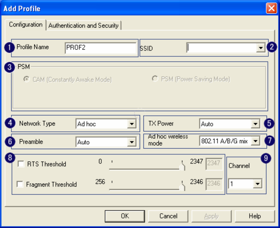
System Configuration: as figure bellow
- 11 -
1. Profile Name: Different AP can be set up into different Profile Name
2. SSID: The drop-down menu can select which AP is detected by system
3. Power Save Mode: can select〔CAM(Constantly Awake Mode)〕 or 〔Power Saving Mode〕
mode. Selecting the” CAM when AC Power” means the power saving mode can automatically
switch into CAM, if the computer uses the AC power, not using the batteries instead. Selecting
the “Power Save Mode” can only work under the infrastructure mode.
4. Network Type: Can select “Infrastructure” or “802.11 Ad Hoc” mode. When set up to
“Infrastructure” mode, the “Power Saving” mode will be enabled, but the “11b Preamble Type”
will not; When set up to “802.11 Ad Hoc” mode, the “Power Saving Mode” will not be enabled,
but “11b Preamble” will, and the channel selection in the session 7 will show up as well.
5. TX Power: Transmit power, the amount of power used by a radio transceiver to send the signal
out. User can choose power value by sliding the bar.
6. Preamble: There are three types, Auto, Long and Short are supported.
7. Ad hoc wireless mode: There are five types. 802.11B only, 802.11 B/G mixed 802.11A only,
802.11 A/B/G mixed and 802.11G only modes are supported.

- 12 -
8. RTS Threshold: User can adjust the RTS threshold number by sliding the bar or key in the value
directly. The default value is 2312.
9. Fragment Threshold: User can adjust the RTS threshold number by sliding the bar or key in the
value directly. The default value is 2312.
Note: Channel: Only available for setting under ad-hoc mode. User can choose the channel
frequency to start their ad-hoc network.
Profile function is based on the needs to set up the most linkable AP in order to record the system
configuration and to set up the authentication security. The function of each session is shown below
- 13 -
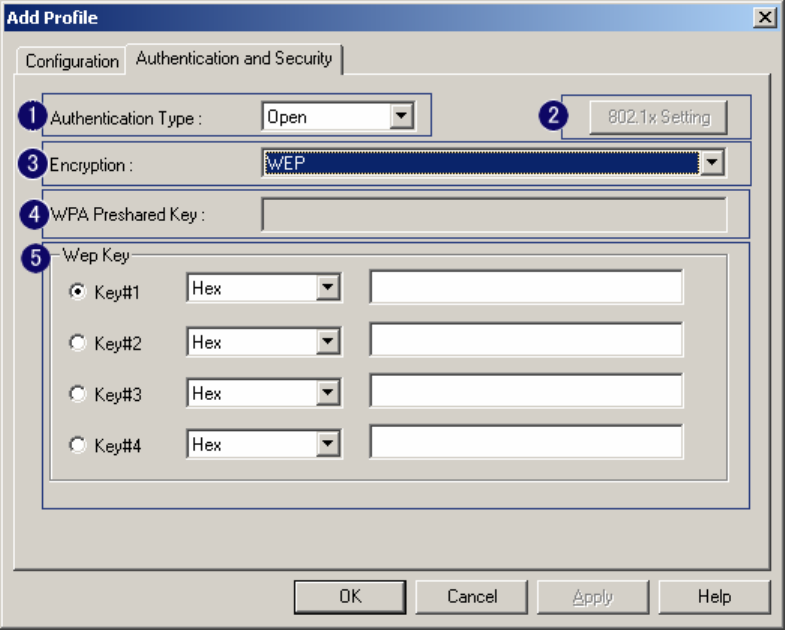
3-2 Authentication & Security
As shown in picture. When the Encryption feature is enabled, the other setups are same as the said
WEP setting.
1. Authentication Type: There are three type of authentication modes supported by RaConfig.
They are open, Shared, WPA-PSK and WPA system.
2. 802.1x Setting: It will display to set when user use radius server to authenticate client certificate
for WPA authentication mode. The detail operation will explain in section 5-6 Configure
connection with WPA by 802.1x setting
3. Encryption Type: For open and shared authentication mode, the selection of encryption type are
None and WEP. For WPA, WPA2, WPA-PSK and WPA2-PSK authentication mode, the
encryption type supports both TKIP and AES.
4. WPA Pre-shared Key: This is the shared secret between AP and STA. For WPA-PSK and
WPA2-PSK authentication mode, this field must be filled with character longer than 8 and less
than 32 lengths.
5. WEP Key: Only valid when using WEP encryption algorithm. The key must matched AP key.
There are several formats to enter the keys.
i. Hexadecimal、40bits:10 Hex characters.
- 14 -
ii. Hexadecimal、128bits:32Hex characters.
iii. ASCII、40bits:5 ASCII characters.
iv. ASCII、128bits:13 ASCII characters.
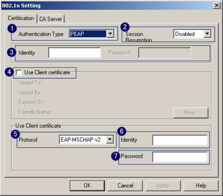
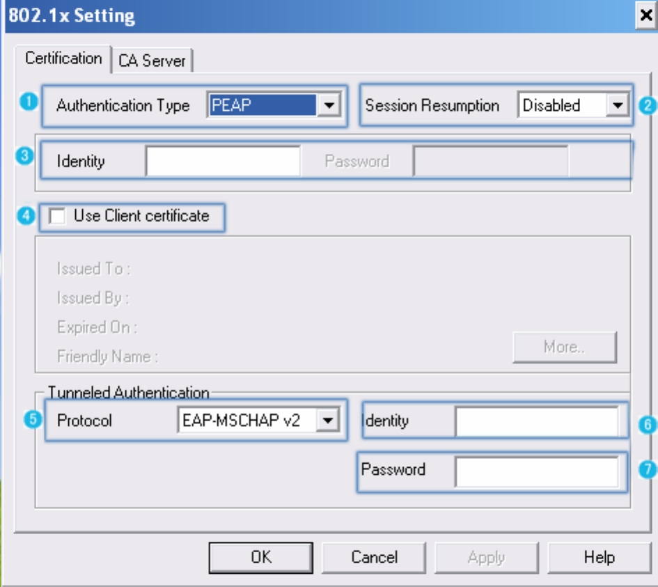
3-2-1 802.1x Setting
802.1x is a authentication for 『WPA』and 『WPA2』certificate to server. Show as figure
1. Authentication type:
i. PEAP: Protect Extensible Authentication Protocol. PEAP transport securely
authentication data by using tunneling between PEAP clients and an authentication
server. PEAP can authenticate wireless LAN clients using only server-side
certificates, thus simplifying the implementation and administration of a secure
wireless LAN.
ii. TLSSmart Card: Transport Layer Security. Provides for certificate-based and
mutual authentication of the client and the network. It relies on client-side and
server-side certificates to perform authentication and can be used to dynamically
generate user-based and session-based WEP keys to secure subsequent
communications between the WLAN client and the access point.
- 15 -
iii. TTLS: Tunneled Transport Layer Security. This security method provides for
certificate-based, mutual authentication of the client and network through an
encrypted channel. Unlike EAP-TLS, EAP-TTLS requires only server-side
certificates.
iv. LEAP: Light Extensible Authentication Protocol. It is an EAP authentication type
used primarily in Cisco Aironet WLANs. It encrypts data transmissions using
dynamically generated WEP keys, and supports mutual authentication.
v. MD5-Challenge: Message Digest Challenge. Challenge is an EAP authentication
type that provides base-level EAP support. It provides for only one-way
authentication - there is no mutual authentication of wireless client and the network.
2. Session Resumption: user can choose “ Disable ”, “ Reauthentication ”, “ Roaming ”,
“ SameSsid ” and “ Always ”.
3. Identity and Password: Identity and password for server.
4. Use Client Certificate: Client Certificate for server authentication.
5. Tunnel Authentication
i. Protocol: Tunnel protocol, List information include “ EAP-MSCHAP ”,
“ EAP-MSCHAP v2 ”, “ CAHAP ” and “ MD5 ”
ii. Tunnel Identity: Identity for tunnel.
iii. Tunnel Password: Password for tunnel.
6. CA Server: Certificate Authority Server. Each certificate is signed or issued by it. The detail
operation will explain in section 4-2-2 CA Server
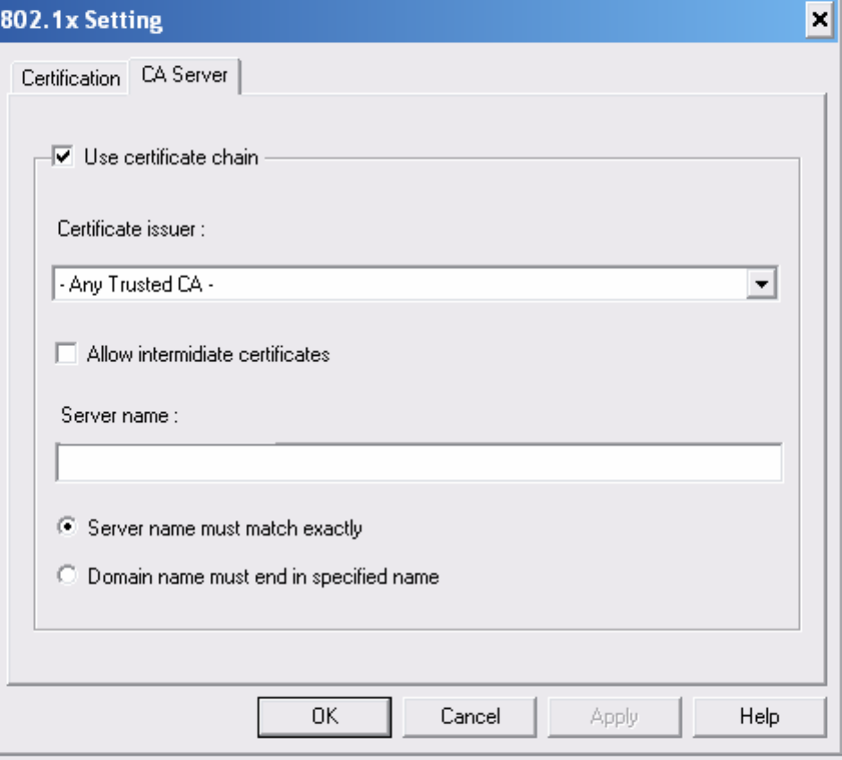
3-2-2 CA Server
Depending on the EAP in use, only the server or both the server and client may be authenticated and
require a certificate. Server certificates identify a server, usually an authentication or RADIUS
server to clients. Most EAPs require a certificate issued by a root authority or a trusted commercial
CA. Show as the figure.
1. Certificate issuer: Choose use server that issuer of certificates.
2. Allow intimidate certificates: It must be in the server certificate chain between the server
certificate and the server specified in the certificate issuer must be field.
3. Server name: Enter an authentication sever root.
- 16 -
- 17 -
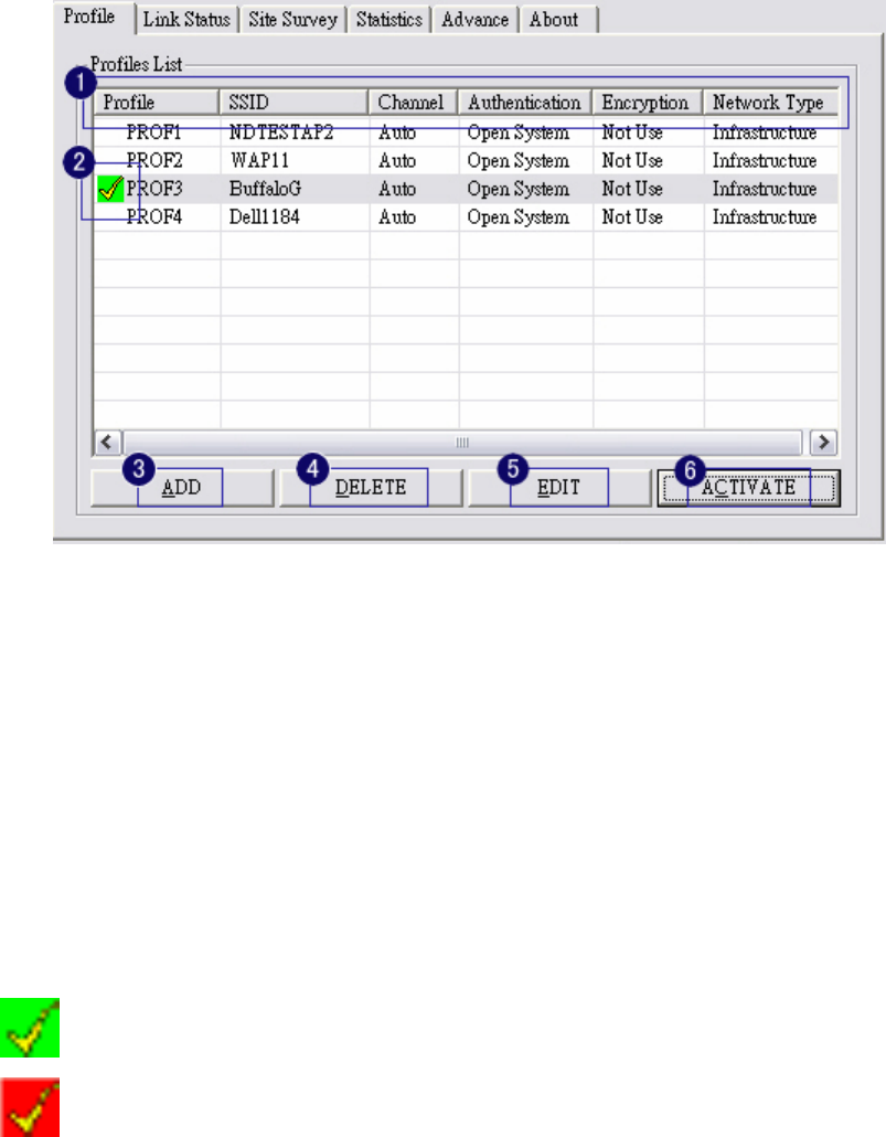
3-3 Profile Page
Profile can book keeping your favorite wireless setting among your home, office, and other public
hotspot. You may save multiple profiles, and activate the correct one at your preference.
1. Definition of each field:
i. Profile: Name of profile, preset to PROF* (* indicate 1, 2, 3,).
ii. SSID: AP or Ad-hoc name.
iii. Cannel: Channel in use for Ad-Hoc mode.
iv. Authentication: Authentication mode.
v. Encryption: Security algorithm in use.
vi. Network Type: Network’s type, icluding infrastructure and Ad-Hoc.
2. Connection status
Indicate connection is successful on currently activated profile.
Indicate connection is failed on currently activated profile.
3. Add a new profile.
4. Delete an existing profile.
5. Edit Profile
6. Activate selected profile.
- 18 -
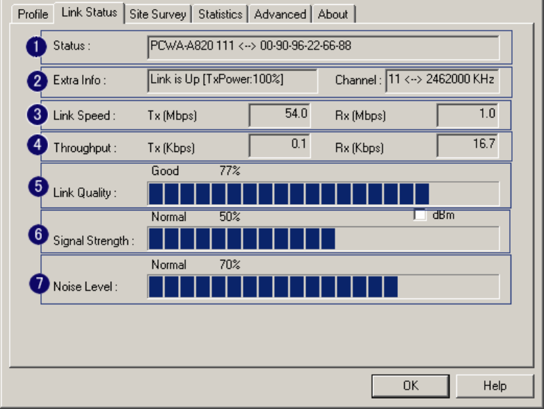
3-4 Link Status Page
Show the information of linking status. As show in picture 20, the description of each session is said
as following:
1. Status: Current connection status. If no connection, if will show Disconnected. Otherwise, the
SSID and BSSID will show here.
2. Extra Info: Display link status and current channel in use.
3. Link Speed: Show current transmit rate and receive rate.
4. Throughout: Display transmits and receive throughput in unit of K bits/sec.
5. Link Quality: Display connection quality based on signal strength and TX/RX packet error rate.
6. Signal Strength: Receive signal strength, user can choose to display as percentage or dBm
format
7. Noise Level: Display noise signal strength.
- 19 -
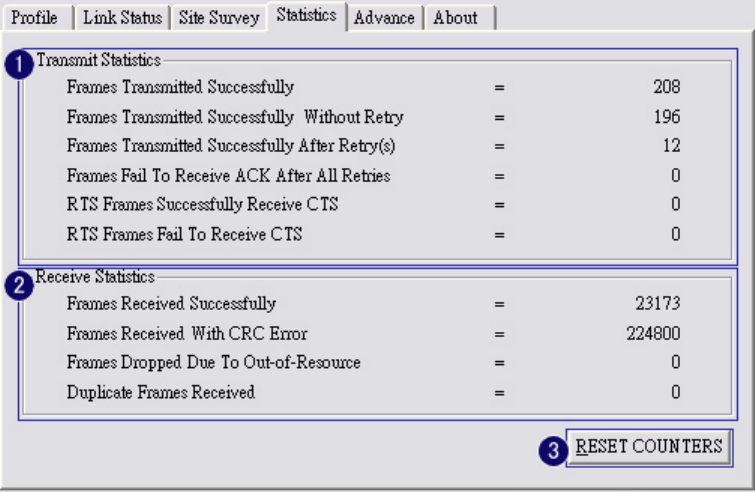
3-5 Statistics Page
Statistics page displays the detail counter information based on 802.11 MIB counters. This page
translates that MIB counters into a format easier for user to understand.
1. Transmit Statistics:
i. Frames Transmitted Successfully: Frames successfully sent.
ii. Frames Transmitted Successfully Without Retry: Frames successfully sent without
any retry.
iii. Frames Transmitted Successfully After Retry: Frames successfully sent with one or
more reties.
iv. Frames Fail To Receive ACK After All Retries: Frames failed transmit after hitting
retry limit.
v. RTS Frames Successfully Receive CTS: Successfully receive CTS after sending RTS
frame.
vi. RTS Frames Fail To Receive CTS: Failed to receive CTS after sending RTS.
2. Receive Statistics:
i. Frames Received Successfully: Frames received successfully.
ii. Frames Received With CRC Error: Frames received with CRC error.
iii. Frames Dropped Due To Out-of-Resource: Frames dropped due to resource issue.
iv. Duplicate Frames Received: Duplicate received frames.

- 20 -
3. To zero the statistic numbers of transmitting and receiving data.
- 21 -
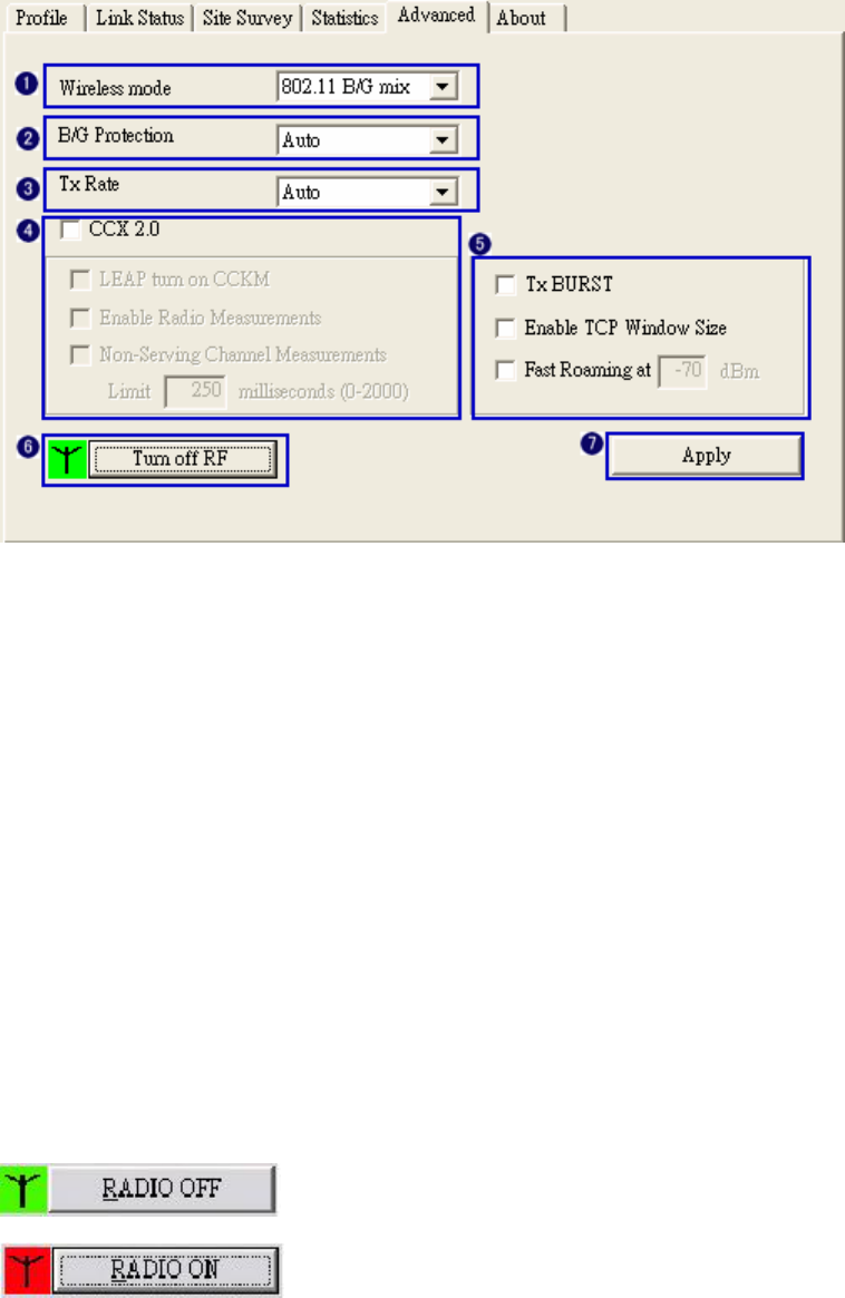
3-6 Advance Page
The advance setting is shown as follows. The description of each session is said as following:
1. Wireless mode: Select wireless mode. 802.11B only, 802.11 B/G mixed 802.11A only, 802.11
A/B/G mixed and 802.11G only modes are supported.
2. 11B/G Protection: ERP protection mode of 802.11G definition. User can chosse from Auto, On,
and Off
i. Auto: STA will dynamically change as AP announcement.
ii. On: Always send frame with protection.
iii. Off: Always send frame without protection.
3. TX Rate: Manually force the Transmit using selected rate. Default is auto.
4. CCX2.0: support Cisco Compatible Extensions function:
i. LEAP turn on CCKM
ii. Enable Radio Measurement: can channel measurement every 0~2000 milliseconds.
5. Tx Burst: Ralink’s proprietary frame burst mode.
6. Wireless radio signal control
z : means to open the wireless radio signal and show simultaneously:
z : means to close the wireless radio signal and show simultaneously:

- 22 -
7. Apply Means the modification of session 1~4 are formally used.
- 23 -
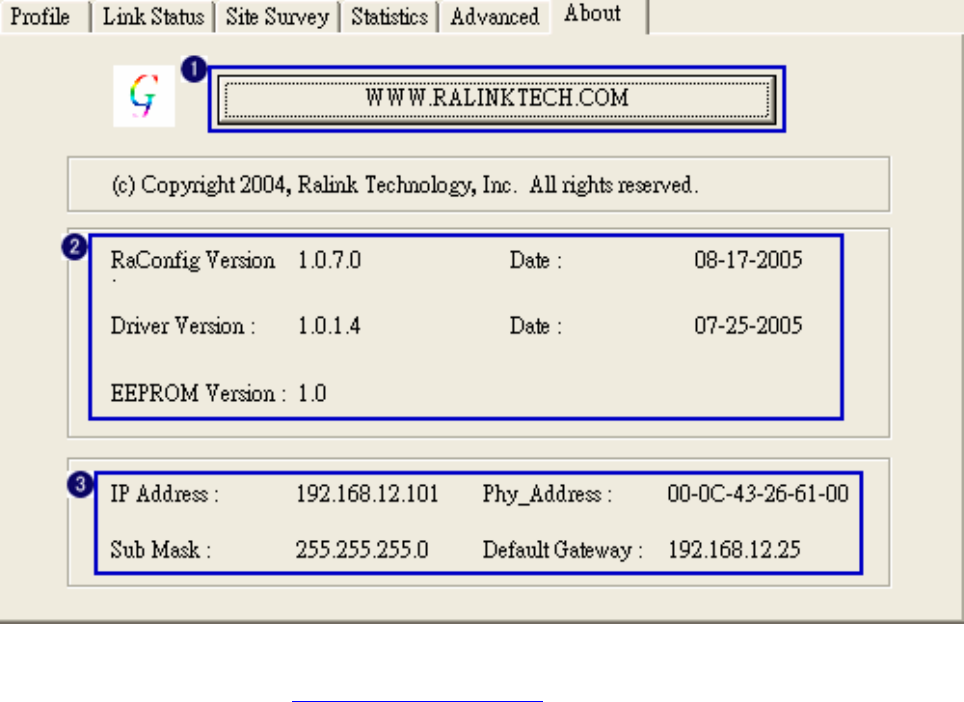
3-7 About Page
About page display the wireless card and driver version information shown as follow figure .
1. Connect to RaLink’s website: Ralink Technology, Corp.
2. Display Configuration Utility, Driver, and EEPROM version information.
3. Display Wireless NIC MAC address.
- 24 -
Chapter 4 Example
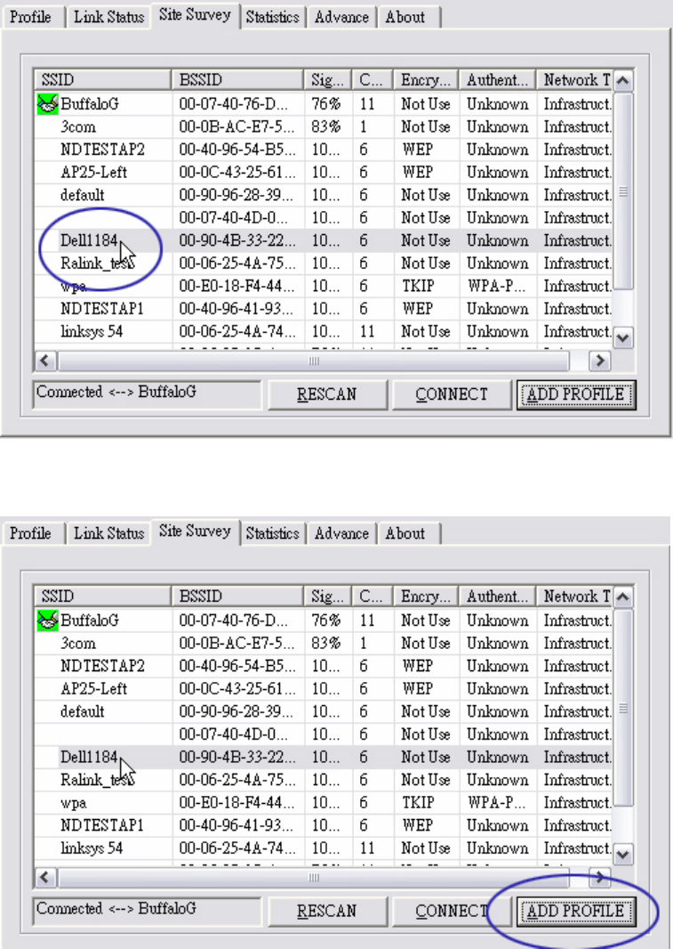
4-1 Adding profile in site survey page
1. Select the indented network from site survey list.
2. Click ADD PROFILE.
- 25 -
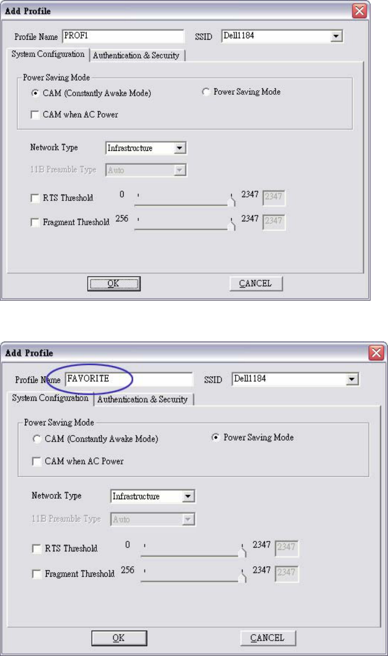
3. System will pop up Add Profile windows
4. Change profile Name from PROF1 to FAVORITE.
- 26 -
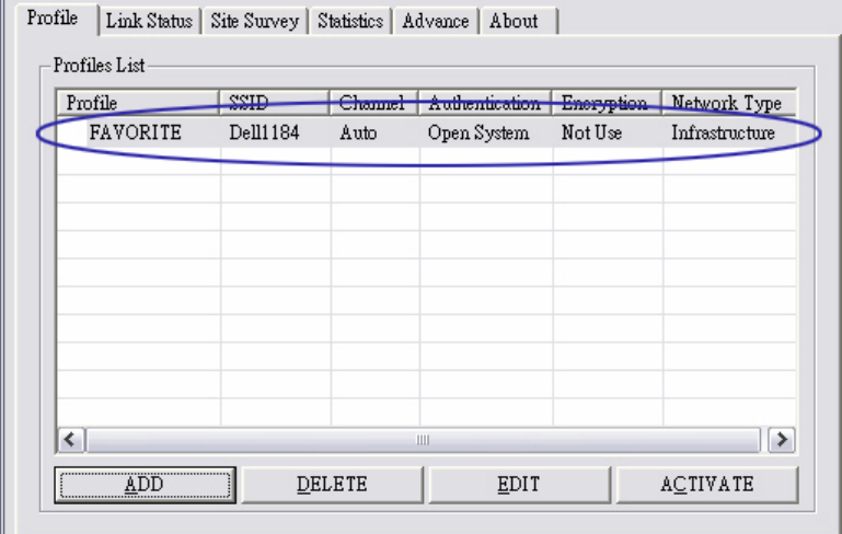
5. Click OK without changing other value.
- 27 -
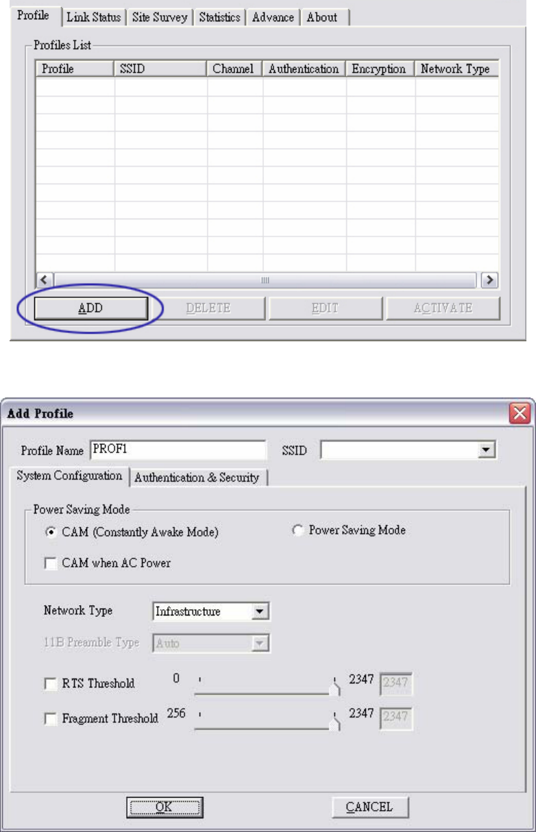
4-2 Add profile in profile page
1. Click ADD in profile page
2. Add Profile page will pop up
- 28 -
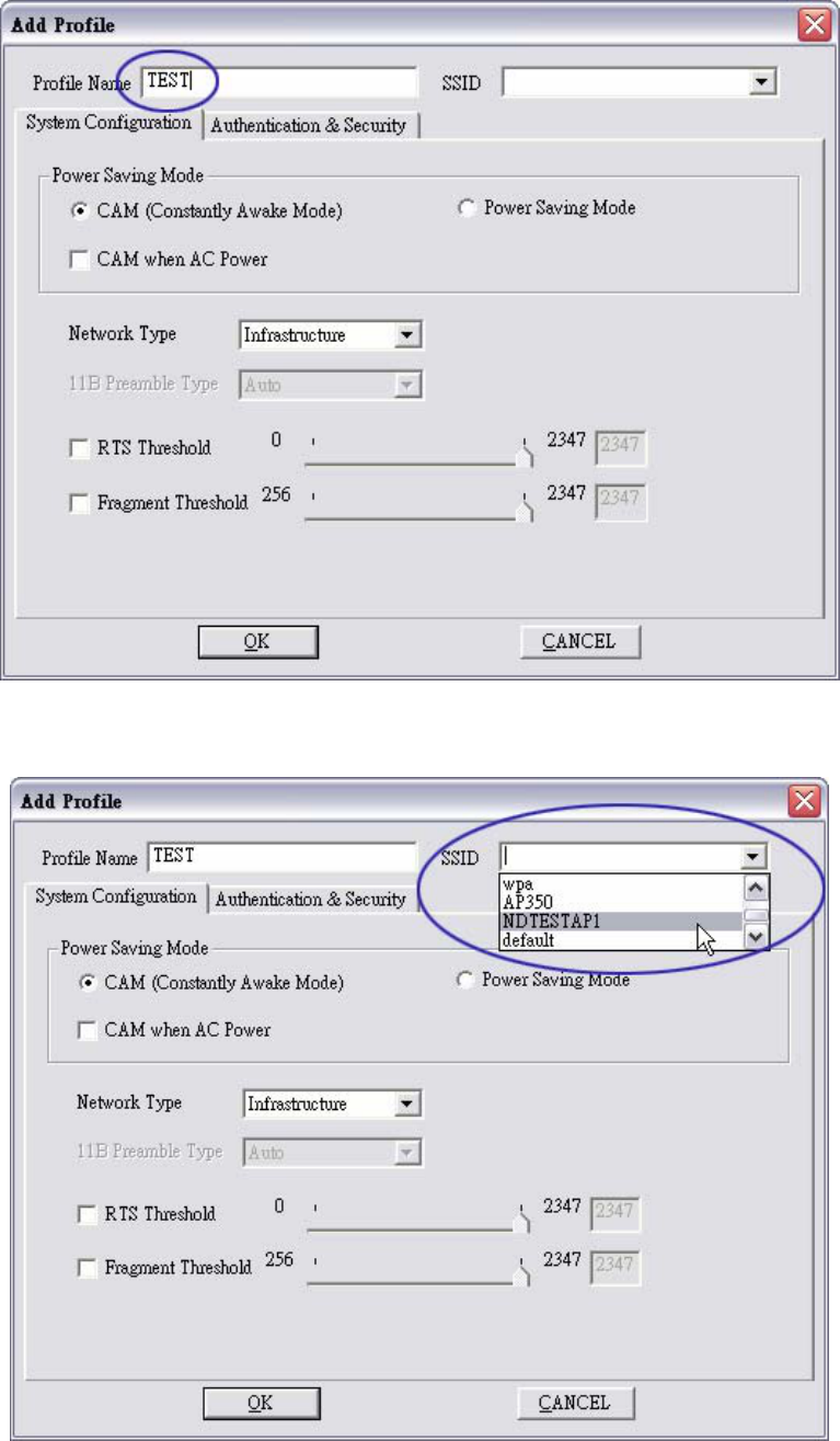
3. Change profile name to TEST.
4. Pull down SSID and select one intended AP. The AP list is the result of last site survey.
- 29 -
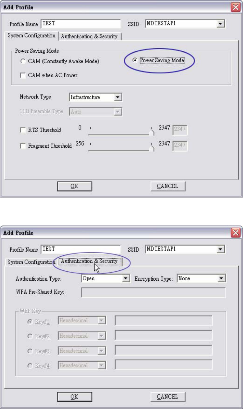
5. Set Power Saving Mode.
6. Click Authentication & Security page
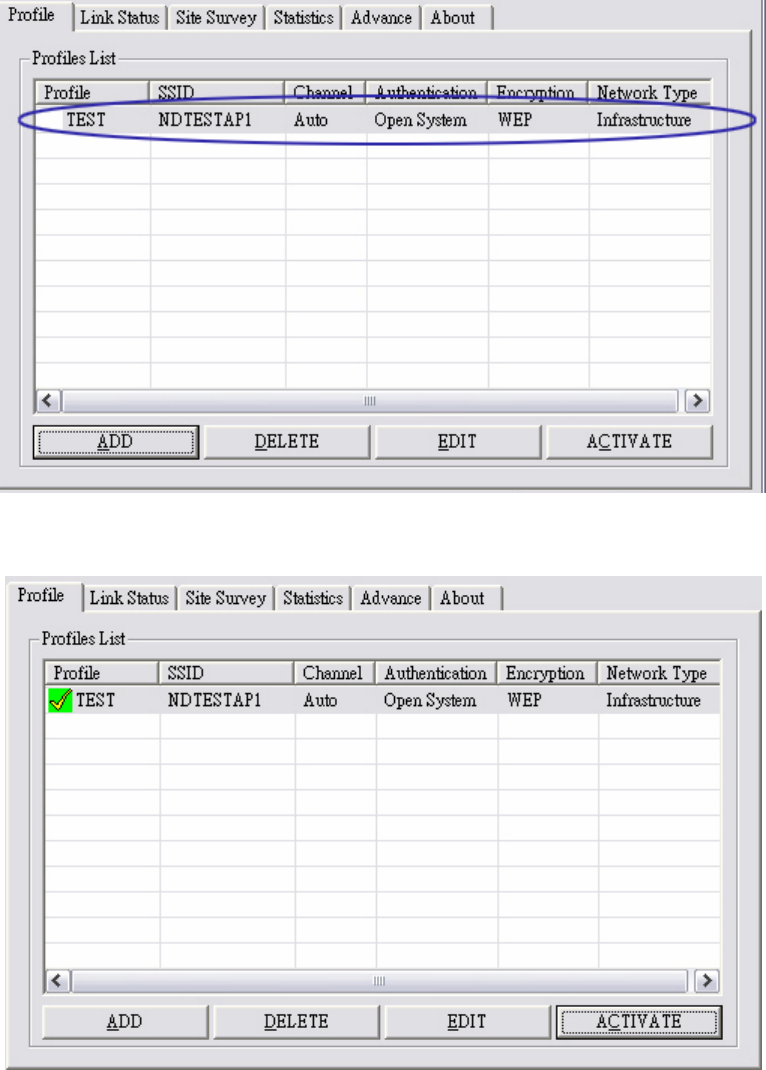
- 30 -
7. Click OK. Then we can find the profile name appears in the grid.
8. Click ACTIVATE. Activate the profile setting.
- 31 -
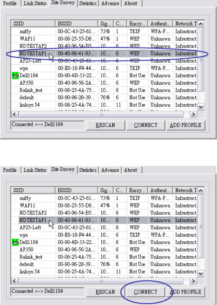
4-3 WEP encryption
1. Select AP with WEP encryption.
2. Click CONNECT or doucle click intended network.
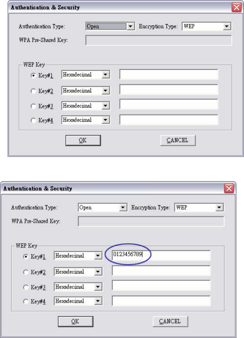
- 32 -
3. Authentication & Security page pop up.
4. Enter 0123456789 at Key#1 which is same as our intended AP’s setting.
- 33 -
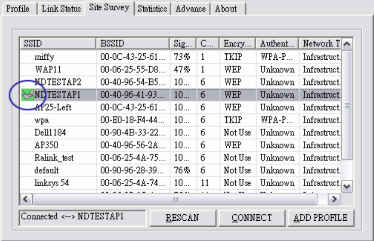
5. Click OK. The result will look like the below figure.
- 34 -
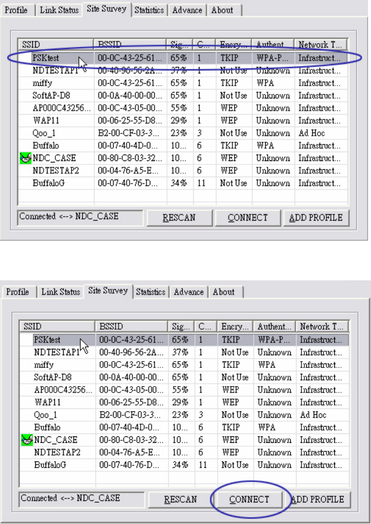
4-4 Configure connection with WPA-PSK
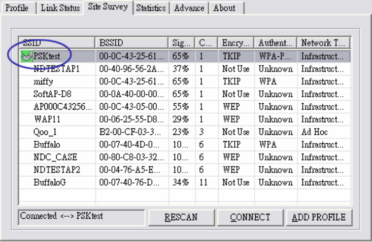
1. Select the AP with WPA-PSK authentication mode.
2. Click CONNECT or double click the intended network.
- 35 -
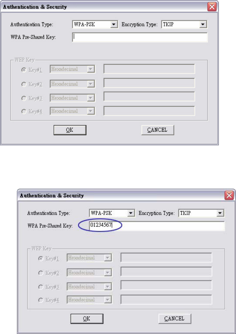
3. Authentication & Security page will pop up.
*If AP setup security to 〝Both 〞(TKIP + AES), system define is AES that security is severely.
4. Authentication Type is WPA-PSK. Select correct encryption (TKIP or AES).Enter WPA
Pre-Shared Keysecret as 01234567.
- 36 -
5. Click OK. Be careful, if the WPA Pre-Shared Key entered is not correct, even though the AP
can be connected, but you won’t be able to exchange any data frames.
- 37 -
4-5 Configure connection with WPA2-PSK
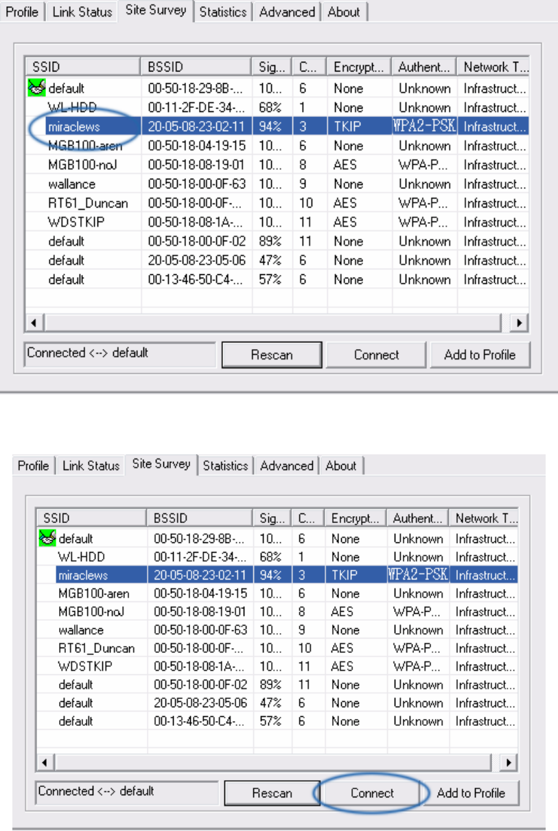
1. Select the AP with WPA2-PSK authentication mode.
2. Click CONNECT or double click the intended network.
- 38 -
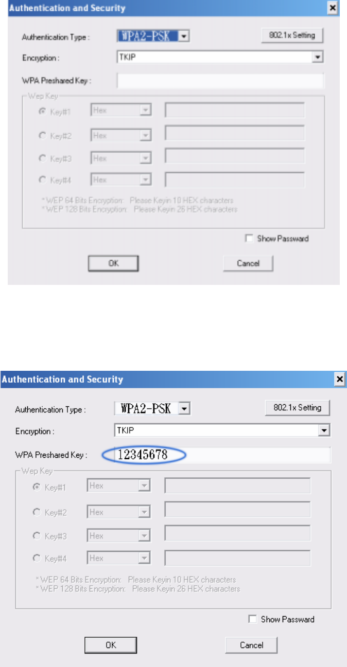
3. Authentication & Security page will pop up. TKIP, AES and Both (TKIP+AES) security are
support.
*If AP setup security to 〝Both 〞(TKIP + AES), system define is AES that security is severely.
4. Authentication Type is WPA-PSK. Select correct encryption (TKIP or AES). Enter WPA
Pre-Shared Keysecret as 12345678.
- 39 -
5. Click OK. Be careful, if the WPA Pre-Shared Key entered is not correct, even though the AP
can be connected, but you won’t be able to exchange any data frames.
- 40 -
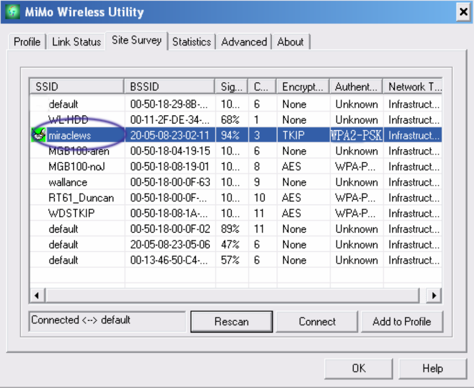
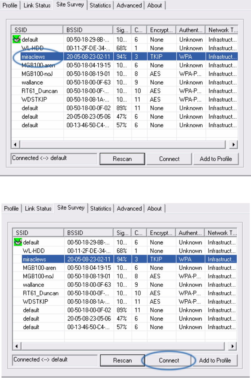
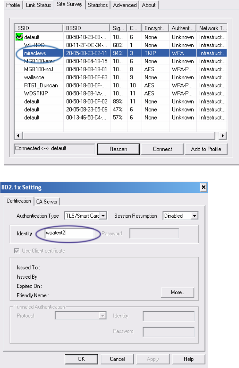
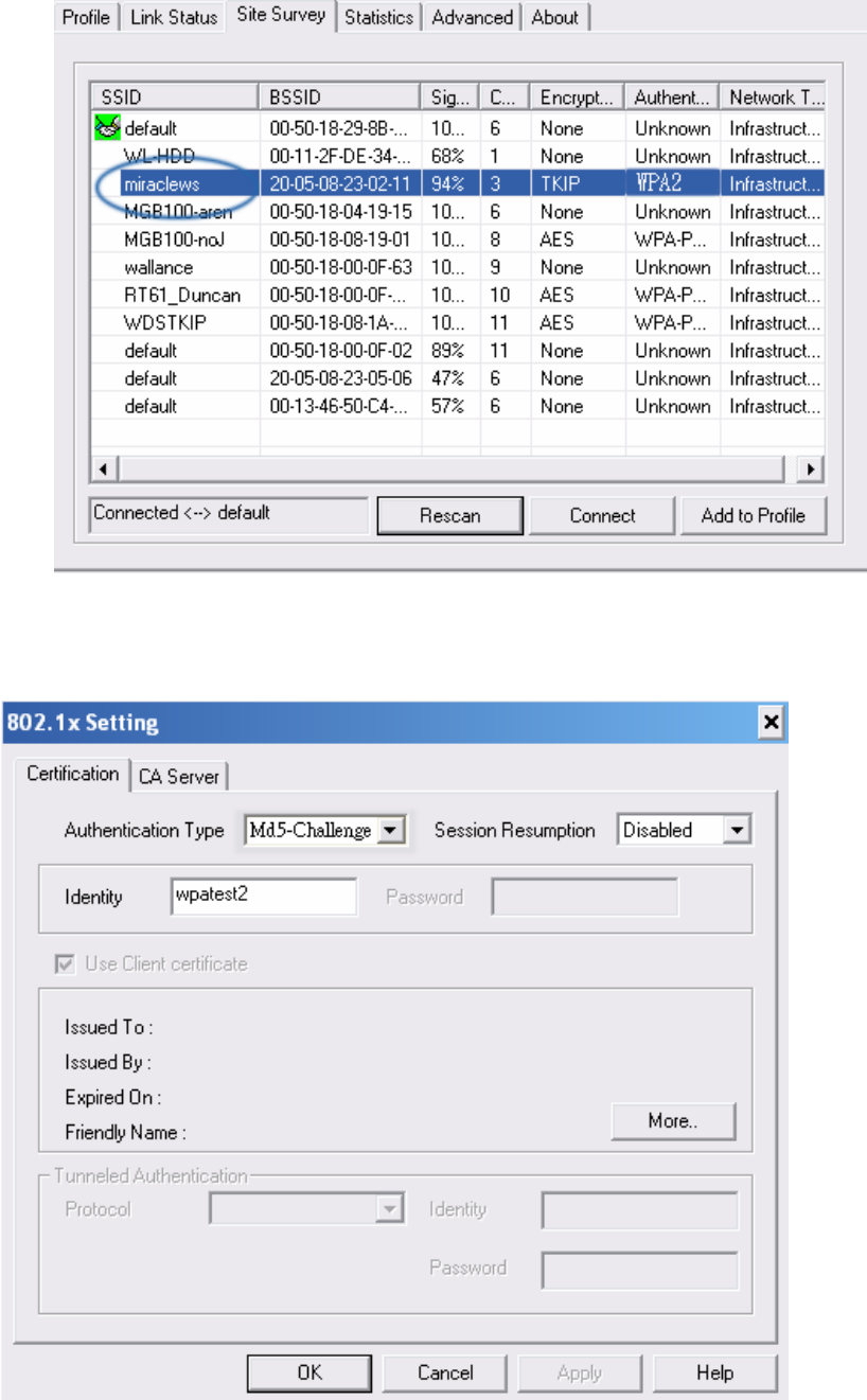
4-6 Configure connection with WPA by 802.1x setting
1. Select A.P with WPA authentication mode.
2. Click CONNECT or double click the intended network
- 41 -
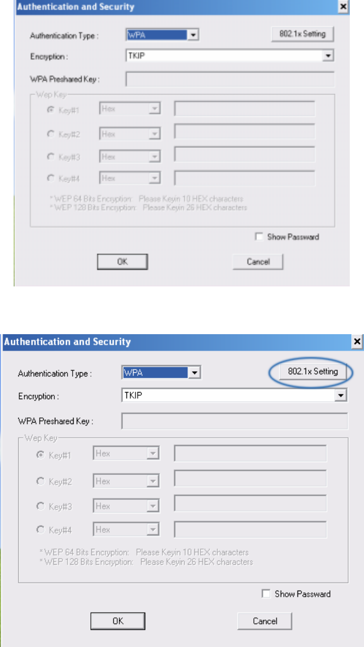
3. Authentication & Security page will pop up. TKIP, AES and Both (TKIP+AES) security are
support.
*If AP setup security to 〝Both 〞(TKIP + AES), system define is AES that security is severely.
4. Click 802.1x setting.

- 42 -
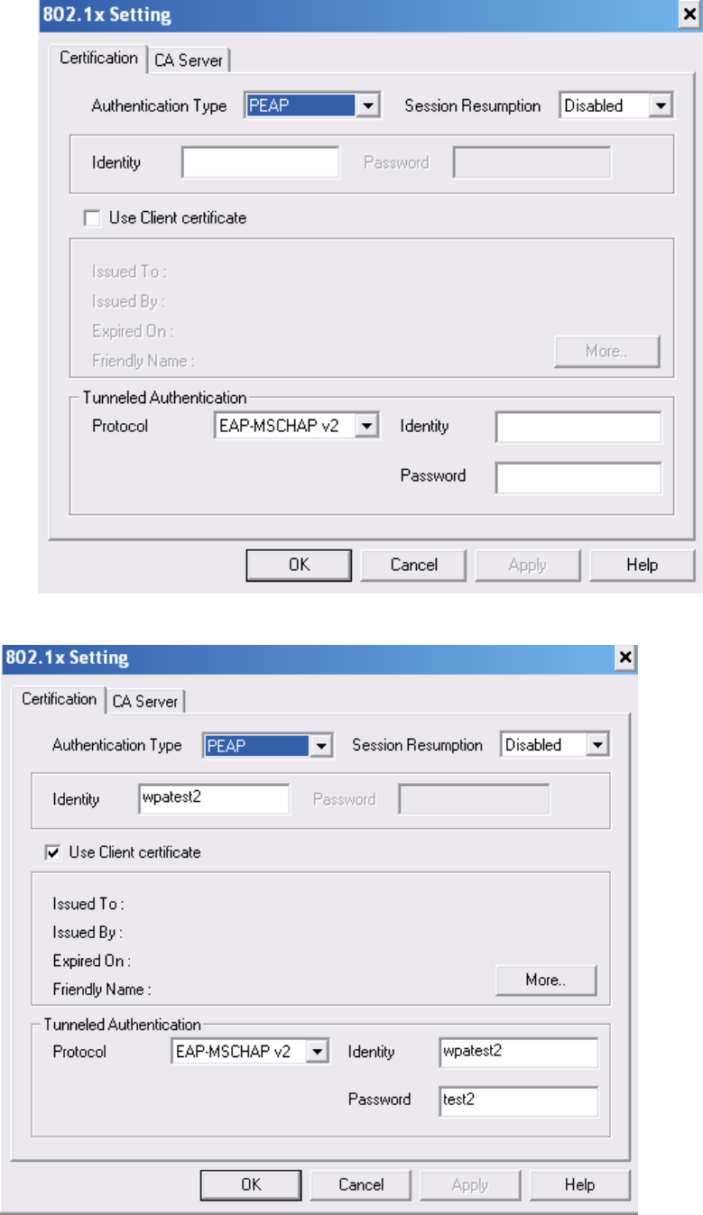
5. 802.1x setting page will pop up.
6. Authentication type and setting method:
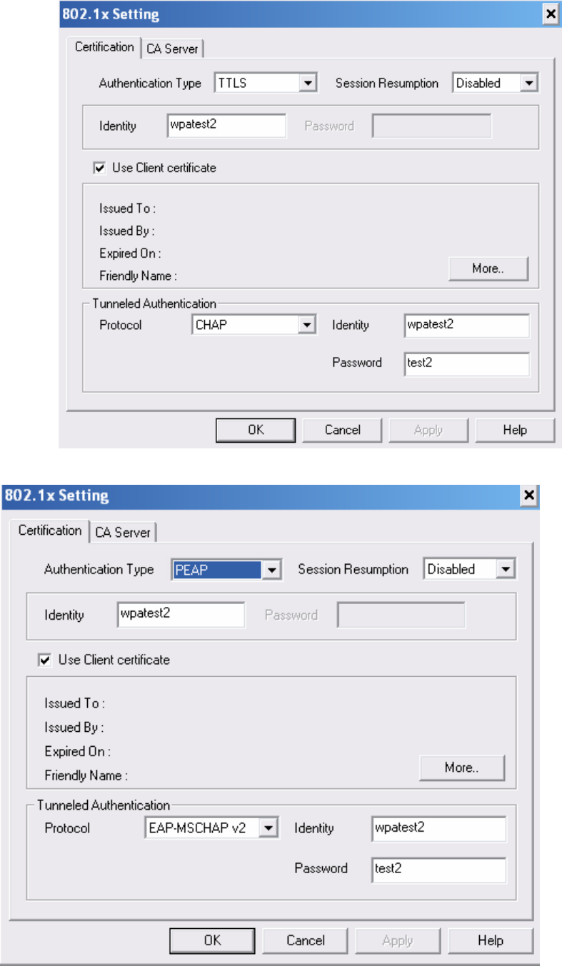
1. PEAP:
i. Authentication type chooses PEAP, key identity into wpatest2. Protocol chooses
EAP-MSCHAP v2 for tunnel authentication, tunnel identity is wpatest2 and tunnel
password is test2. Those setting are same as our intended AP’s setting.
- 43 -
ii. Click OK. The result will look like the below figure.
- 44 -
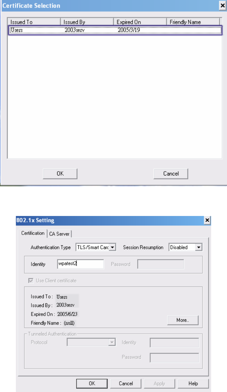
2. TLS / Smart Card:
i. Authentication type chooses TLS / Smart Card, TLS only need identity that is
wpatest2 for server authentication.
ii. TLS must use client certificate. Click more to choose certificate.
- 45 -
iii. Certificate page will pop up; choose a certificate for server authentication.
iv. Display certificate information in use client certificate page.
- 46 -
v. Click OK. The result will look like the below figure.
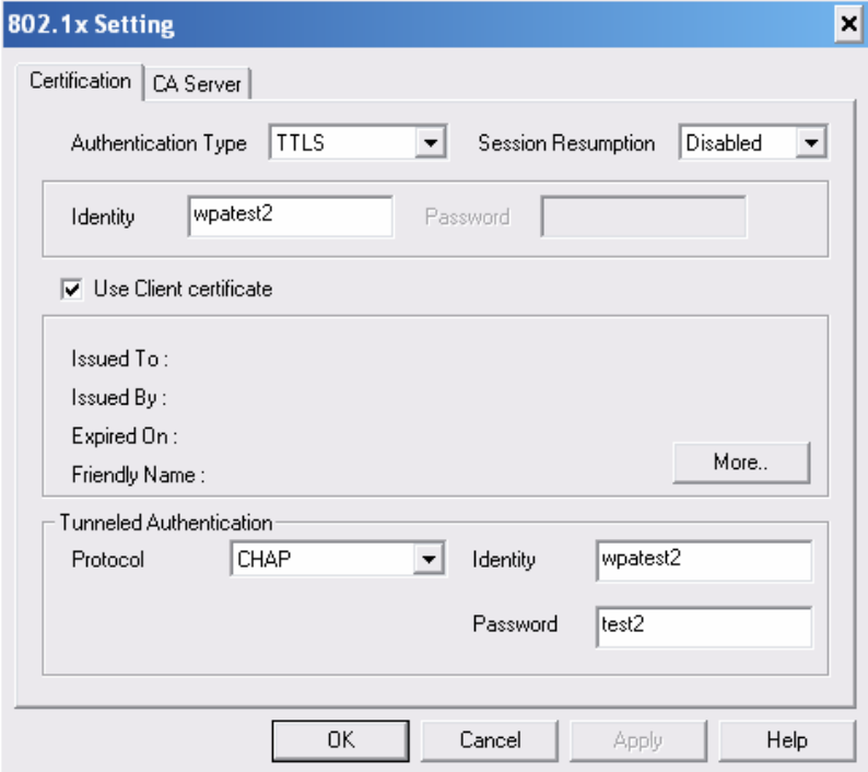
3. TTLS:
i. Authentication type chooses TTLS, identity is wpatest2. Protocol chooses CHAP for
tunnel authentication, tunnel identity is wpatest2 and tunnel password is test2. Those
setting are same as our intended AP’s setting.
- 47 -
ii. Click OK. The result will look like the below figure.
- 48 -
4. MD5:
i. Authentication type chooses MD5, MD5 only need identity and password that are
wpatest2 and test2 for server authentication.
ii. Click OK. The result will look like the below figure.
- 49 -
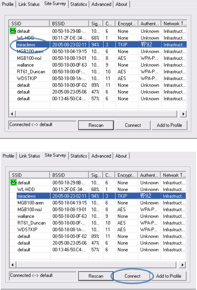
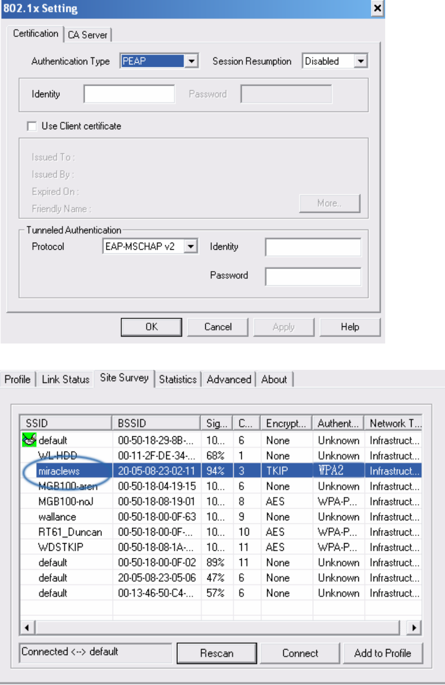
4-7 Configure connection with WPA2 by 802.1x setting
1. Select A.P with WPA2 authentication mode.
2. Click CONNECT or double click the intended network.
- 50 -
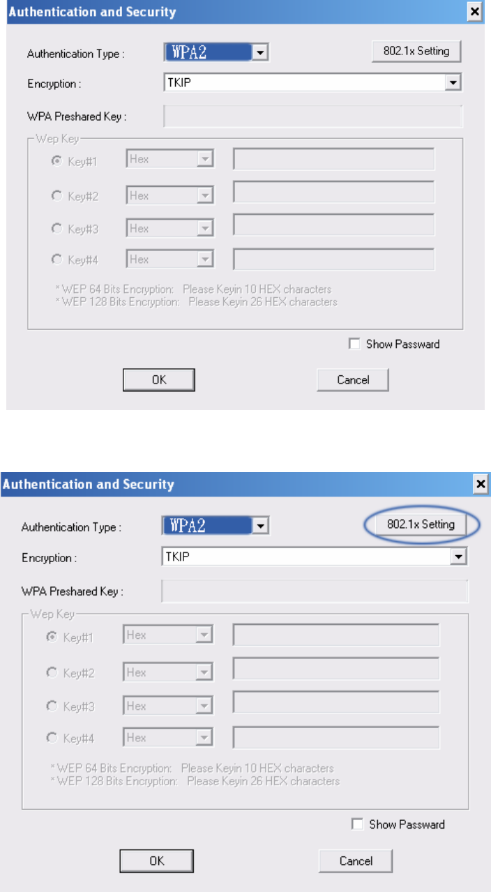
3. Authentication & Security page will pop up. TKIP, AES and Both (TKIP+AES) security are
support.
*If AP setup security to 〝Both 〞(TKIP + AES), system define is AES that security is severely.
4. Click 802.1x setting.
- 51 -
5. 802.1x setting page will pop up.
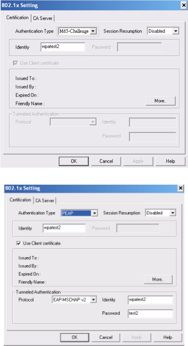
6. Authentication type and setting method:
1. PEAP:
i. Authentication type chooses PEAP, key identity into wpatest2. Protocol chooses
EAP-MSCHAP v2 for tunnel authentication, tunnel identity is wpatest2 and tunnel
password is test2. Those setting are same as our intended AP’s setting.
- 52 -
ii. Click OK. The result will look like the below figure.
- 53 -
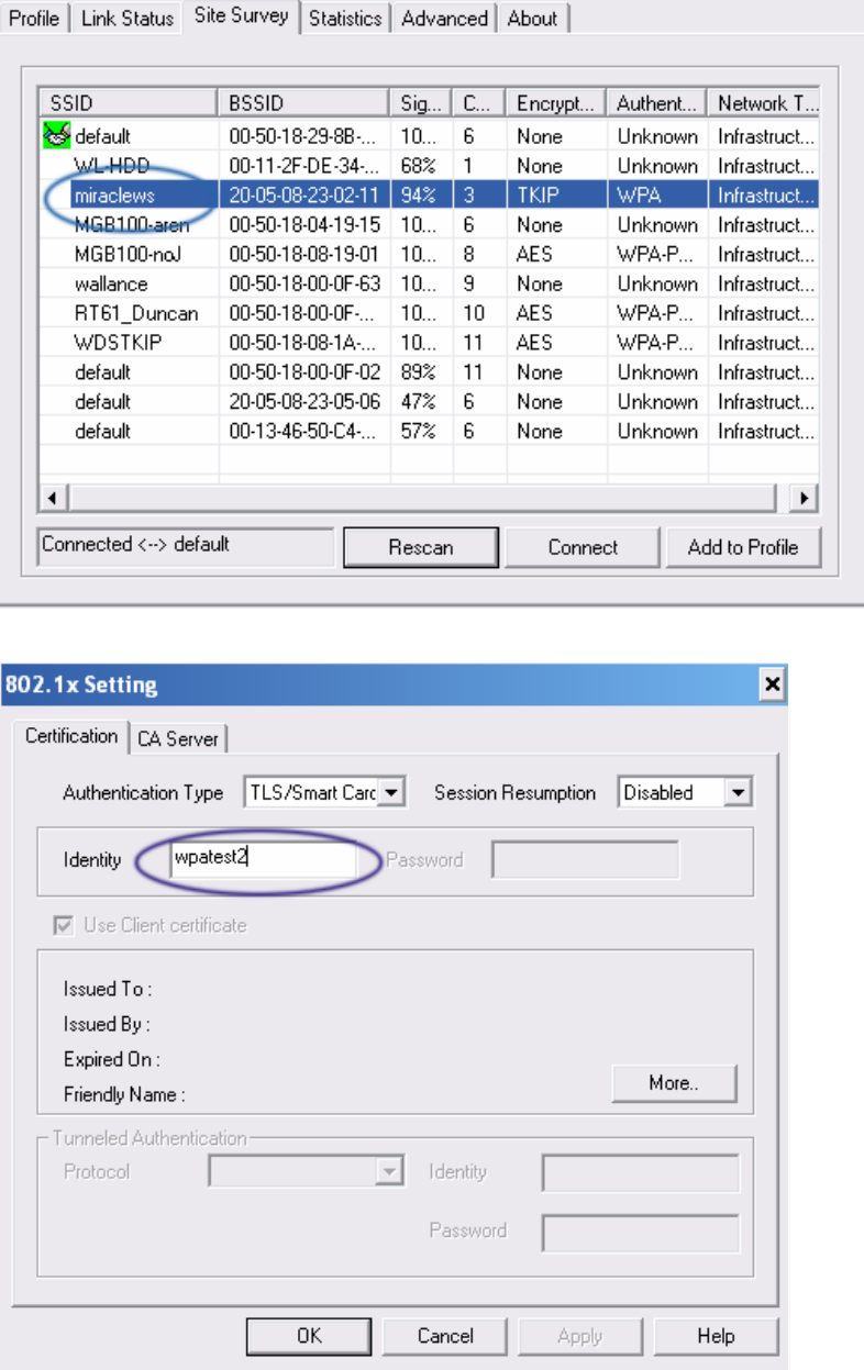
2. TLS / Smart Card:
i. Authentication type chooses TLS / Smart Card, TLS only need identity that is
wpatest2 for server authentication.
ii. TLS must use client certificate. Click more to choose certificate.
- 54 -
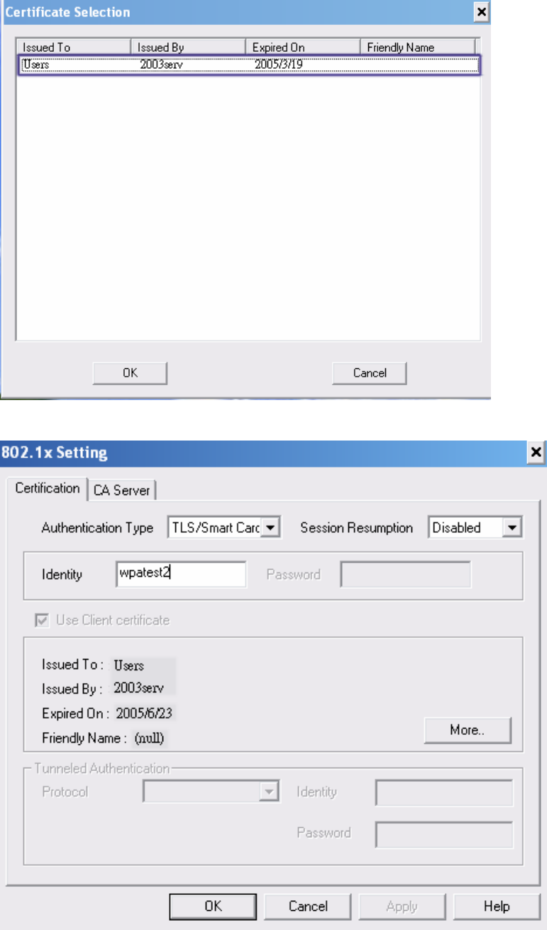
iii. Certificate page will pop up; choose a certificate for server authentication.
iv. Display certificate information in use client certificate page.
- 55 -
v. Click OK. The result will look like the below figure.
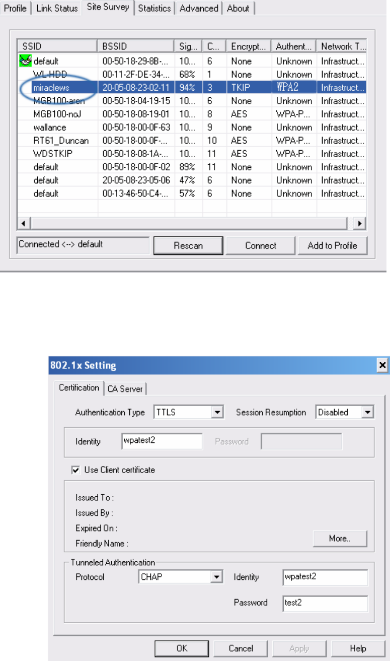
3. TTLS:
i. Authentication type chooses TTLS, identity is wpatest2. Protocol chooses CHAP for
tunnel authentication, tunnel identity is wpatest2 and tunnel password is test2. Those
setting are same as our intended AP’s setting.
- 56 -
ii. Click OK. The result will look like the below figure.
4. MD5:
i. Authentication type chooses MD5, MD5 only need identity and password that are
wpatest2 and test2 for server authentication.

- 57 -
ii. Click OK. The result will look like the below figure.