Advance Multimedia Internet Technology WUC128 802.11 b/g Wireless Broadband Router User Manual WUC128 041019
Advance Multimedia Internet Technology Inc. 802.11 b/g Wireless Broadband Router WUC128 041019
Contents
- 1. User Manual 1 of 2
- 2. User Manual 2 of 2
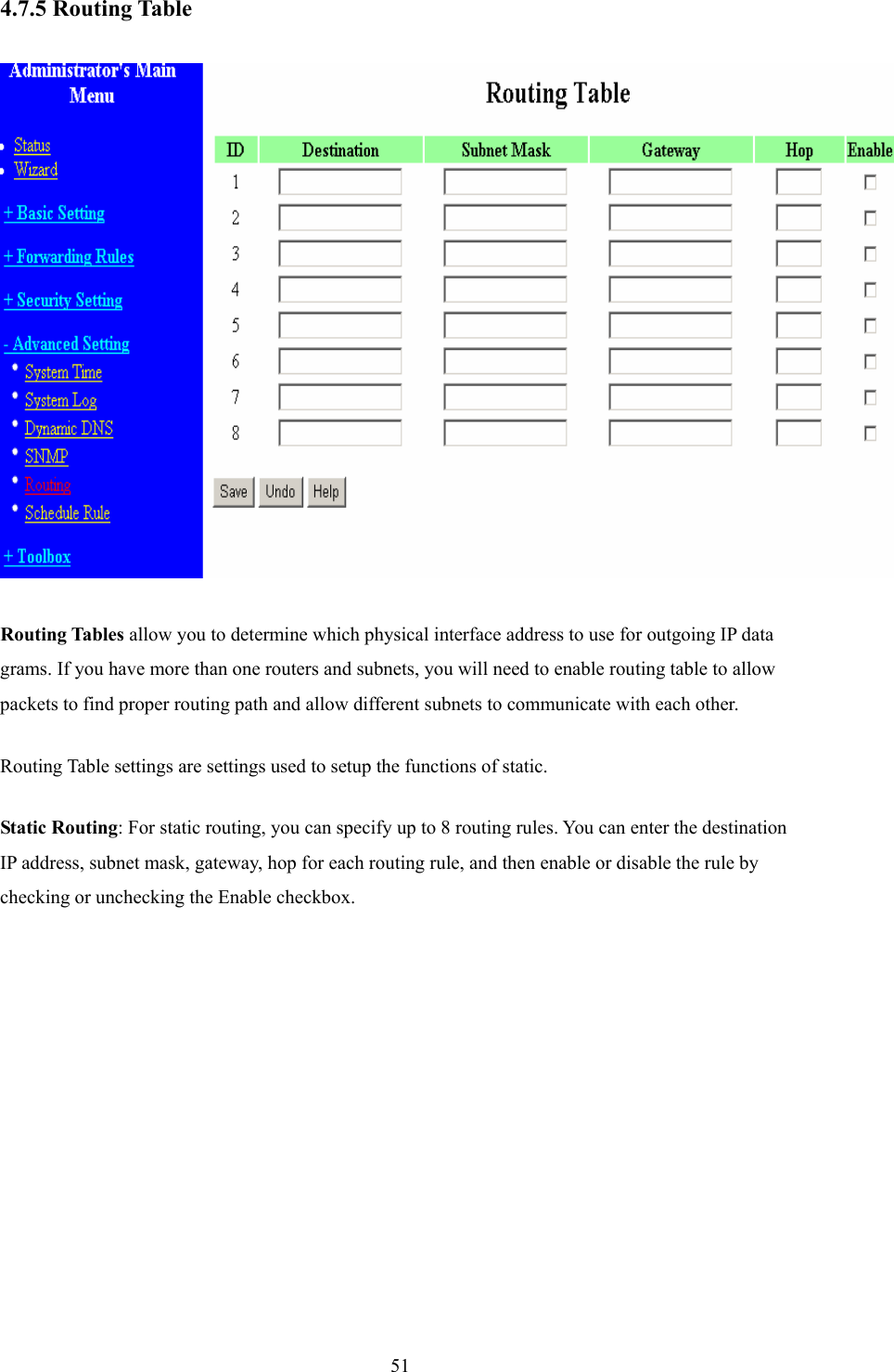
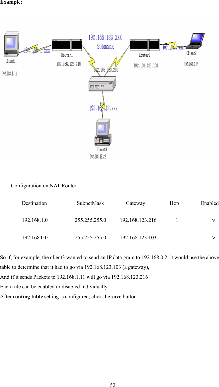
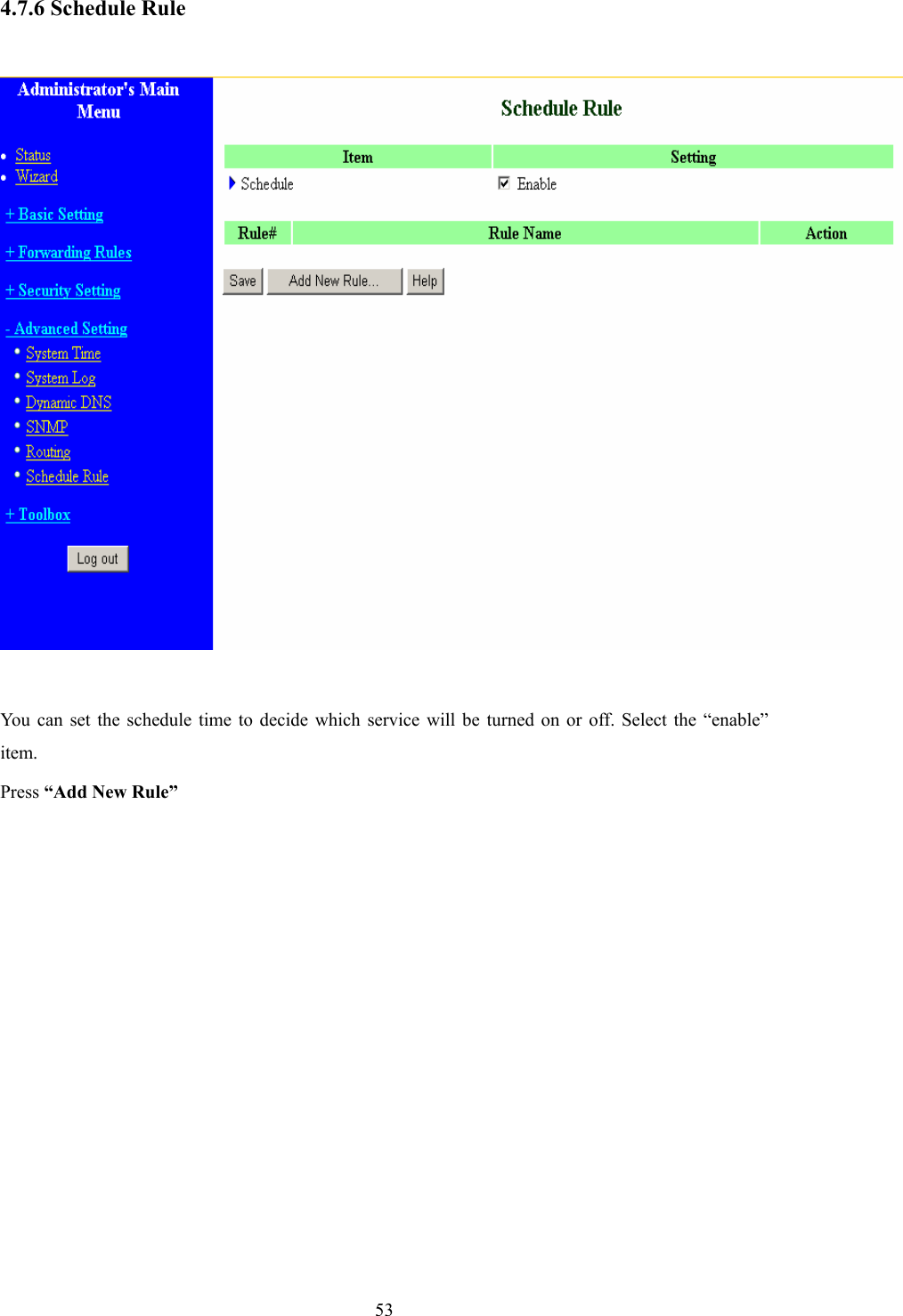
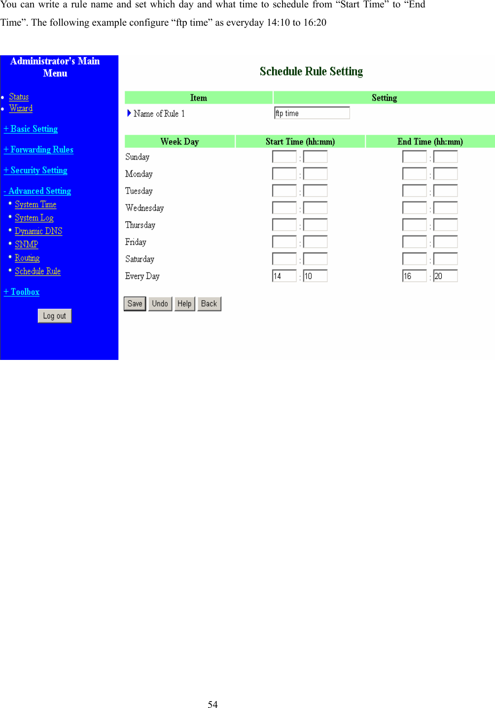
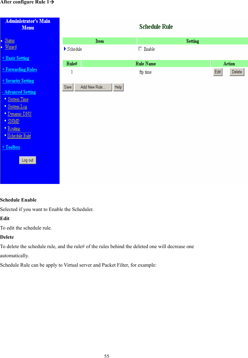
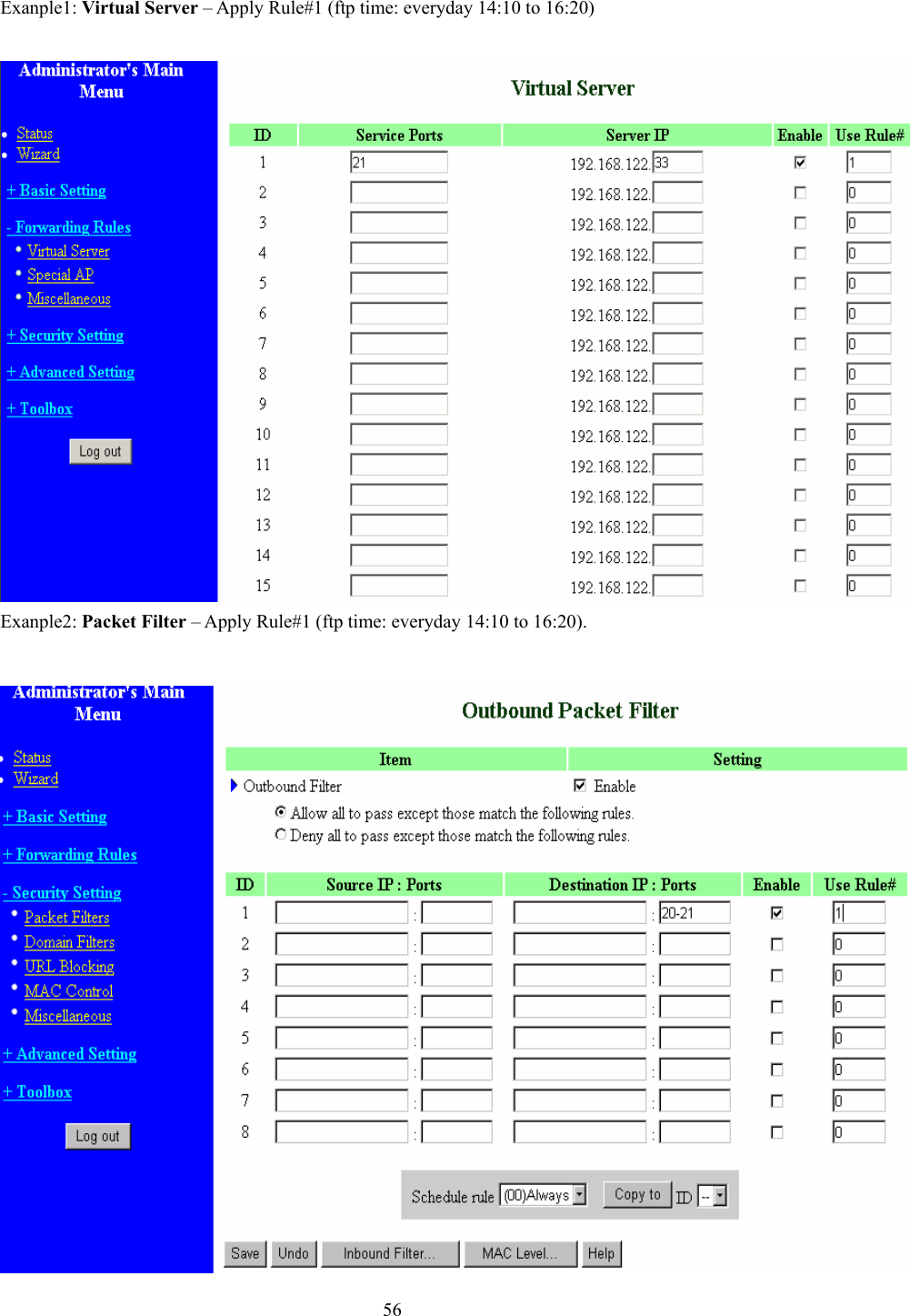
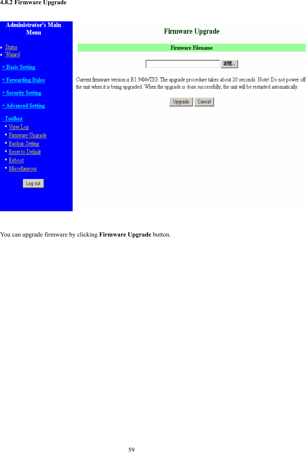
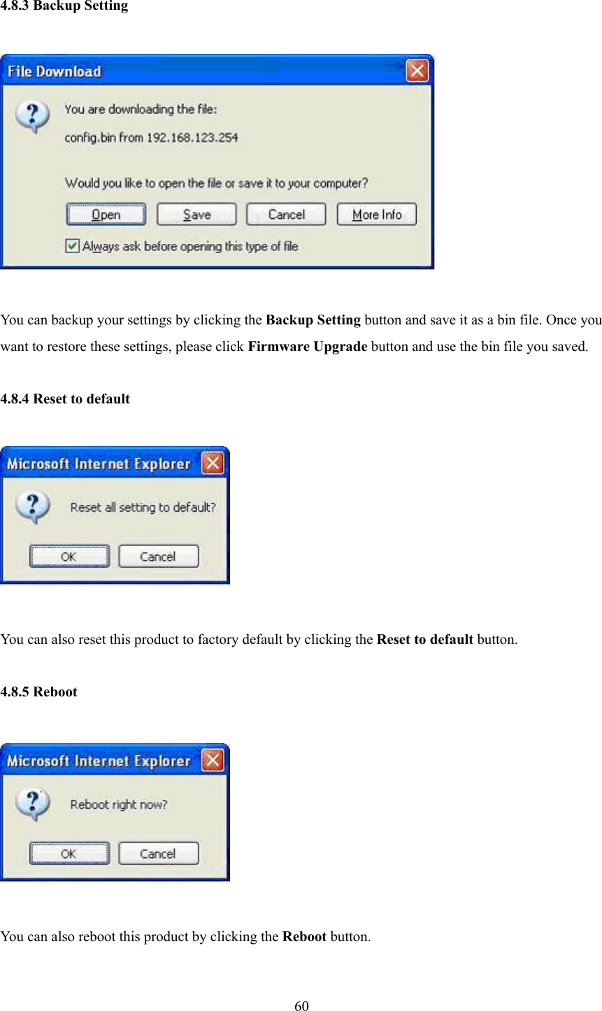
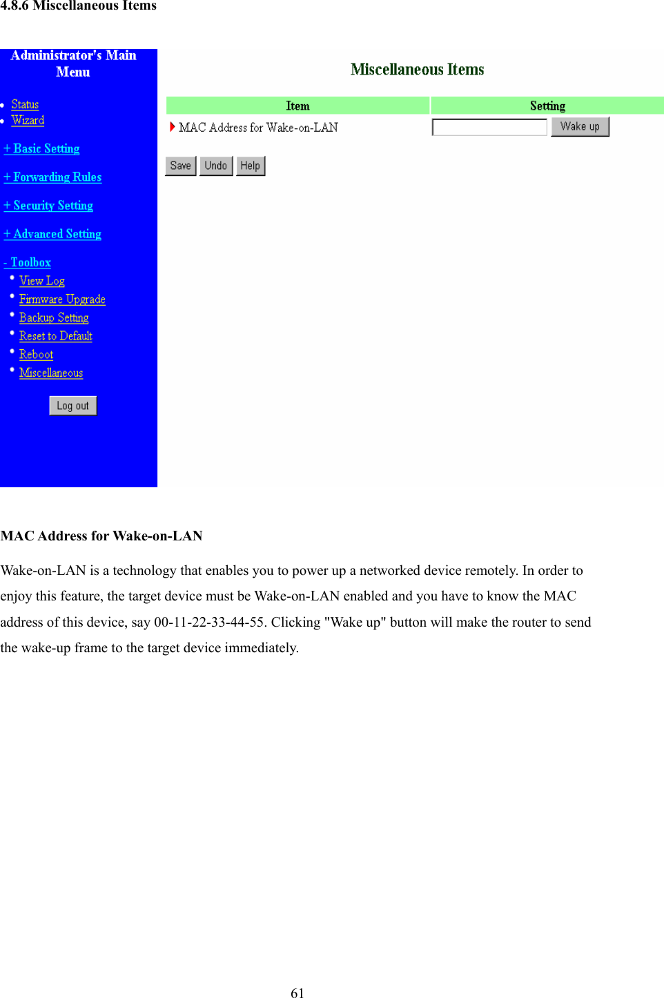
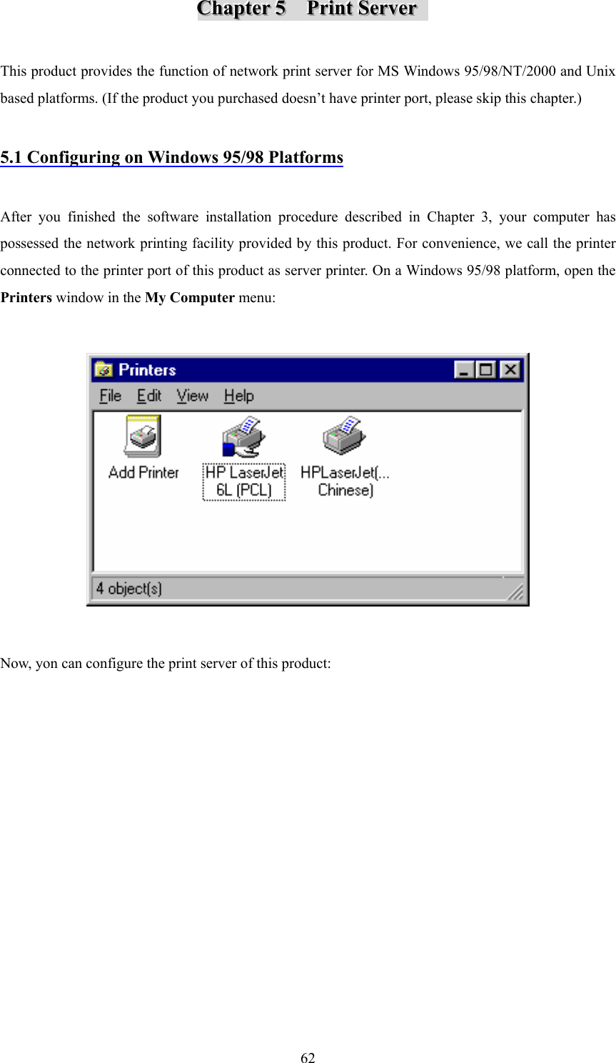
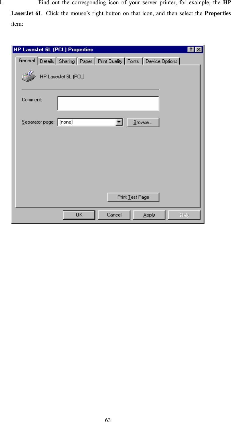
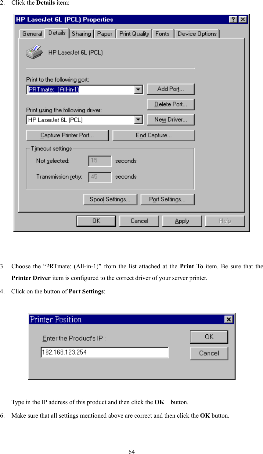
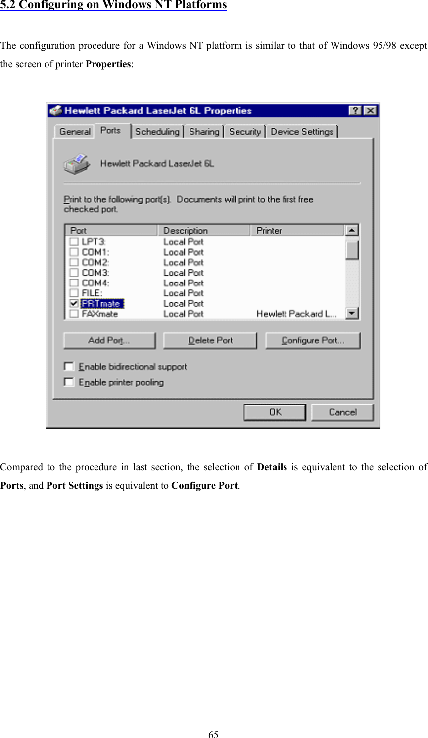
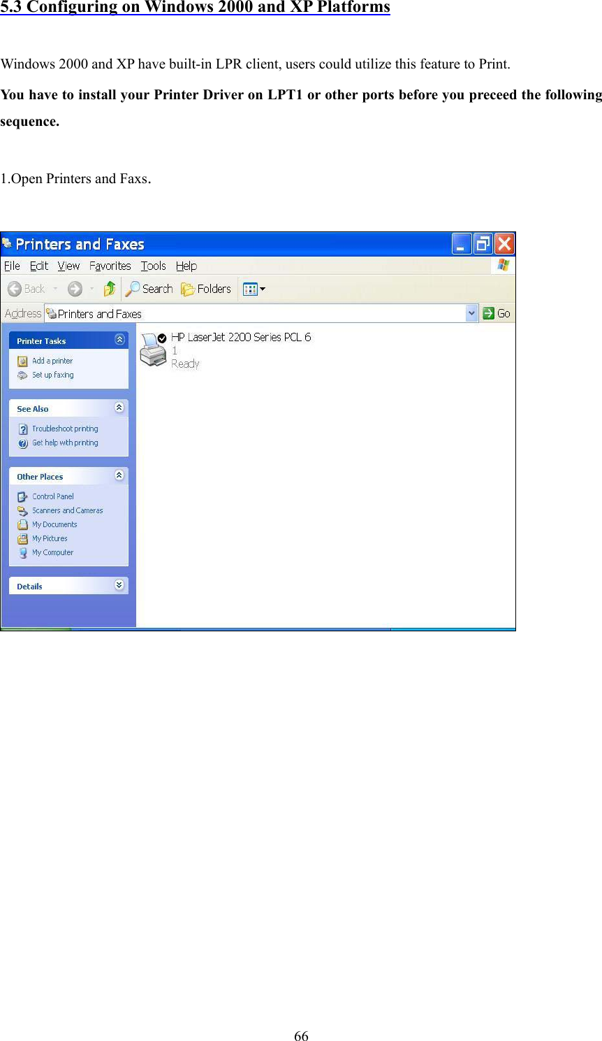
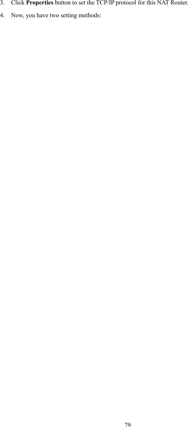
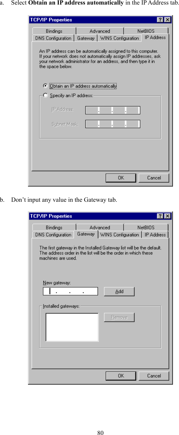
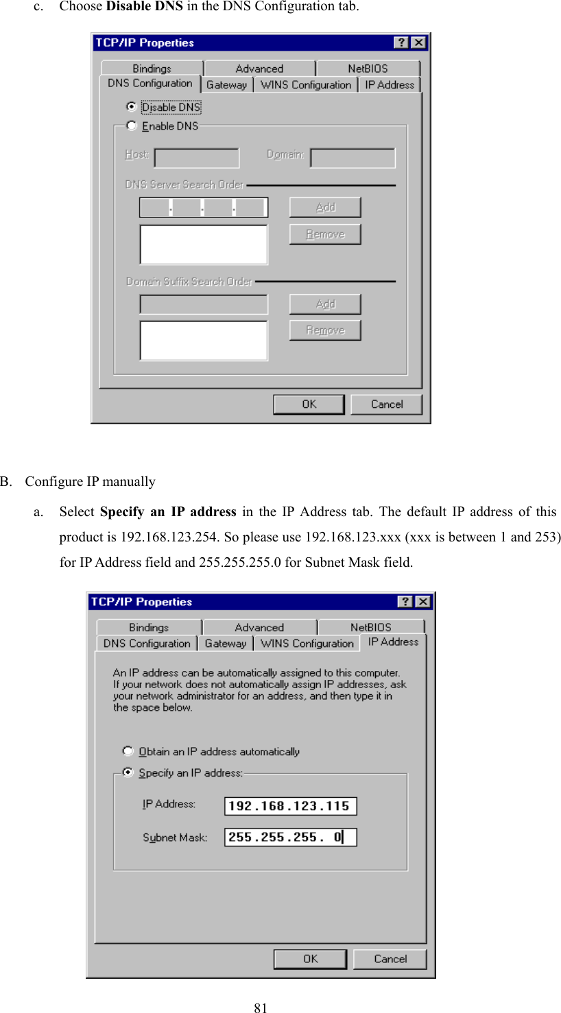
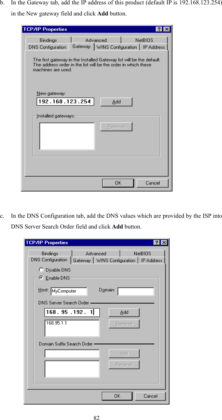
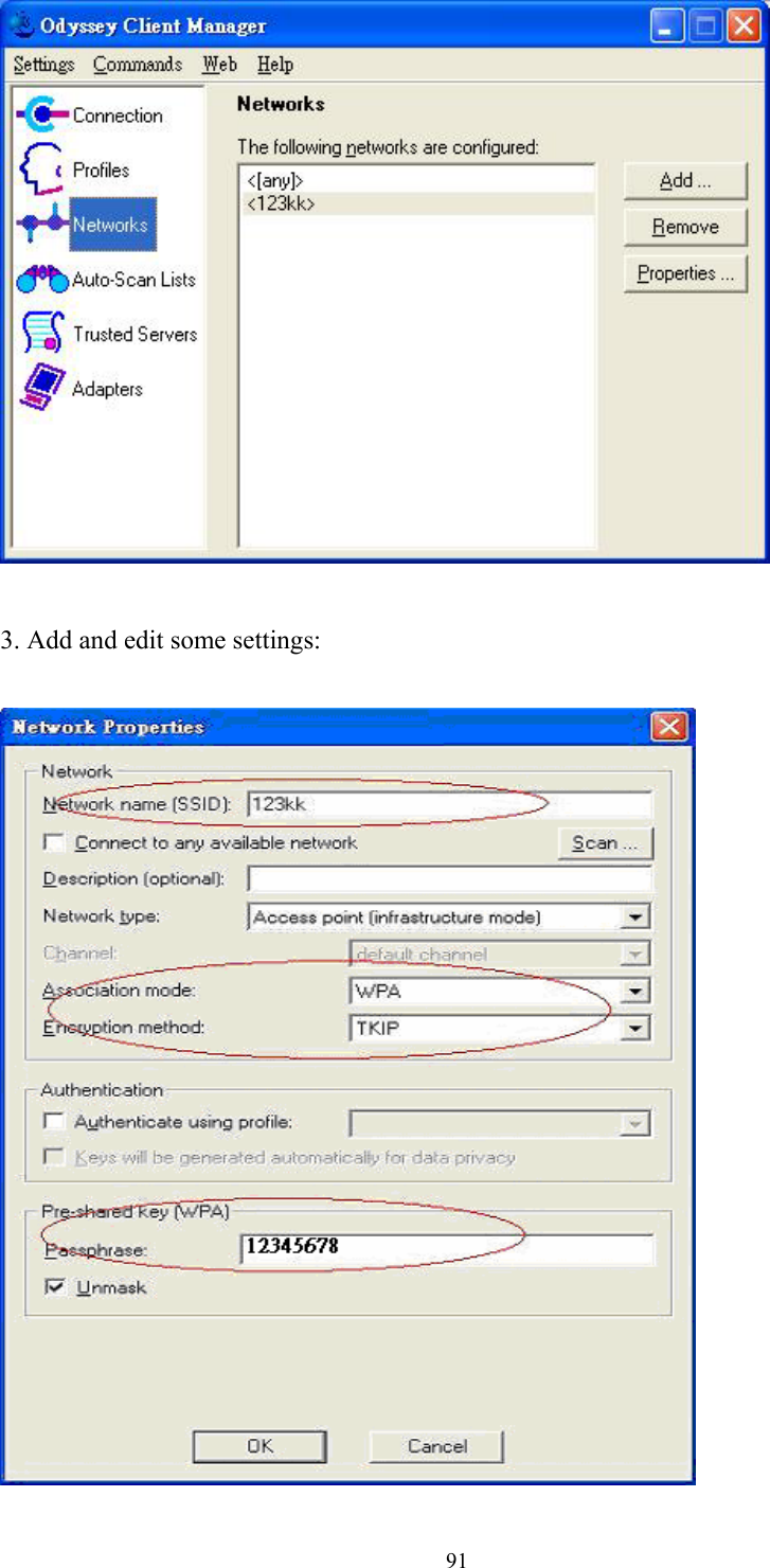
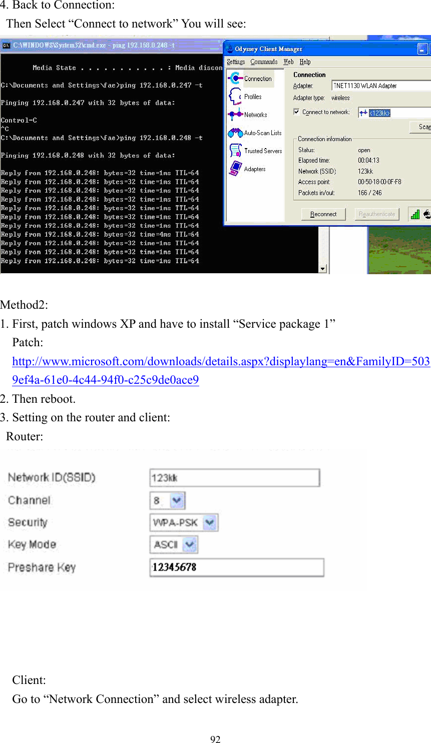
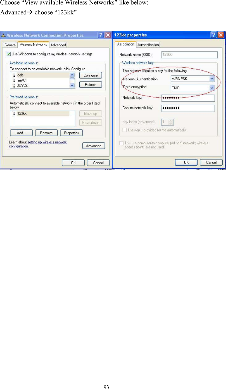
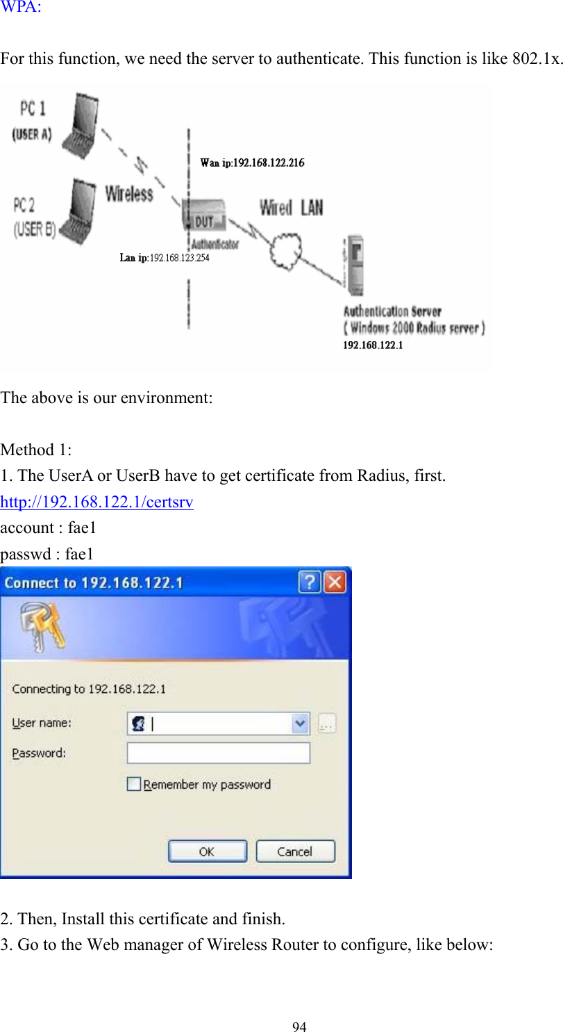
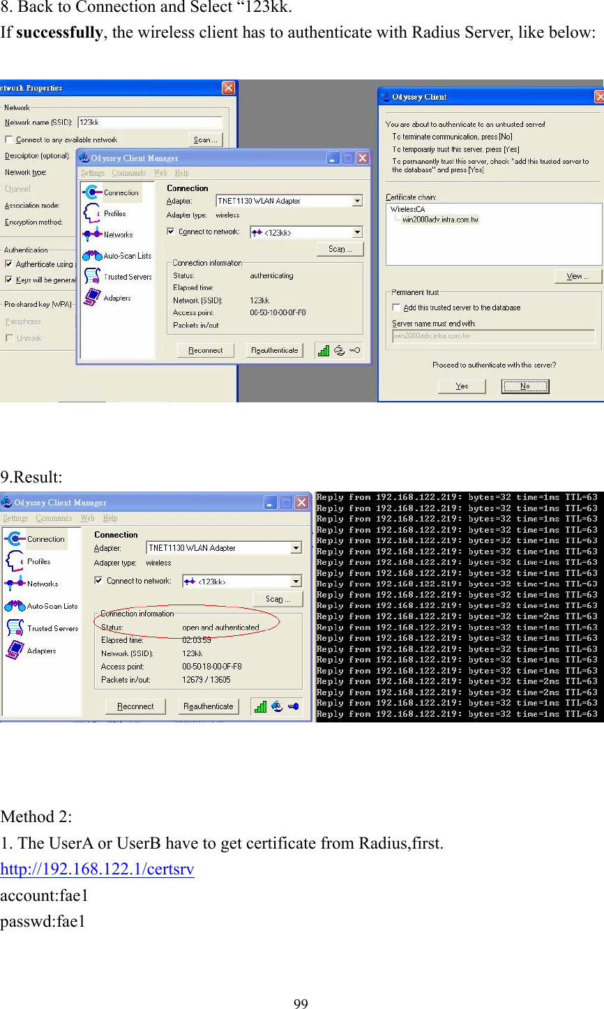
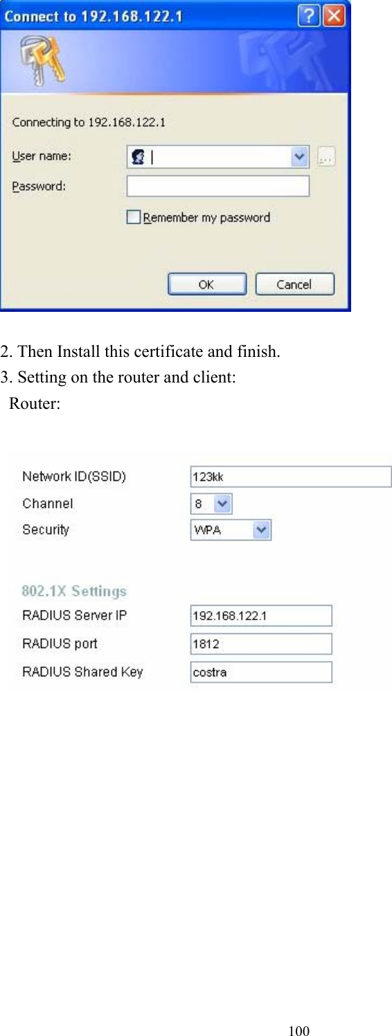
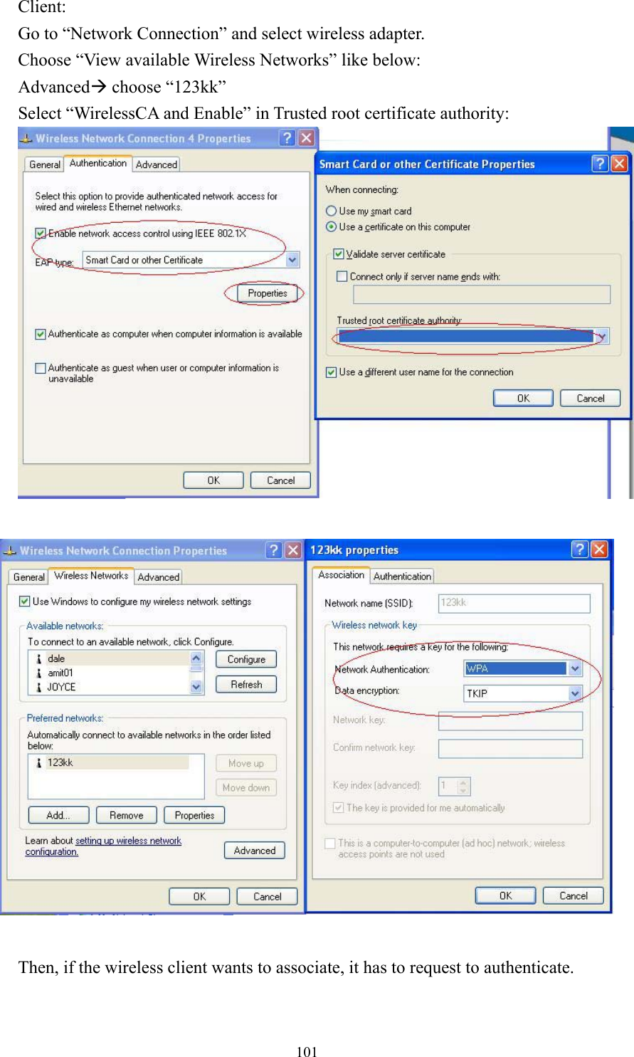
User Manual 2 of 2