Advance Multimedia Internet Technology WUC128 802.11 b/g Wireless Broadband Router User Manual WUC128 041019
Advance Multimedia Internet Technology Inc. 802.11 b/g Wireless Broadband Router WUC128 041019
Contents
- 1. User Manual 1 of 2
- 2. User Manual 2 of 2
User Manual 2 of 2
51
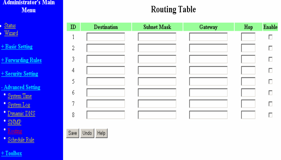
4.7.5 Routing Table
Routing Tables allow you to determine which physical interface address to use for outgoing IP data
grams. If you have more than one routers and subnets, you will need to enable routing table to allow
packets to find proper routing path and allow different subnets to communicate with each other.
Routing Table settings are settings used to setup the functions of static.
Static Routing: For static routing, you can specify up to 8 routing rules. You can enter the destination
IP address, subnet mask, gateway, hop for each routing rule, and then enable or disable the rule by
checking or unchecking the Enable checkbox.
52
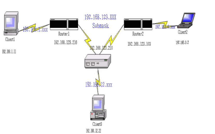
Example:
Configuration on NAT Router
Destination SubnetMask Gateway Hop Enabled
192.168.1.0 255.255.255.0 192.168.123.216 1 ˇ
192.168.0.0 255.255.255.0 192.168.123.103 1 ˇ
So if, for example, the client3 wanted to send an IP data gram to 192.168.0.2, it would use the above
table to determine that it had to go via 192.168.123.103 (a gateway),
And if it sends Packets to 192.168.1.11 will go via 192.168.123.216
Each rule can be enabled or disabled individually.
After routing table setting is configured, click the save button.
53
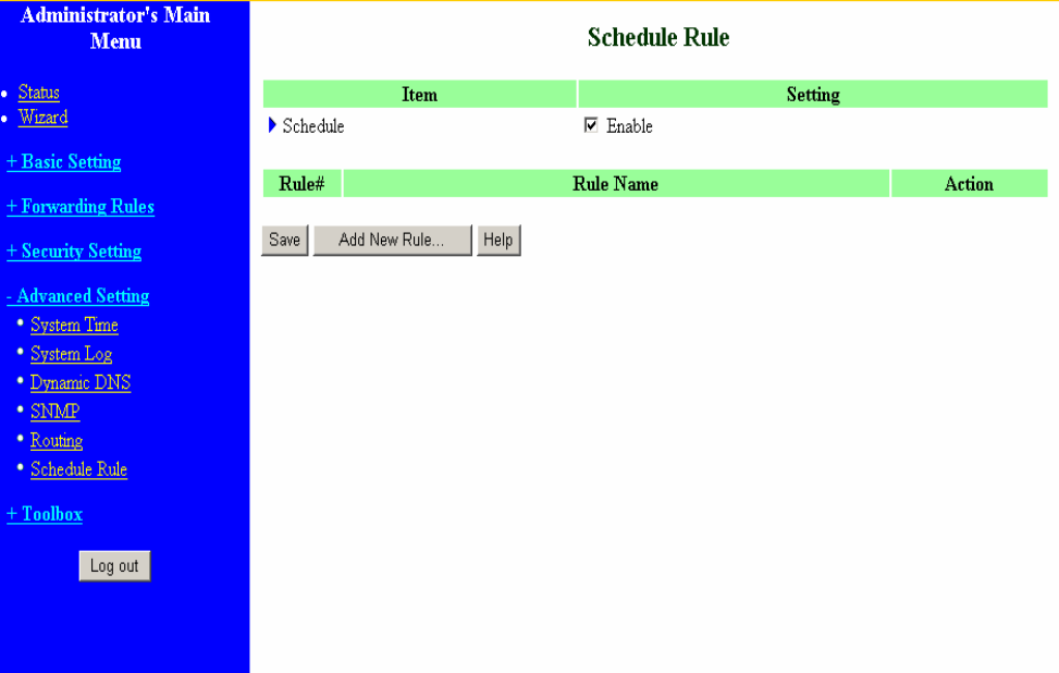
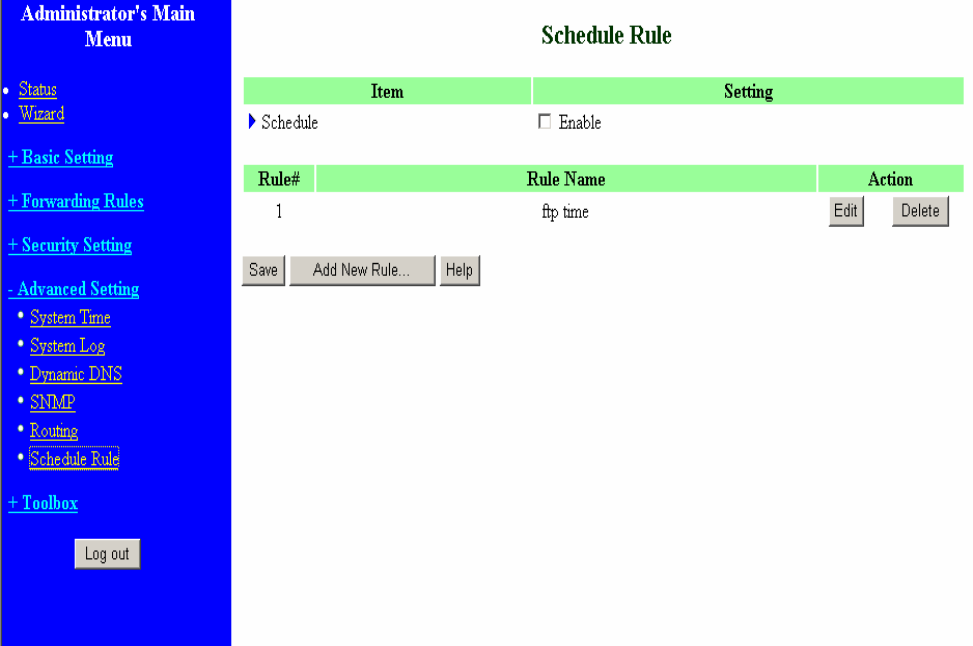
4.7.6 Schedule Rule
You can set the schedule time to decide which service will be turned on or off. Select the “enable”
item.
Press “Add New Rule”
54
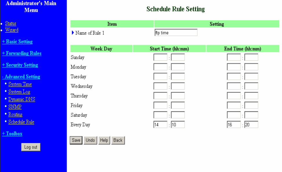
You can write a rule name and set which day and what time to schedule from “Start Time” to “End
Time”. The following example configure “ftp time” as everyday 14:10 to 16:20
55
After configure Rule 1Æ
Schedule Enable
Selected if you want to Enable the Scheduler.
Edit
To edit the schedule rule.
Delete
To delete the schedule rule, and the rule# of the rules behind the deleted one will decrease one
automatically.
Schedule Rule can be apply to Virtual server and Packet Filter, for example:
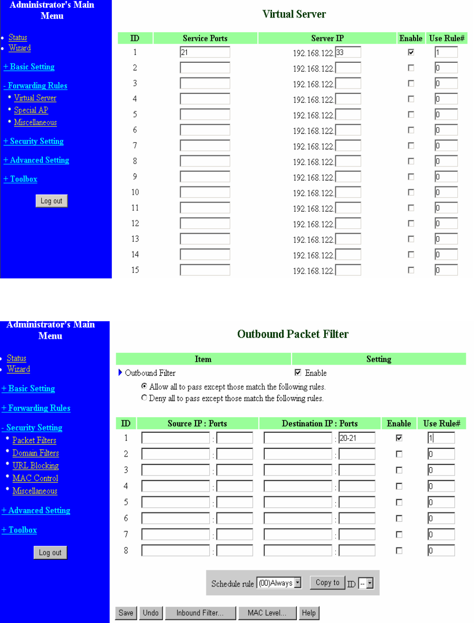
56
Exanple1: Virtual Server – Apply Rule#1 (ftp time: everyday 14:10 to 16:20)
Exanple2: Packet Filter – Apply Rule#1 (ftp time: everyday 14:10 to 16:20).
57
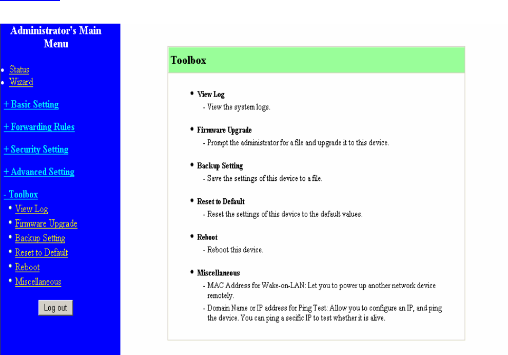
4.8 Toolbox
58
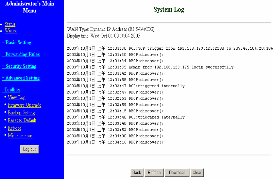
4.8.1 System Log
You can View system log by clicking the View Log button
59
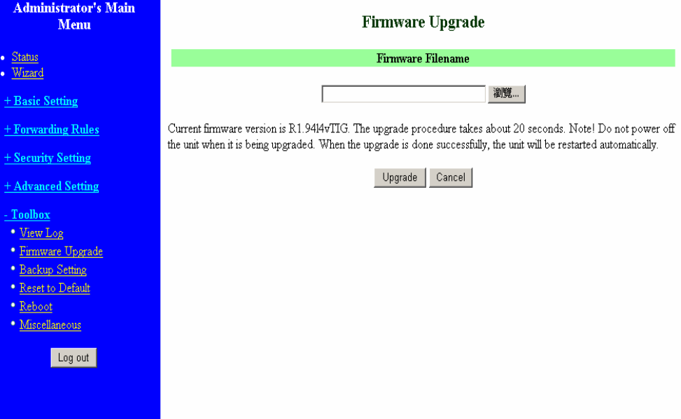
4.8.2 Firmware Upgrade
You can upgrade firmware by clicking Firmware Upgrade button.
60
4.8.3 Backup Setting
You can backup your settings by clicking the Backup Setting button and save it as a bin file. Once you
want to restore these settings, please click Firmware Upgrade button and use the bin file you saved.
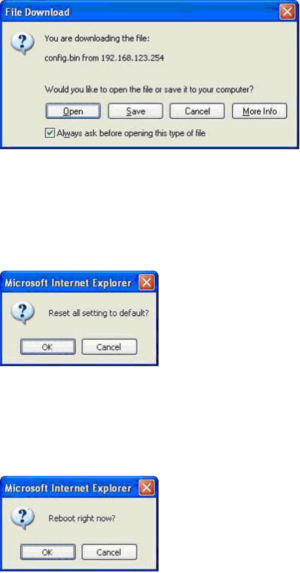
4.8.4 Reset to default
You can also reset this product to factory default by clicking the Reset to default button.
4.8.5 Reboot
You can also reboot this product by clicking the Reboot button.
61
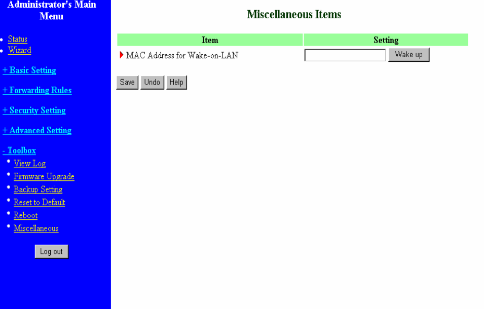
4.8.6 Miscellaneous Items
MAC Address for Wake-on-LAN
Wake-on-LAN is a technology that enables you to power up a networked device remotely. In order to
enjoy this feature, the target device must be Wake-on-LAN enabled and you have to know the MAC
address of this device, say 00-11-22-33-44-55. Clicking "Wake up" button will make the router to send
the wake-up frame to the target device immediately.
62
C
C
Ch
h
ha
a
ap
p
pt
t
te
e
er
r
r
5
5
5
P
P
Pr
r
ri
i
in
n
nt
t
t
S
S
Se
e
er
r
rv
v
ve
e
er
r
r
This product provides the function of network print server for MS Windows 95/98/NT/2000 and Unix
based platforms. (If the product you purchased doesn’t have printer port, please skip this chapter.)
5.1 Configuring on Windows 95/98 Platforms
After you finished the software installation procedure described in Chapter 3, your computer has
possessed the network printing facility provided by this product. For convenience, we call the printer
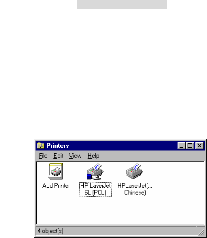
connected to the printer port of this product as server printer. On a Windows 95/98 platform, open the
Printers window in the My Computer menu:
Now, yon can configure the print server of this product:
63
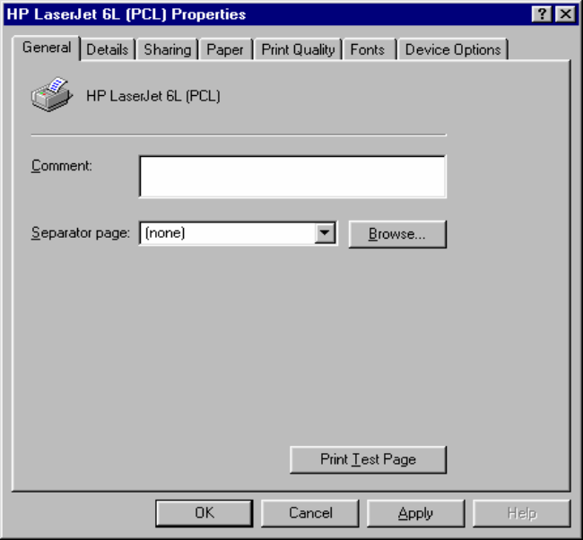
1. Find out the corresponding icon of your server printer, for example, the HP
LaserJet 6L. Click the mouse’s right button on that icon, and then select the Properties
item:
64
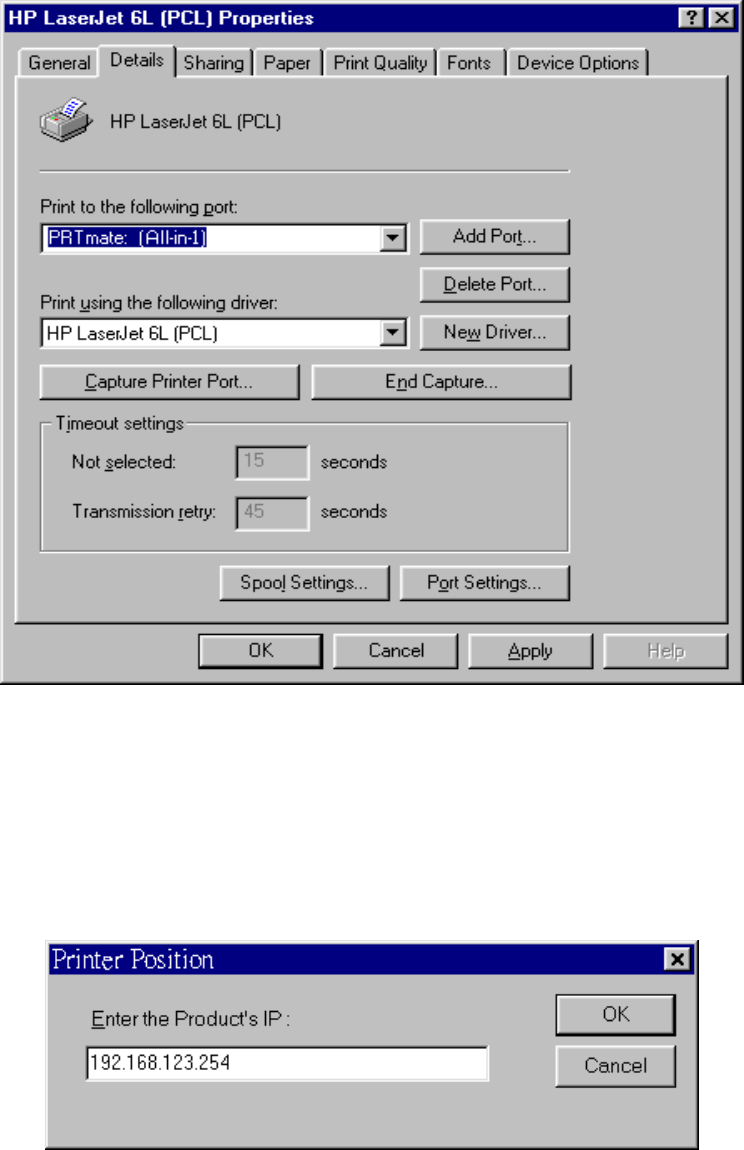
2. Click the Details item:
3. Choose the “PRTmate: (All-in-1)” from the list attached at the Print To item. Be sure that the
Printer Driver item is configured to the correct driver of your server printer.
4. Click on the button of Port Settings:
Type in the IP address of this product and then click the OK button.
6. Make sure that all settings mentioned above are correct and then click the OK button.
65
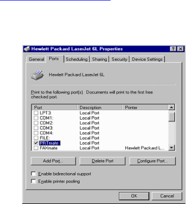
5.2 Configuring on Windows NT Platforms
The configuration procedure for a Windows NT platform is similar to that of Windows 95/98 except
the screen of printer Properties:
Compared to the procedure in last section, the selection of Details is equivalent to the selection of
Ports, and Port Settings is equivalent to Configure Port.
66
5.3 Configuring on Windows 2000 and XP Platforms
Windows 2000 and XP have built-in LPR client, users could utilize this feature to Print.
You have to install your Printer Driver on LPT1 or other ports before you preceed the following
sequence.
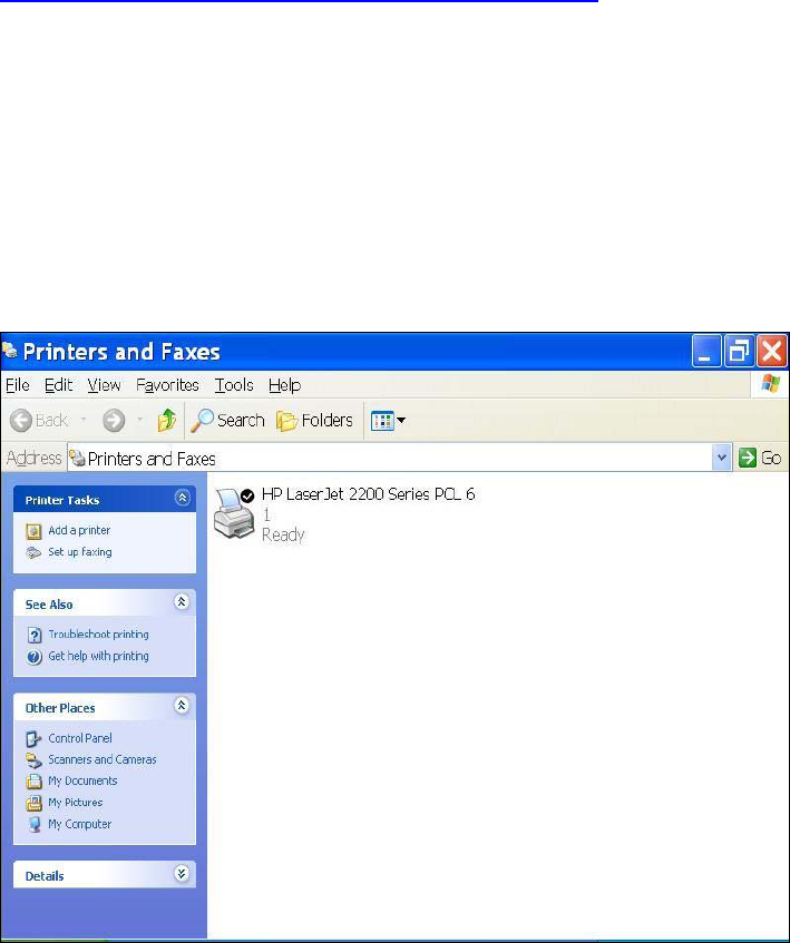
1.Open Printers and Faxs.
67
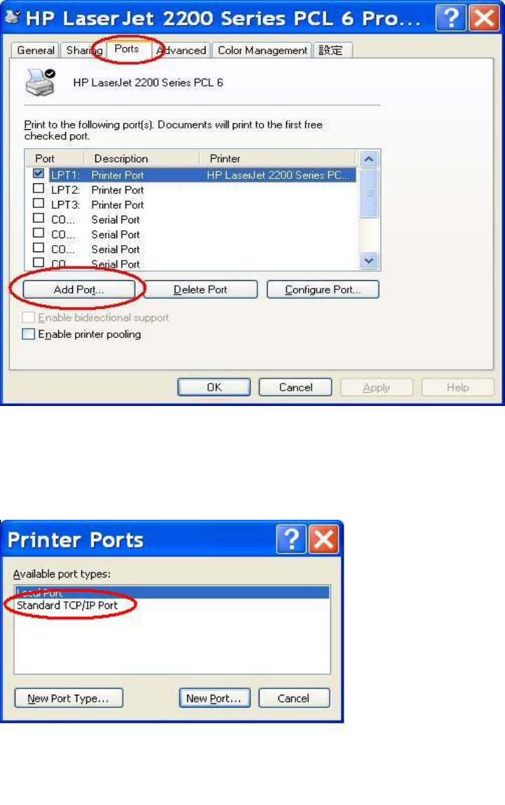
2.Select “Ports” page, Click “Add Port…”
3. Select “Standard TCP/IP Port”, and then click “New Port…”
68
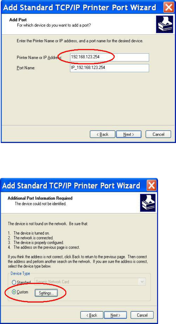
4.Click Next and then provide the following information:
Type address of server providing LPD that is our NAT device:192.168.123.254
1. Select Custom, then click “Settings…”
69
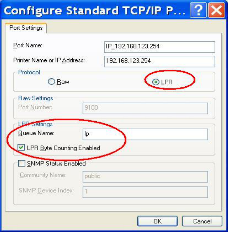
6.Select “LPR”, type ” lp“ lowercase letter in “Queue Name:”
And enable “LPR Byte Counting Enabled”.
70
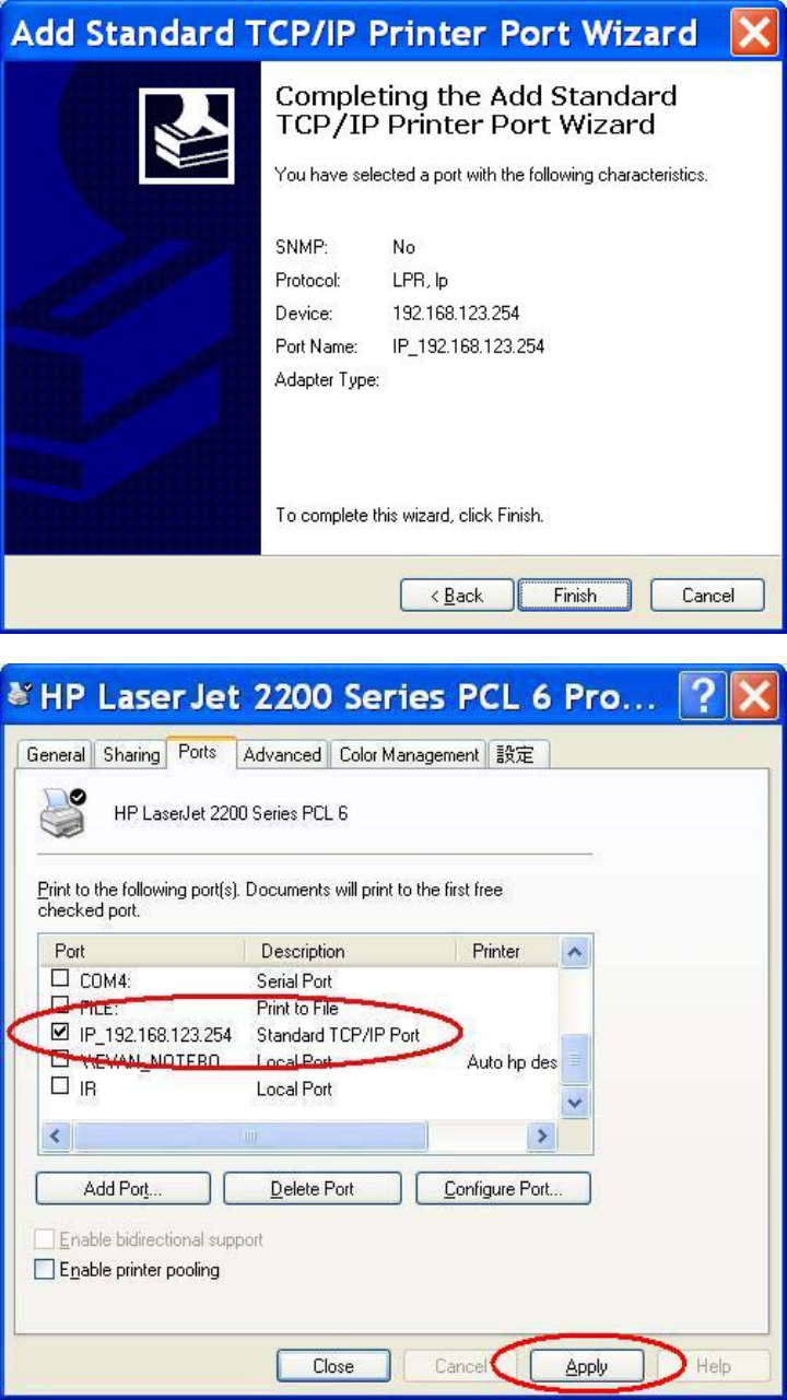
7.Apply your settings
71
5.4 Configuring on Unix-like based Platforms
Please follow the traditional configuration procedure on Unix platforms to setup the print server of this
product. The printer name is “lp.”
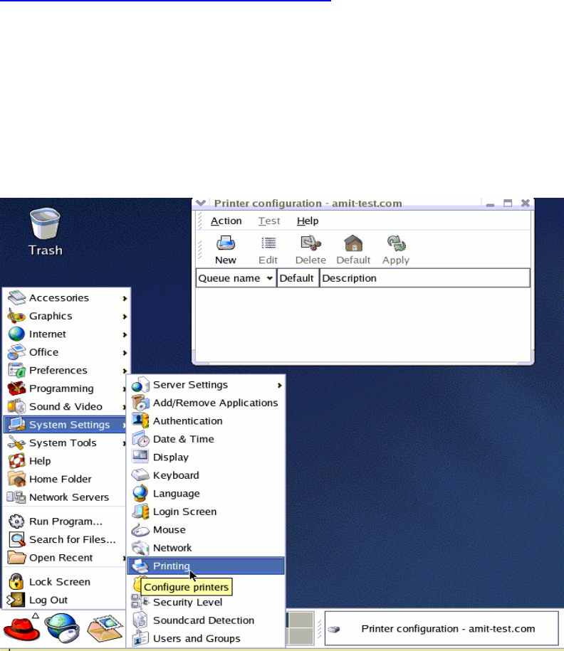
In X-Windows, for example, In Redhat Platforms,
Please follow the below steps to configure your printer on Red Hat 9.0.1. Start from the Red Hat--->
System Setting---> Printing.
72
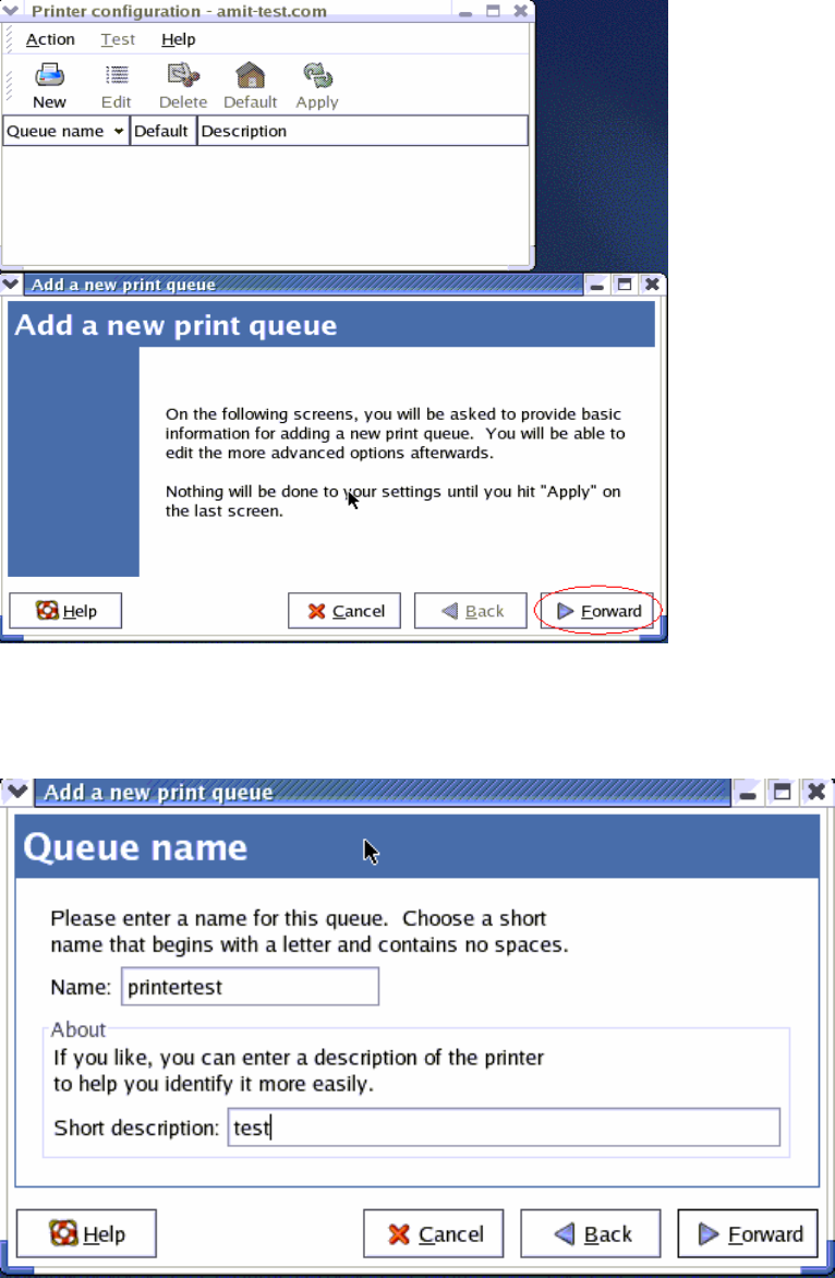
2. Click New---> Forward.
1. Enter the Pinter Name, Comments then forward.
73
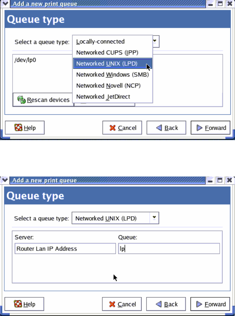
4. Select LPD protocol and then forward.
5. Enter Router LAN IP Address and the queue name "lp". Then forward.
74
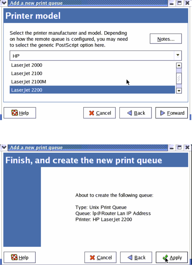
6. Select the Printer Brand and Model Name. Then Forward.
7. Click Apply to finish setup.
8. At last you must click Apply on the toolbox to make the change take effective.
75
In Command Mode:
Linux has built-in LPR client ,You can utilize it for printing.
You can manual set it or via the tool "printtool" in X-windows.
PS: The spool name is "lp"------all lowercase letter.
Below is my setting.
/etc/printcap
------------------------------------------------------------------------------
lp:\
:sd=/var/spool/lpd/lp:\
:mx#0:\
:sh:\
:rm=192.168.123.254:\
:rp=lp:\ -------------->key point
:if=/var/spool/lpd/lp/filter:
------------------------------------------------------------------------------
Then add the corresponding directory
#mkdir /var/spool/lpd/lp
Too see the detail ,please refer to the online manual in linux.
#man printcap
76
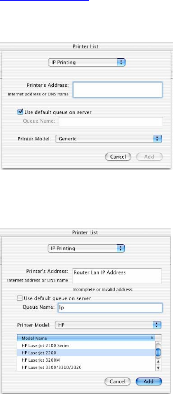
5.5 Configuring on Apple PC
1.First, go to Printer center (Printer list) and add printer
2.Choose IP print and setup printer ip address (router Lan ip address).
3.Disable “Default Queue of Server.” And fill in ‘ lp ‘ in Queue name item.
4.Printer Model: Choose “General” or Printer as below.
77
A
A
Ap
p
pp
p
pe
e
en
n
nd
d
di
i
ix
x
x
A
A
A
T
T
TC
C
CP
P
P/
/
/I
I
IP
P
P
C
C
Co
o
on
n
nf
f
fi
i
ig
g
gu
u
ur
r
ra
a
at
t
ti
i
io
o
on
n
n
f
f
fo
o
or
r
r
W
W
Wi
i
in
n
nd
d
do
o
ow
w
ws
s
s
9
9
95
5
5/
/
/9
9
98
8
8
This section introduces you how to install TCP/IP protocol into your personal computer. And suppose
you have been successfully installed one network card on your personal computer. If not, please refer
to your network card manual. Moreover, the Section B.2 tells you how to set TCP/IP values for
working with this NAT Router correctly.
A.1 Install TCP/IP Protocol into Your PC
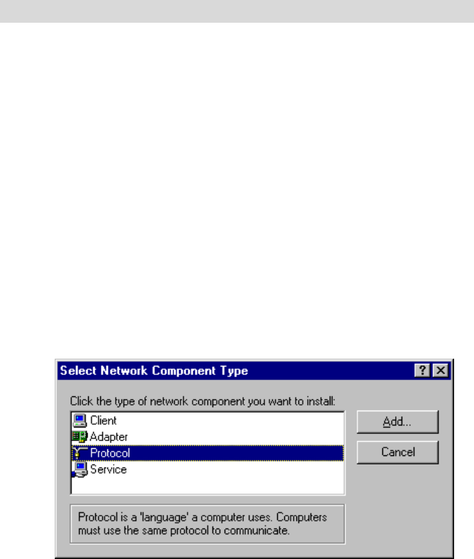
1. Click Start button and choose Settings, then click Control Panel.
2. Double click Network icon and select Configuration tab in the Network window.
3. Click Add button to add network component into your PC.
4. Double click Protocol to add TCP/IP protocol.
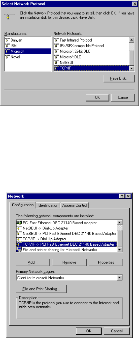
5. Select Microsoft item in the manufactures list. And choose TCP/IP in the Network Protocols.
Click OK button to return to Network window.
78
6. The TCP/IP protocol shall be listed in the Network window. Click OK to complete the install
procedure and restart your PC to enable the TCP/IP protocol.
A.2 Set TCP/IP Protocol for Working with NAT Router
1. Click Start button and choose Settings, then click Control Panel.
2. Double click Network icon. Select the TCP/IP line that has been associated to your network card
in the Configuration tab of the Network window.
79
3. Click Properties button to set the TCP/IP protocol for this NAT Router.
4. Now, you have two setting methods:
80
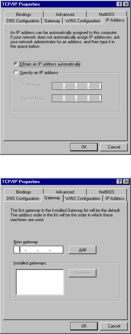
a. Select Obtain an IP address automatically in the IP Address tab.
b. Don’t input any value in the Gateway tab.
81
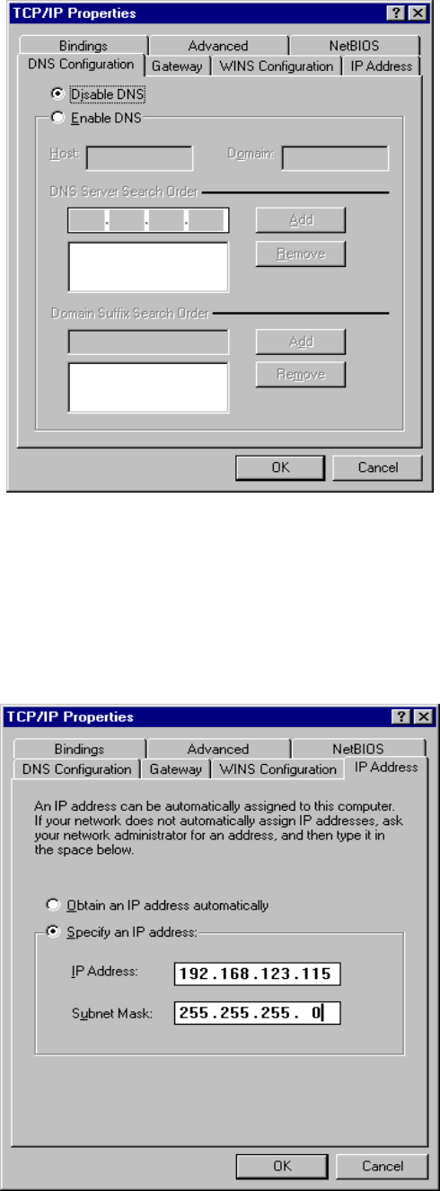
c. Choose Disable DNS in the DNS Configuration tab.
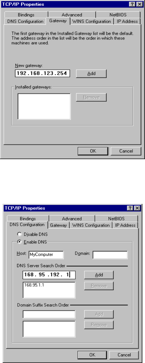
B. Configure IP manually
a. Select Specify an IP address in the IP Address tab. The default IP address of this
product is 192.168.123.254. So please use 192.168.123.xxx (xxx is between 1 and 253)
for IP Address field and 255.255.255.0 for Subnet Mask field.
82
b. In the Gateway tab, add the IP address of this product (default IP is 192.168.123.254)
in the New gateway field and click Add button.
c. In the DNS Configuration tab, add the DNS values which are provided by the ISP into
DNS Server Search Order field and click Add button.
83
A
A
Ap
p
pp
p
pe
e
en
n
nd
d
di
i
ix
x
x
B
B
B
8
8
80
0
02
2
2.
.
.1
1
1x
x
x
S
S
Se
e
et
t
tt
t
ti
i
in
n
ng
g
g
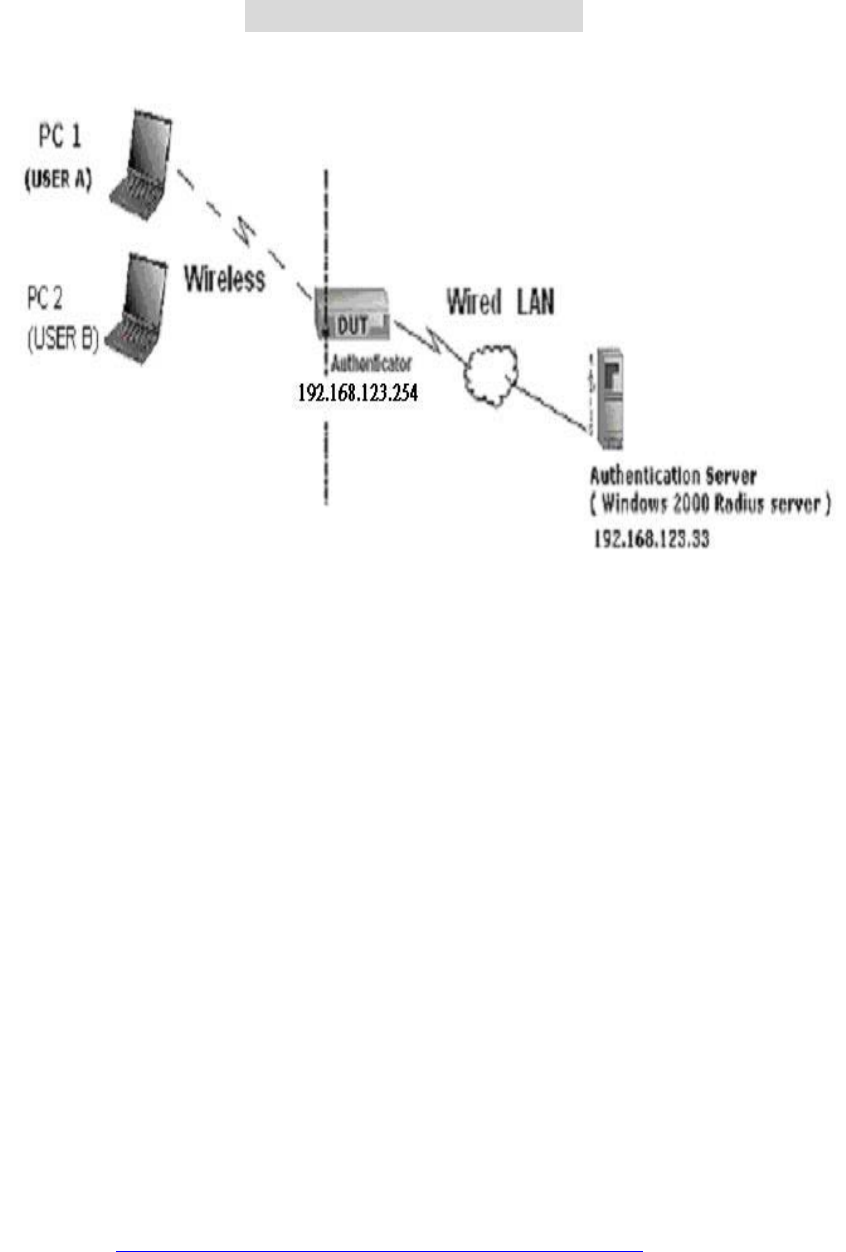
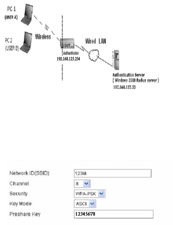
Figure 1: Testing Environment (Use Windows 2000 Radius Server)
1 Equipment Details
PC1:
Microsoft Windows XP Professional without Service Pack 1.
D-Link DWL-650+ wireless LAN adapter
Driver version: 3.0.5.0 (Driver date: 03.05.2003)
PC2:
Microsoft Windows XP Professional with Service Pack 1a.
Z-Com XI-725 wireless LAN USB adapter
Driver version: 1.7.29.0 (Driver date: 10.20.2001)
Authentication Server: Windows 2000 RADIUS server with Service Pack 3 and HotFix
Q313664.
Note. Windows 2000 RADIUS server only supports PEAP after upgrade to service pack
3 and HotFix Q313664 (You can get more information from
http://support.microsoft.com/default.aspx?scid=kb; en-us;313664)
2 DUT
Configuration:
84
1.Enable DHCP server.
2.WAN setting: static IP address.
3.LAN IP address: 192.168.123.254/24.
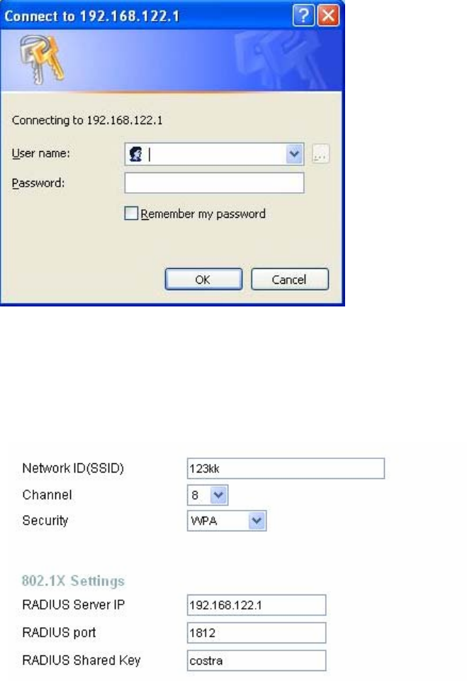
4.Set RADIUS server IP.
5.Set RADIUS server shared key.
6.Configure WEP key and 802.1X setting.
The following test will use the inbuilt 802.1X authentication method such as ,EAP_TLS,
PEAP_CHAPv2(Windows XP with SP1 only), and PEAP_TLS(Windows XP with SP1 only)
using the Smart Card or other Certificate of the Windows XP Professional.
3. DUT and Windows 2000 Radius Server Setup
3-1-1. Setup Windows 2000 RADIUS Server
We have to change authentication method to MD5_Challenge or using smart
card or other certificate on RADIUS server according to the test condition.
3-1-2. Setup DUT
1.Enable the 802.1X (check the “Enable checkbox“).
2.Enter the RADIUS server IP.
3.Enter the shared key. (The key shared by the RADIUS server and DUT).
4.We will change 802.1X encryption key length to fit the variable test
condition.
3-1-3. Setup Network adapter on PC
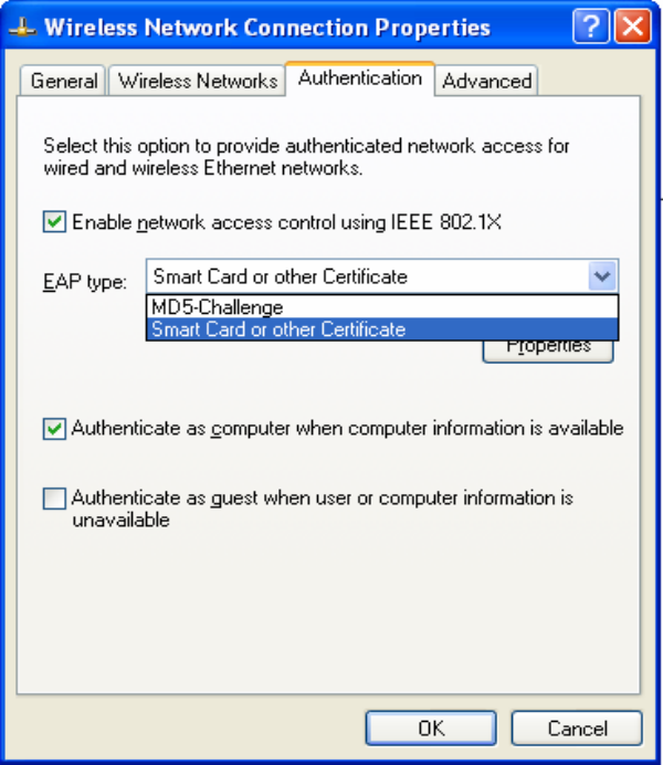
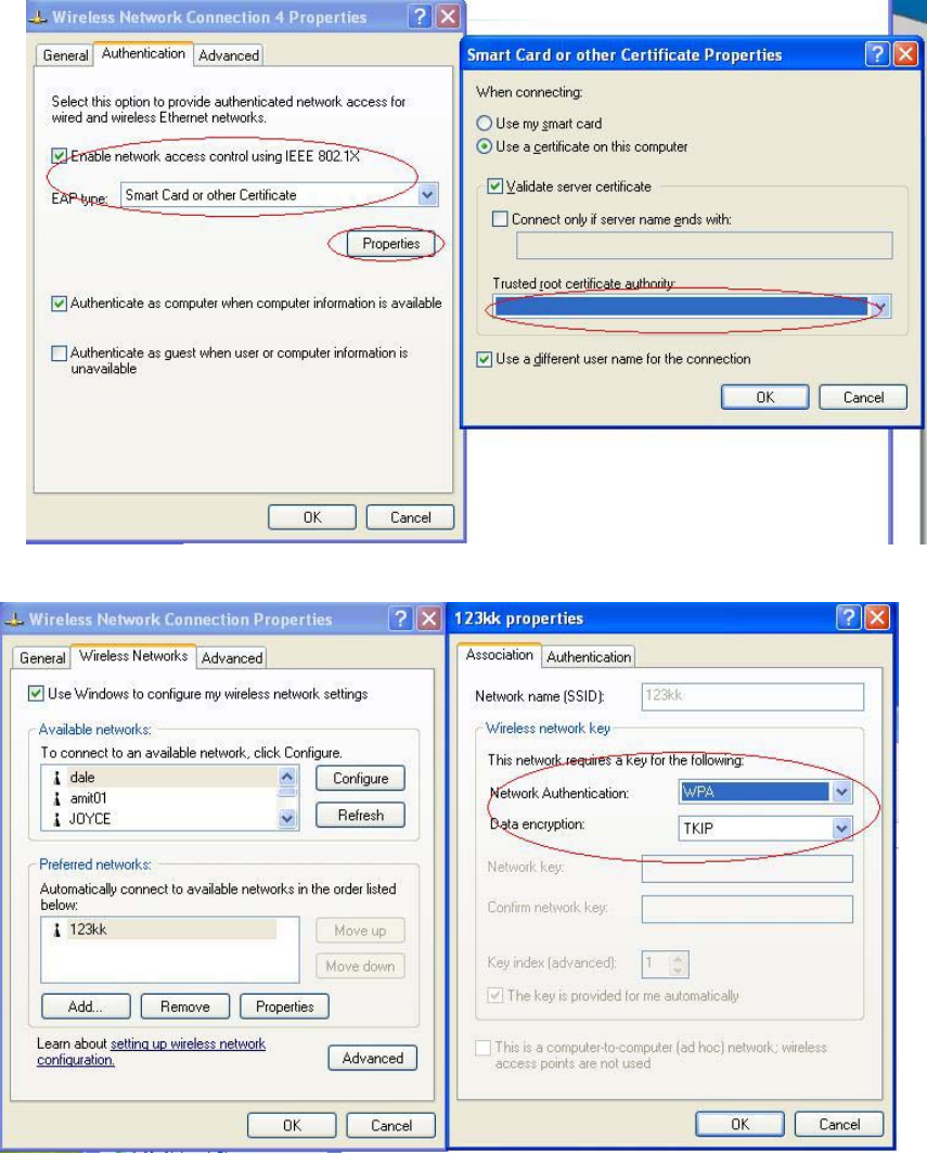
1.Choose the IEEE802.1X as the authentication method. (Fig 2)
Note.
Figure 2 is a setting picture of Windows XP without service pack 1. If users
upgrade to service pack 1, then they can’t see MD5-Challenge from EAP
type list any more, but they will get a new Protected EAP (PEAP) option.
2.Choose MD5-Challenge or Smart Card or other Certificate as the EAP
type.
3.If choosing use smart card or the certificate as the EAP type, we select to
use a certificate on this computer. (Fig 3)
85
4. We will change EAP type to fit the variable test condition.
Figure 2: Enable IEEE 802.1X access control
86
Figure 3: Smart card or certificate properties
4. Windows 2000 RADIUS server Authentication testing:
4.1DUT authenticate PC1 using certificate. (PC2 follows the same test procedures.)
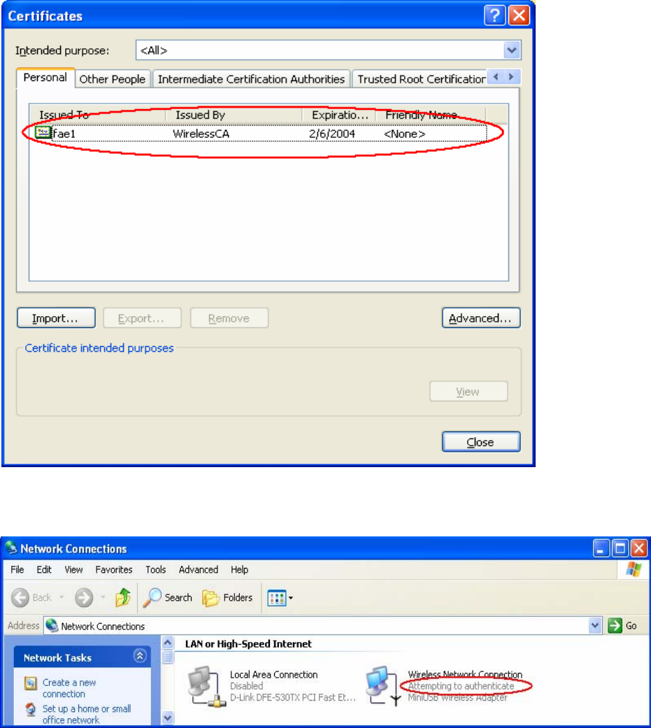
1. Download and install the certificate on PC1. (Fig 4)
2. PC1 choose the SSID of DUT as the Access Point.
3. Set authentication type of wireless client and RADIUS server both to
EAP_TLS.
4. Disable the wireless connection and enable again.
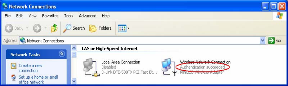
5. The DUT will send the user's certificate to the RADIUS server, and then
send the message of authentication result to PC1. (Fig 5)
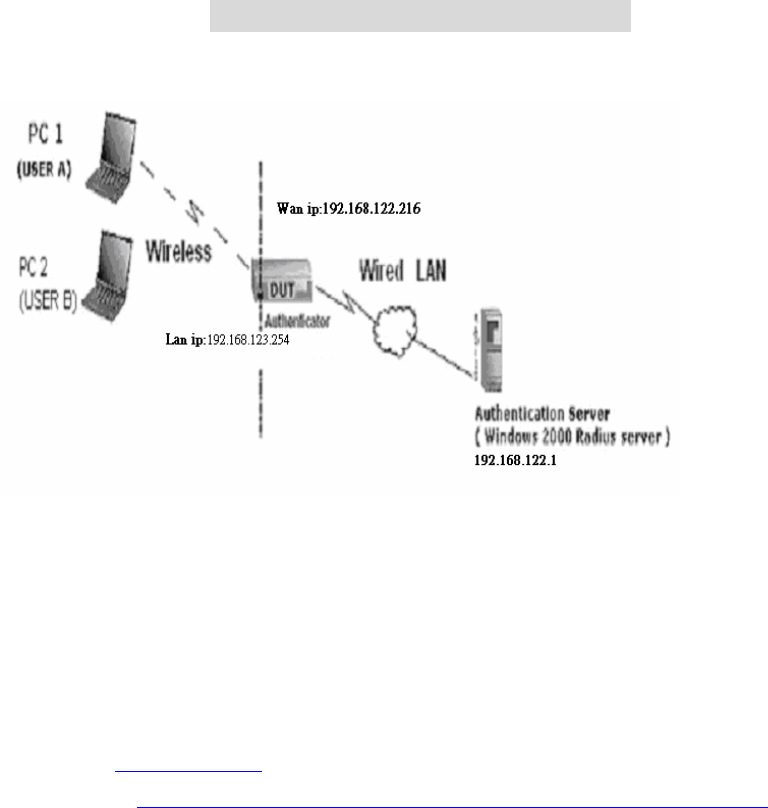
6. Windows XP will prompt that the authentication process is success or fail
and end the authentication procedure. ( Fig 6)
7. Terminate the test steps when PC1 get dynamic IP and PING remote host
successfully.
87
Figure 4: Certificate information on PC1
Figure 5: Authenticating
88
Figure 6: Authentication success
4.2DUT authenticate PC2 using PEAP-TLS.
1. PC2 choose the SSID of DUT as the Access Point.
2. Set authentication type of wireless client and RADIUS server both to
PEAP_TLS.
3. Disable the wireless connection and enable again.
4.The DUT will send the user's certificate to the RADIUS server, and then
send the message of authentication result to PC2.
5. Windows XP will prompt that the authentication process is success or fail
and end the authentication procedure.
6. Terminate the test steps when PC2 get dynamic IP and PING remote host
successfully.
Support Type: The router supports the types of 802.1x Authentication:
PEAP-CHAPv2 and PEAP-TLS.
Note.
1.PC1 is on Windows XP platform without Service Pack 1.
2.PC2 is on Windows XP platform with Service Pack 1a.
3.PEAP is supported on Windows XP with Service Pack 1 only.
4.Windows XP with Service Pack 1 allows 802.1x authentication only when data encryption
function is enable.
89
A
A
Ap
p
pp
p
pe
e
en
n
nd
d
di
i
ix
x
x
C
C
C
W
W
WP
P
PA
A
A-
-
-P
P
PS
S
SK
K
K
a
a
an
n
nd
d
d
W
W
WP
P
PA
A
A
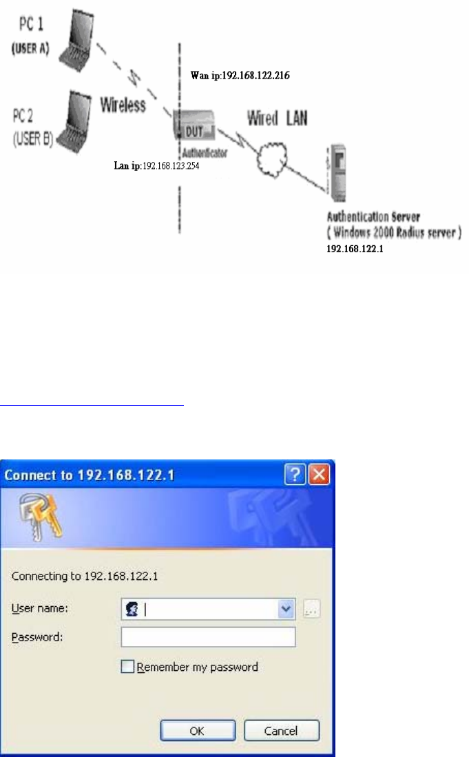
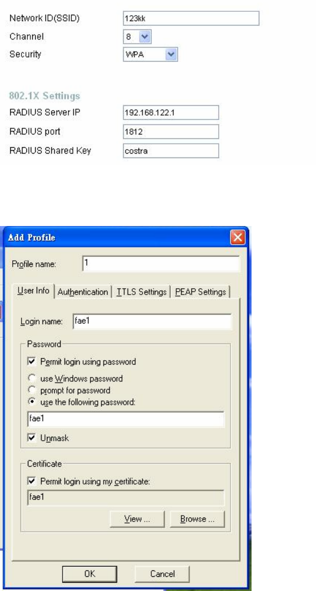
Wireless Router: LAN IP: 192.168.123.254
WAN IP: 192.168.122.216
Radius Server: 192.168.122.1
UserA : XP Wireless Card:Ti-11g
Tool: Odyssey Client Manager
Refer to: www.funk.com
Download: http://www.funk.com/News&Events/ody_c_wpa_preview_pn.asp
90
Or Another Configuration:
WPA-PSK
In fact, it is not necessary for this function to authenticate by Radius Server, the client
and wireless Router authenticate by themselves.
Method1:
1. Go to the Web manager of Wireless Router to configure, like below:
2. Go to Odyssey Client Manager, first choose “Network”
Before doing that, you should verify if the software can show the wireless card.
Open “Adapters”
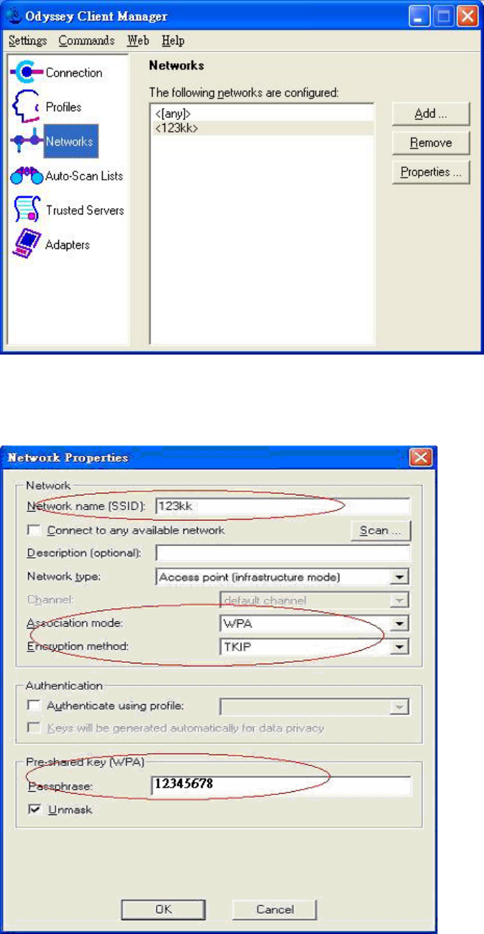
91
3. Add and edit some settings:
92
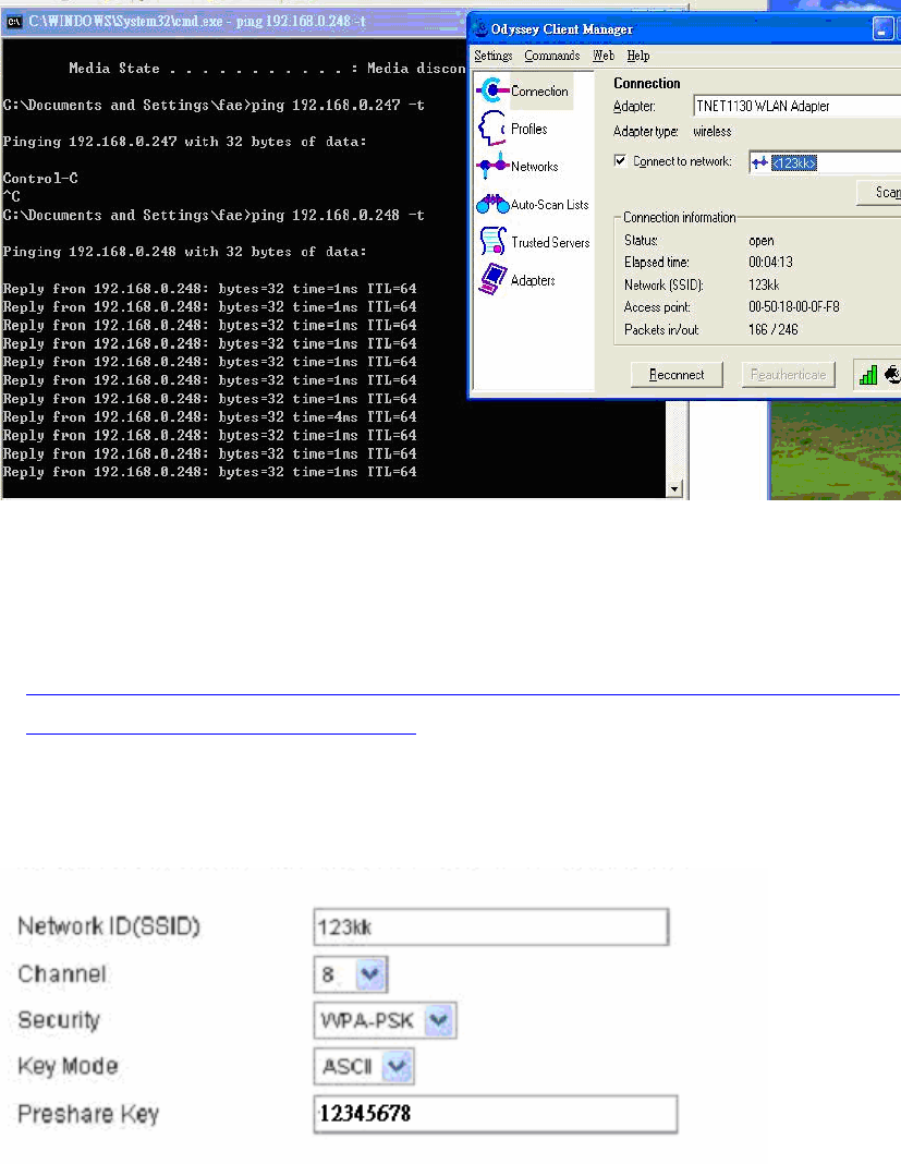
4. Back to Connection:
Then Select “Connect to network” You will see:
Method2:
1. First, patch windows XP and have to install “Service package 1”
Patch:
http://www.microsoft.com/downloads/details.aspx?displaylang=en&FamilyID=503
9ef4a-61e0-4c44-94f0-c25c9de0ace9
2. Then reboot.
3. Setting on the router and client:
Router:
Client:
Go to “Network Connection” and select wireless adapter.
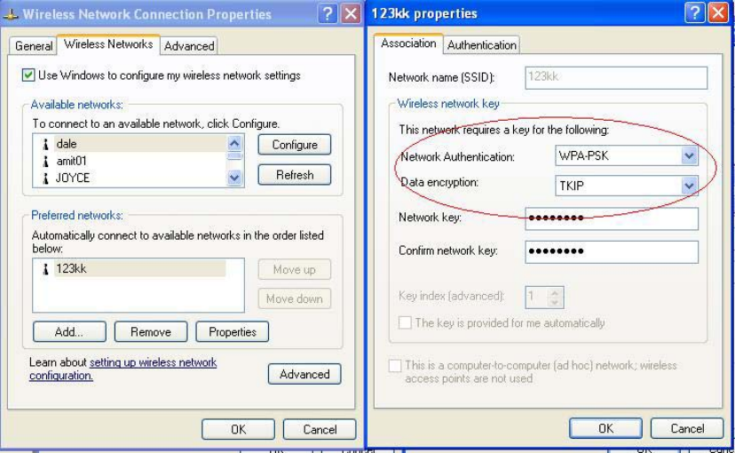
93
Choose “View available Wireless Networks” like below:
AdvancedÆ choose “123kk”
94
WPA:
For this function, we need the server to authenticate. This function is like 802.1x.
The above is our environment:
Method 1:
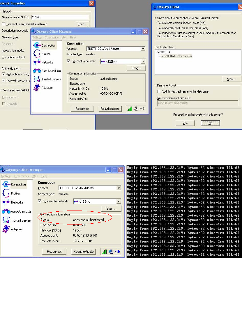
1. The UserA or UserB have to get certificate from Radius, first.
http://192.168.122.1/certsrv
account : fae1
passwd : fae1
2. Then, Install this certificate and finish.
3. Go to the Web manager of Wireless Router to configure, like below:
95
4. Go to Odyssey Client Manager, choose “Profiles” and Setup Profile name as “1”
Login name and passwd are fae1 and fae1.
Remember that you get certificate from Radius in Step1.
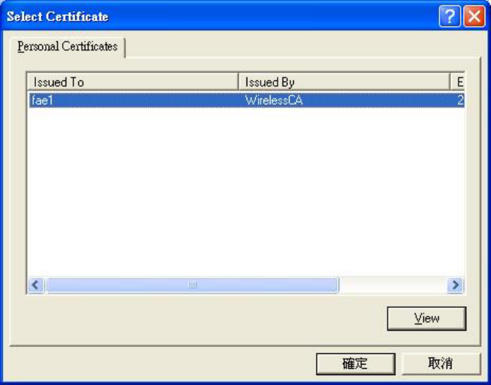
96
5. Then Choose “certificate” like above.
97
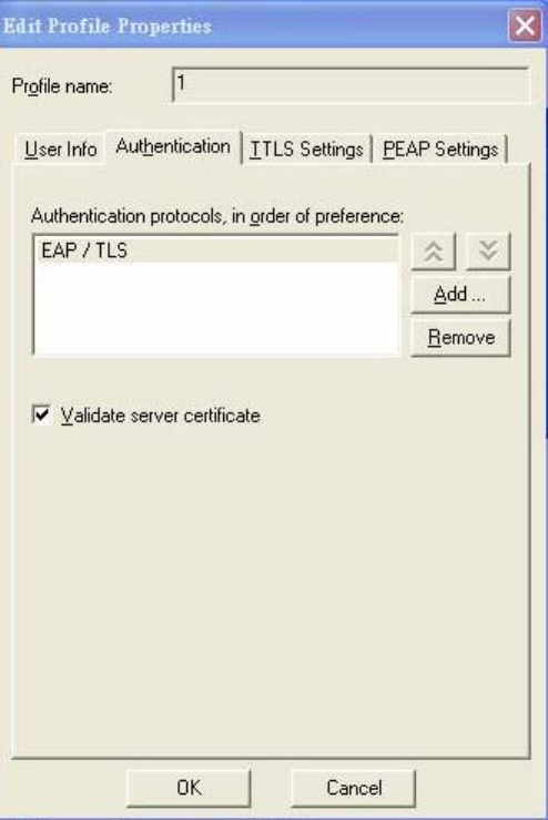
6. Then go to Authentication and first Remove EAP/ TLS and Add EAP/TLS again.
98
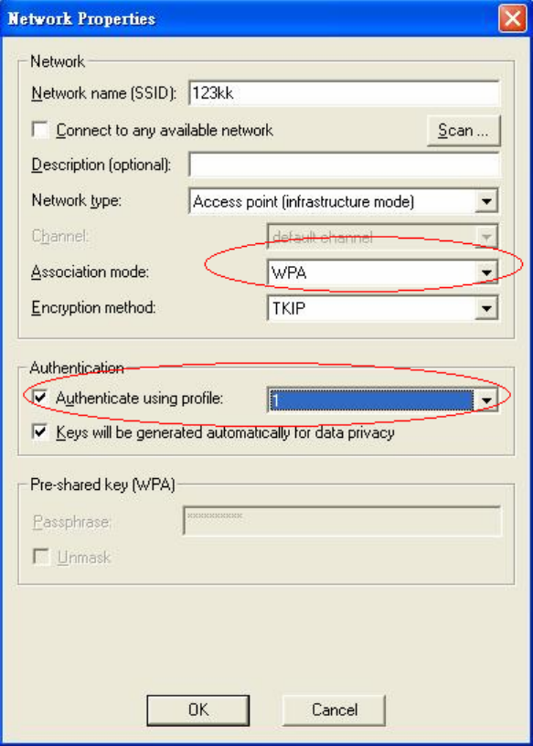
7. Go “Network” and Select “1” and ok
99
8. Back to Connection and Select “123kk.
If successfully, the wireless client has to authenticate with Radius Server, like below:
9.Result:
Method 2:
1. The UserA or UserB have to get certificate from Radius,first.
http://192.168.122.1/certsrv
account:fae1
passwd:fae1
100
2. Then Install this certificate and finish.
3. Setting on the router and client:
Router:
101
Client:
Go to “Network Connection” and select wireless adapter.
Choose “View available Wireless Networks” like below:
AdvancedÆ choose “123kk”
Select “WirelessCA and Enable” in Trusted root certificate authority:
Then, if the wireless client wants to associate, it has to request to authenticate.

102
A
A
Ap
p
pp
p
pe
e
en
n
nd
d
di
i
ix
x
x
D
D
D
F
F
FA
A
AQ
Q
Q
a
a
an
n
nd
d
d
T
T
Tr
r
ro
o
ou
u
ub
b
bl
l
le
e
es
s
sh
h
ho
o
oo
o
ot
t
ti
i
in
n
ng
g
g
Reset to factory Default
There are 2 methods to reset to default.
1. Restore with RESET button
First, turn off the router and press the RESET button in. And then, power on the router and push the RESET button
down until the M1 and or M2 LED (or Status LED) start flashing, then remove the finger. If LED flashes about 8
times, the RESTORE process is completed. However, if LED flashes 2 times, repeat.
2. Restore directly when the router power on
First, push the RESET button about 5 seconds (M1 will start flashing about 5 times), remove the finger
. The RESTORE process is completed.
FCC Channel selection disabled attestation:
The Channels 1-11 is just for USA used,other channels will be disabled by software.
the end user can not provide with any controls or software to allow operation outside
the USA frequency band for all future applications when selling this product in USA.
FCC Caution
1. The device complies with Part 15 of the FCC rules. Operation is subject to
the following two conditions:
(1)This device may not cause harmful interference.
(2)This device must accept any interference received, including interference
that may cause undesired operation.
2. FCC RF Radiation Exposure Statement: The equipment complies with
FCC RF radiation exposure limits set forth for an uncontrolled environment.
This equipment should be installed and operated with a minimum distance
of 20 centimeters between the radiator and your body.
3. This Transmitter must not be co-located or operating in conjunction with
any other antenna or transmitter.
4. Changes or modifications to this unit not expressly approved by the party
responsible for compliance could void the user authority to operate the
equipment.