Advance Security R42 Car Alarm Receiver User Manual 7920PINS qxp
Advance Security Inc Car Alarm Receiver 7920PINS qxp
Users Manual
Step 1: 10-Pin Main Harness Installation
The main wire harness contains 8 wires which all have a specific purpose.
Follow the wiring recommendations enclosed for each wire. Wires not used
should be released from the harness connector or taped off to prevent accidental
shorting.
Gray Wire: The gray wire is a pulsed ground output designed to activate the
vehicle’s existing car horn system in place of or in addition to a siren
sounding device. Connect the gray wire to the negative trigger wire on the
vehicle’s horn relay.
WARNING! Maximum output of this wire is 300mA. Horn systems requiring
positive voltage or more than 300mA to trigger the horn relay will require an
additional relay to increase current capabilities.
Blue Wire with White Stripe: This wire provides a single pulsed ground when
the 7921P is disarmed so that it will disarm a factory installed alarm system.
Note: Some factory alarms systems may require a double pulse signal to
disarm the factory alarm system. In this case, you will need to add Silencer
adapter model #5902DP to the blue wire with white stripe.
Brown Wire: The brown wire is the positive siren output wire. Connect the
brown wire from the harness to the brown wire on the siren supplied. Ground
the remaining black wire from the siren.
Blue Wire: The blue wire is a negative trigger input that can be used for existing
or newly installed grounding type hood/trunk/ hatch pin switches. The blue
wire can also be used as an input for additional ground output electronic
sensors.
Green Wire: The green wire is the negative (-) door trigger input. If the vehicle
you are working on has a negative (-) triggered dome light system, connect
the green wire to the common dome light trigger wire. This wire is usually
located at the driver’s side door jamb switch.
Violet Wire: The violet wire is the positive (+) door trigger input. If the vehicle
you are working on has a positive (+) triggered dome light system, connect
the violet wire to the common dome light trigger wire. This wire is usually
located at the driver’s side door jamb switch.
Red Wire with White Stripe: The red/white wire is the output of the parking light
relay. Connect the red/white wire to the parking light trigger wire coming from
the headlight switch. Do not connect the red/white wire to a dashboard
lighting wire. Connecting the red/white into dashboard lighting can damage
the dashboard lighting dimmer switch.
Pink Wire: The pink wire is the input wire to the parking light relay. The
connection of the pink wire determines the output polarity of the parking light
relay. If the parking light system you are connecting to is positive activation,
connect the pink wire to battery +12vdc. If the parking light system you are
connecting to is negative activation, connect the pink wire the the frame of
the vehicle.
Note: (Applies to All Models) The main 10 pin harness contains two vacant
sockets. These vacant sockets are for channel #2 output. All the alarm
modules require an 5912 for channel #2 operation. Follow the wiring
instructions supplied with 5912. If a 5912 relay is not available, a standard
Bosch 5 pin relay can be used.
Step 2: Arm / Disarm Harness Wiring (3-Pin White Socket)
Follow wiring diagram enclosed for proper connection to the factory installed
power door locking system to arm and disarm the 7921P security system.
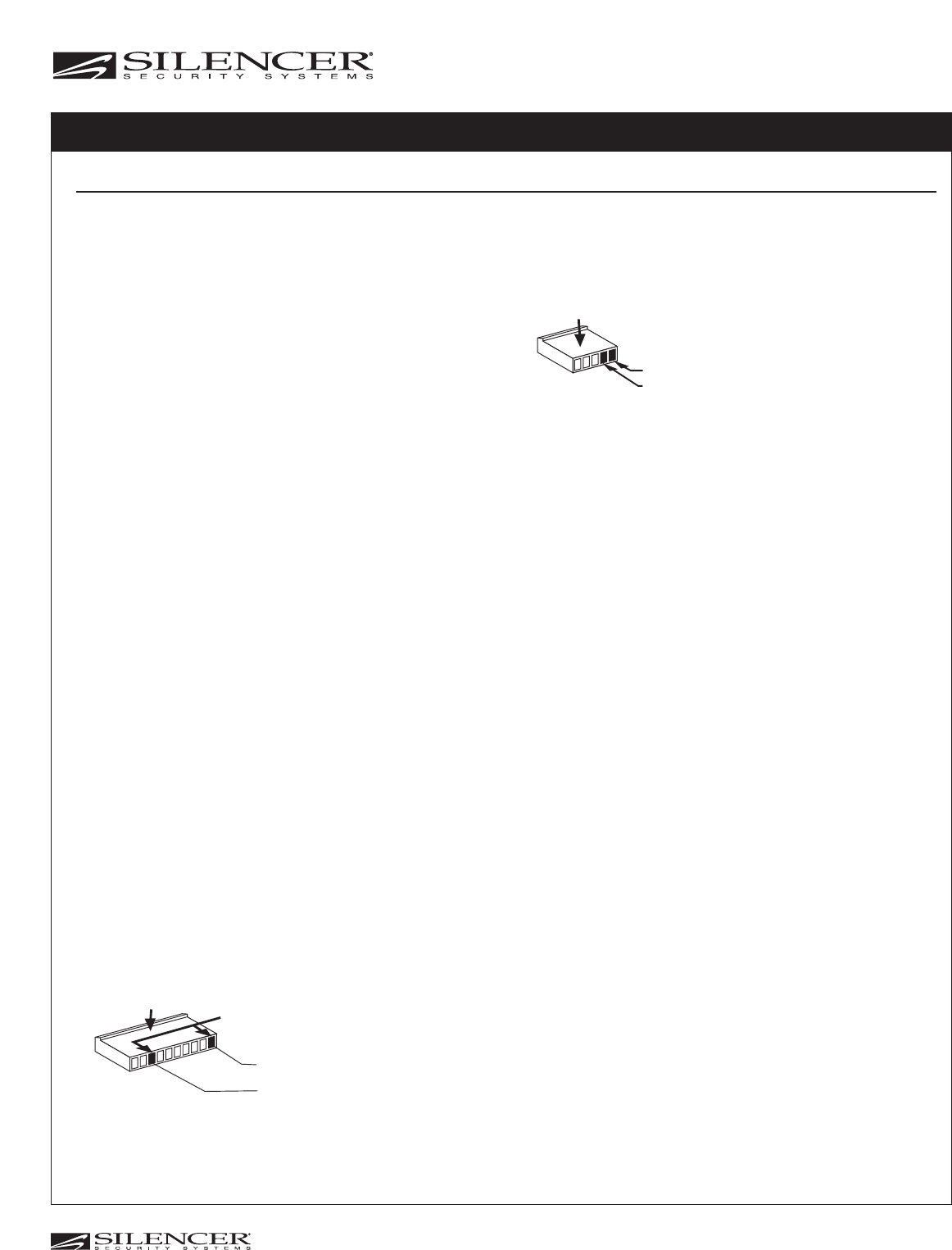
Step 3: 5-Pin Power Harness Installation
The power harness contains 3 wires and two vacant sockets, this power harness
does not come packaged with the alarm module but in 5901H1, 5901H2,
5901H3 harness kits or custom starter disable/power interface harnesses.
Packaged with the 10-pin main harness are two loose wires (an Orange wire and
a White wire with a Black stripe). Follow the wiring recommendations enclosed
for each wire.
Orange Wire: Insert the orange wire into the first socket of the power harness.
The orange wire is the dome light supervision control output. Connect the
orange wire to the required control relay.
White Wire with Black Stripe: Insert the white/black wire into the third socket of
the power harness. (As shown) The white/black wire is the (-) Channel #2
output wire and should be connected to an existing (-) activated trunk
release switch or an additional relay will have to be added to control the
trunk release mechanism.
Step 4:Door Lock/Unlock Socket (3- Pin Black Socket)
For remote controlled door lock/unlock operation, follow the wiring diagram
enclosed (page 2). The harness is an optional part not supplied with 7921P.
Order part # 5902 or 5903 for one-wire multiplexing door locking systems.
Step 5: Auxiliary Interrupt Wiring (2-Pin Orange Socket)
To interrupt an additional circuit(s), all alarm modules require either the ALA-
RPS, ALA-RPS2 or ALA-RPS3 relay pack. Follow the wiring instructions
supplied with the relay packs.
Step 6: Dip Switch Feature Programming
Dip Switch #1: Ignition Key Controlled Lock/Unlock (Door lock control function
must be connected and the door lock output feature must be “On” in the
dealer mode)
Note: This feature can be programmed using the #1 Dip Switch in both the
dealer and consumer modes.
Place Dip Switch #1 to the “On” position to activate this feature.
Place Dip Switch #1 in the “Off” position to deactivate this feature.
Dip Switch #2: Current Sensing
Note: This feature can be programmed using the #2 Dip Switch in both the
dealer and consumer modes.
Place Dip Switch #2 to the “On” position to have the current sensing feature on.
Place Dip Switch #2 in the “Off” position to have the current sensing feature off.
Dip Switch #3: Door Entry Delay
Note: This feature can be pre-programmed in dealer mode using the #3 Dip
Switch. The feature will not be functional in the dealer mode but will become
functional when the unit is converted to customer mode.
Place the dip switch in the "On" position. During customer mode operation,
the (+) or (-) door input trigger wires will have a 20 second entry delay. This
is primarily used for Ford vehicles that have keyless entry and use a door
mounted keypad.
Place the dip switch in the "Off" position (Factory Default) and the 20 second
door entry delay will be off (Instant Activation).
Step 7: Additional Menu Programming
The Silencer model 7921P control module offers additional menu programmable
features. Follow the dealer or consumer remote feature programming sheets to
adjust the 7921P features.
INSTALLATION INSTRUCTIONS
Model: 7921P
For Technical Assistance Call:
(800) 638-3600
Proposed
© 2005 Copyright Magnadyne Corp.
1111 West Victoria Street
Compton, CA 90220 www.magnadyne.com
Power Harness
First Socket (-) Domelight control output
Second Socket (+) 12 volts for the relay
Vacant Sockets
Main Harness
+12 Volts for Relay (when needed)
(-) Channel #2 Output
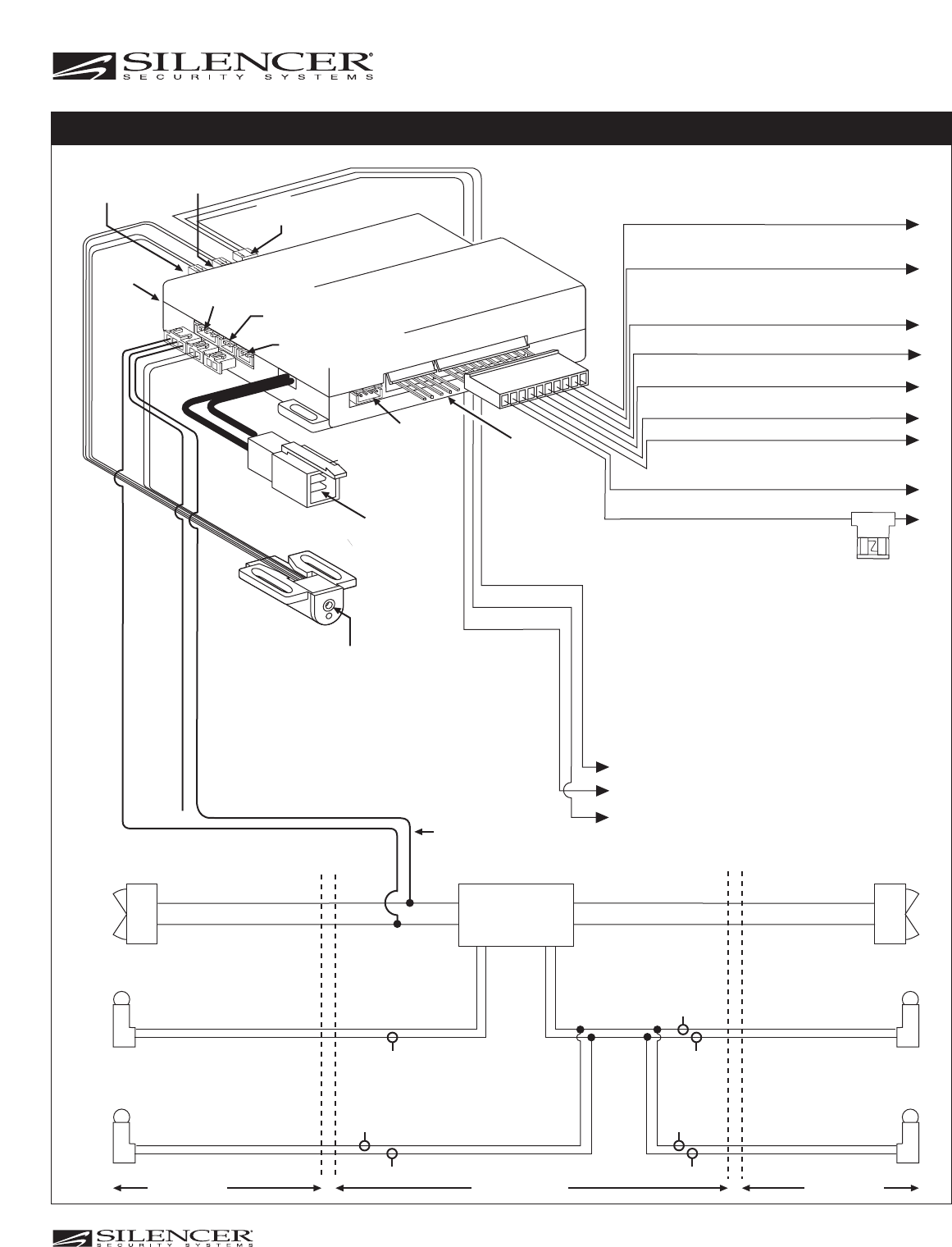
5-Pin Power
Harness*
7921P
Controller
Shock Sensor
(White 4-Pin Socket****)
Programmable Key Receptacle
for Changing to
Customer Mode
or
Putting Unit to Sleep Mode
* Supplied with 5901H1, 5901H2 or 5901H3 Harness Kits or
Custom Starter/Disable T-harness.
** Supplied with 5902 Ignition Controlled Locking Kit.
*** Supplied with ALA-RPS, ALA-RPS2 or ALA-RPS3 relay packs.
**** For a Single-Zone Shock Sensor use ALA930.
For a Dual-Zone Shock Sensor use ALA95 or ALA90.
***** This wire supplies +12V power, if not used cut this wire
off at connector to prevent shorting.
Pink Wire Parking Lights Relay Input
Red/White Wire Parking Lights Relay Output
Violet Wire Positive Door Trigger Input
White/Black Wire Channel #2 Output
Green Wire Negative Door Trigger Input
Blue Wire Negative Pin Trigger Input
Brown Wire
Positive (+) Output for
an Optional Electronic Siren
Blue/White Wire (-) Signal Output to
Disarm Factory Alarm
Gray Wire Horn (-) Pulsed Output
Starter Disable
Socket*
Driver's Door
Lock
Unlock
Factory Keyless
Module
(Typical)
Left Door
Lock/Unlock Switch
Lock
Unlock
Right Door
Lock/Unlock Switch
Left Door
Jamb
Right Door
Jamb
Lock (+)
Unlock (+)
Lock (+)
Unlock (+)
Right Front
Pass. Door
Left Rear
Pass. Door
Lock (+)
Unlock (+)
Right Rear
Pass. Door
Lock (+)
Unlock (+)
B
C
A
C
A
C
A
A = Possible Connection Points for Green Wire
B= Connection Point for Blue Wire
C = Possible Connection Points for White Wire
Inside Door Inside DoorInside Vehicle
Green Wire
White Wire
Blue Wire
Black Wire (Unlock)
Red Wire (Lock)
Orange Wire ***** 2nd Unlock Output (requires
additional relay & special wiring).
Optional
5902 Harness
Auxiliary Interrupt
(Orange 2-Pin Socket***)
Programmable Key
(Green 2-Pin Socket)
Ignition Locking**
(Black 3-Pin Socket)
LED
(White 2-Pin
Socket)
Valet Switch
(Blue 2-Pin Socket)
Arm/Disarm Harness
(White 3-Pin Socket)
DIP Switches
Proposed
© 2005 Copyright Magnadyne Corp.
INSTALLATION INSTRUCTIONS Model: 7921P
Models: 7921P, 7920P, 7919P Rev. C
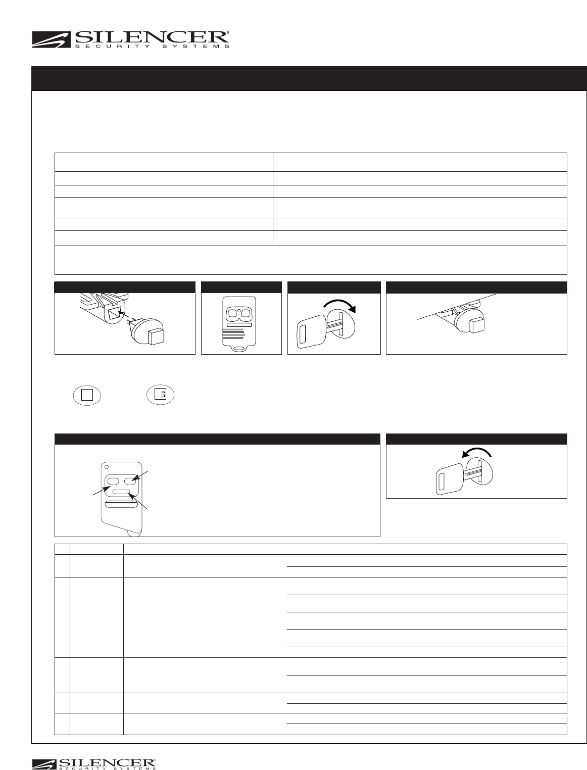
CONSUMER REMOTE FEATURE PROGRAMMING
OFF
Turn Off the Ignition
The horn/siren will emit 1 short chirp and 1 long chirp. You are
now out of the “Consumer Remote Feature Programming”
mode.
Step 6
NOTE: The alarm must be in “consumer mode” before you can program
consumer mode features. See additional instruction sheets on performing this
function. When the
alarm
is programmed to consumer mode, a specific group of
operating features are reset to their default settings. These default settings can be
changed by following the enclosed procedures and using the special 7910P
programming transmitter.
NOTE: In the event that the 7910P transmitter is unavailable, the programming
can also be performed by the consumer transmitter once all buttons have been
programmed into the control module memory. (See “Consumer Remote Feature
Programming from the Consumer's Transmitter.) To get into the “Consumer
Remote Feature Programming” mode follow the procedures below”.
#Programmable Alarm Feature Default Setting
(Consumer Transmitter Mode) (Consumer Transmitter Mode)
1
Chirp Status Indicator Chirps On
2A *Mode “P” Automatic Arming of Alarm “On”, Automatic Arming of Starter Disable “On”
2B *Mode “S” Automatic Arming of Alarm “Off”, Automatic Arming of Starter Disable “On”
Starter Disable will Arm 70 Seconds After Last Door is Closed
3 Remote Panic from Factory Keyless Entry Transmitter On
4 Safety Illumination Sentinel System Off
# Button Color Function Confirmation = Change Function
1
Black Chirp Status Indication 1 Beep = Chirp Status Indication “On”
2 Beeps = Chirp Status Indication “Off”
2A Blue Mode “P”
1 Beep = Automatic Arming of Alarm “On”, Automatic Arming of Starter Disable “On”
Both will arm 10 seconds after last door is closed or rearm 10 seconds after remote disarm.
2 Beeps = Automatic Arming of Alarm “On”, Automatic Arming of Starter Disable “On”
Both will arm 20 seconds after last door is closed or rearm 20 seconds after remote disarm.
3 Beeps = Automatic Arming of Alarm “On”, Automatic Arming of Starter Disable “On”
Both will arm 45 seconds after last door is closed or rearm 60 seconds after remote disarm.
4 Beeps = Automatic Arming of Alarm “Off”, Automatic Arming of Starter Disable “On”
The starter will disable 70 seconds after last door is closed.
5 Beeps = Automatic Arming of Alarm “Off”, Automatic Arming of Starter Disable “Off”
2B
Blue
Mode “S” 1 Beep = Automatic Arming of Alarm “On”, Automatic Arming of Starter Disable “On”
Both will arm 45 seconds after last door is closed.
2 Beeps = Automatic Arming of Alarm “Off”, Automatic Arming of Starter Disable “On”
The starter will disable 70 seconds after last door is closed.
3
Red
Remote Panic from Factory Keyless
1 Beep = Panic “On”
Entry Transmitter
2 Beeps = Panic “Off”
4
Black + Blue Safety Illumination Sentinel System 3 Beeps = Safety Illumination Sentinel System “On”
4 Beeps = Safety Illumination Sentinel System “Off
Black
Button
Blue
Button
Red
Button
Use the 5910P transmitter and the chart below to
change the features as required. Press and hold
the button that controls the function you want to
change and listen for the chirp confirmation. You
can repeatedly press the same colored button
and turn the same function on and off as many
times as required until the operation is correct.
After all functions have been re-programmed to
operate as required go to step 6.
5910P Programming Transmitter
Step 5
Step 2
☛
ON
☛
Disarm Security
System
The LED will be off and
the horn/siren will emit 2
chirps.
Insert the Valet Switch Turn On Ignition
The LED will remain off.
Push the Valet Switch:
6 Times if Using a Red Button Switch
12 Times if Using a Black Button Switch
(Represents 6 Times On/Off)
The LED will be on solid and the horn/siren will emit 1 long
then 1 short chirp. You are now in the “Consumer Remote
Feature Programming” mode.
Step 1 Step 3 Step 4
ON
OFF
Dealer Switch
(Red Button)
Consumer Switch
(Black Button)
Momentary Switch
Push On/Off Toggle Switch
Push Once = On
Push Again = Off
* During Dealer Remote Feature Programming either the ”P” or “S” mode was selected. In the Consumer Remote Feature Programming mode you cannot change the mode (either
“S” or “P”) that was selected in the Dealer Feature Programming. You can change the features of the mode that was selected in the Dealer Mode. (See Step 5 for more details.) To
change mode “S” or “P” operation you have to recode a dealer transmitter to the unit and change the operation in the “Dealer Remote Programmable Feature” Mode.
Note: The auto arm door locking feature has
a default setting of "off" in customer mode.
To turn on or off the auto arm door locking
feature in customer mode, repeat the steps
for the "Blue" button and hold the transmitter
button down for more than 3 seconds to get
a second confirmation chirp. For example: (1
chirp = 10 sec auto arm on, auto door lock
off.) (1 chirp + 1 chirp = 10 sec auto arm on,
auto door lock on.)
Proposed
© 2005 Copyright Magnadyne Corp.
1111 West Victoria Street
Compton, CA 90220 www.magnadyne.com
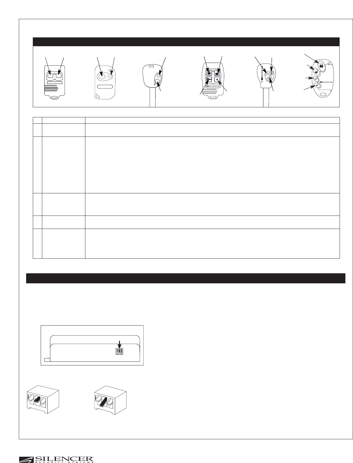
AUXARM/DIS AUXARM/DIS AUX
ARM/DIS
AUX
PANIC
LOCK UNLOCK
# Button Function Confirmation = Change Function
1
ARM/DIS or LOCK Chirp Status Indication and Single/ 1 Beep = Chirp Status Indication “On”
Dual Unlock Outputs 2 Beeps = Chirp Status Indication “ Off”
2A AUX (2-Button) or Mode “P”
1 Beep = Automatic Arming of Alarm “On”, Automatic Arming of Starter Disable “On”
TRUNK (3-Button) or Both will arm 10 seconds after last door is closed or rearm 10 seconds after remote disarm.
UNLOCK
2 Beeps = Automatic Arming of Alarm “On”, Automatic Arming of Starter Disable “On”
Both will arm 20 seconds after last door is closed or rearm 20 seconds after remote disarm.
3 Beeps = Automatic Arming of Alarm “On”, Automatic Arming of Starter Disable “On”
Both will arm 45 seconds after last door is closed or rearm 60 seconds after remote disarm.
4 Beeps = Automatic Arming of Alarm “Off”, Automatic Arming of Starter Disable “On”
The starter will disable 70 seconds after last door is closed.
5 Beeps = Automatic Arming of Alarm “Off”, Automatic Arming of Starter Disable “Off”
2B
AUX (2-Button) or
Mode “S” 1 Beep = Automatic Arming of Alarm “On”, Automatic Arming of Starter Disable “On”
UNLOCK Both will arm 30 seconds after last door is closed.
2 Beeps = Automatic Arming of Alarm “Off”, Automatic Arming of Starter Disable “On”
The starter will disable 70 seconds after last door is closed.
3
Red Button on
Remote Panic from Factory Keyless
1 Beep = Panic “On”
5910P Only Keyless Transmitter 2 Beeps = Panic “Off”
4
ARM/DIS (2-Button)+ Safety Illumination Sentinel System 3 Beeps = Safety Illumination Sentinel System “On”
AUX (2 Button) or 4 Beeps = Safety Illumination Sentinel System “Off”
LOCK + UNLOCK
AUX
UNLOCK
LOCK
PANIC
LOCK
UNLOCK
AUX
Note: The auto arm door locking feature has
a default setting of "off" in customer mode.
To turn on or off the auto arm door locking
feature in customer mode, repeat the steps
for the "Blue" button and hold the transmitter
button down for more than 3 seconds to get
a second confirmation chirp. For example: (1
chirp = 10 sec auto arm on, auto door lock
off.) (1 chirp + 1 chirp = 10 sec auto arm on,
auto door lock on.)
REMOTE FEATURE PROGRAMMING USING THE CONSUMER’S TRANSMITTER
Consumer Remote Feature Programming (7921P, 7920P, 7919P Rev. C)
FEATURE PROGRAMMING USING THE CONTROL MODULE’S DIP SWITCHES
The Silencer®model 7921P control module offers 3
programmable features. Follow the instructions enclosed to
program these features using the Dip switches in the control
module.
O
N12 3
O
N12 3
#2 Dip
Switch in the
“Off”
Position
#2 Dip
Switch in the
“On”
Position
Difference Between if a Dip Switch in Off or On
Dip Switch #1: Ignition Key Controlled Lock/Unlock (Door lock control function
must be connected and the door lock output feature must be “on” in the
dealer
mode)
Note: This feature can be programmed using the #1 Dip switch in both the
dealer and consumer modes.
Place Dip switch #1 to the “On” position to activate this feature.
Place Dip switch #1 in the “Off” position to deactivate this feature.
Dip Switch #2: Current Sensing
Note: This feature can be programmed using the #2 Dip switch in both the
dealer and consumer modes.
Place Dip switch #2 to the “On” position to have the current sensing feature on.
P
lace Dip switch #2 in the “Off” position to have the current sensing feature off
.
Dip Switch #3: Door Entry Delay (Applies to 7921P only)
Note: This feature can be pre-programmed in dealer mode using the #3 dip
switch. The feature will not be functional in the dealer mode but will become
functional when the unit is converted to customer mode.
Place Dip switch #3 in the "on" position. During customer mode operation, the
(+) or (-) door input trigger wires will have a 20 second entry delay. This is
primarily used for Ford vehicles that have keyless entry and use a door
mounted keypad.
Place Dip switch #3 in the "off" position (Factory default) and the 20 second
door entry delay will be off (Instant Activation).
Back View of Housing
Dip Switches
ON
Proposed
© 2005 Copyright Magnadyne Corp.
1111 West Victoria Street
Compton, CA 90220 www.magnadyne.com
Proposed
© 2005 Copyright Magnadyne Corp.
1111 West Victoria Street
Compton, CA 90220 www.magnadyne.com
Models: 7921P, 7920P, 7919P Rev. C
Step 2
ON
☛
Disarm Security
System
The LED will be off and
the horn/ siren will emit 2
short beeps.
Insert the Valet Switch Turn On Ignition Push the Valet Switch:
4 Times if Using a Red Button Switch
8 Times if Using a Black Button Switch
(Represents 4 Times On/Off)
The LED will be on solid. The horn/ siren will emit 1 long
then 1 short beep) You are now in the “Dealer Remote
Feature Programming” mode.
Step 1 Step 3 Step 4
Step 5
Momentary Switch
Push On/Off
Toggle Switch
Push it On then
Push it again for Off
ON
OFF
Dealer Switch
(Red Button) Consumer Switch
(Black Button)
OFF
Turn Off the Ignition
The LED will be off and the
horn/siren will emit 1 short
beep and 1 long beep. You are
now out of the feature
programming mode.
Step 6
When the Silencer®security system control module learns the
dealer transmitter operating code, a specific group of features
are automatically programmed to their default settings.
Enclosed, is a chart of the default settings for dealer transmitter
operation.
These default setting can only be changed by following the
enclosed procedures and using the special 5910P programming
transmitter (Shown Below).
To get into the “Dealer Remote Feature Programming” mode
repeat the following procedures:
#Programmable Feature Default Setting
1 Single/Dual Unlock Pulses Single
2 Automatic Arm Door Locking (See Note 1) On
3 Chirp Status Indicator (See Note 2) On
4 Consumer Remote Feature Programming Modes for Automatic Mode “P”
Arming of Alarm and Automatic Arming of Starter Disable.
( See Step 5 and Note 3 for Full Details)
Note: Pre-programming the “P and S” type auto arming modes is for use when the system is
put into consumer mode only. In dealer mode, auto arming is on without On/Off programming
and auto arm locking is on but can be programmed off as explained below.
# Button Color Changed Function Confirmation
1Black Single or Dual Unlock Outputs 1 Beep = Single Unlock Pulse
2 Beeps = Dual Unlock Pulses
2Blue Dealer Mode Auto Arm Door Locking 1 Beep = Automatic Arm Door Locking On, Consumer Auto Arm is ON
Pre-Programmed Consumer Mode Auto Arm 2 Beeps = Automatic Arm Door Locking OFF, Consumer Auto Arm is ON
3 Beeps = Automatic Arm Door Locking On, Consumer Auto Arm is OFF
4 Beeps = Automatic Arm Door Locking OFF, Consumer Auto Arm is OFF
3Red Chirp Status Indicator On/Off 1 Beep = On, 2 Beeps = Off
4**Black + Blue Selects “P” or “S” Mode Operation 4 Beeps = Mode “P” (See 2A Consumer Programming)
Automatic Arming of Alarm is “Programmable”
and Automatic Arming of Starter Disable is
“Programmable” in Consumer Mode Only.
3 Beeps = Mode “S” (See 2B Consumer Programming)
Automatic Arming of Alarm is “Programmable”
in Consumer Mode. Automatic Arming of
Starter Disable is Always “On” and is
“Not Programmable” in Dealer or Consumer Mode.
Black
Button Blue
Button
Red
Button
Use the 5910P transmitter and the chart below to adjust the features as
required. Press the button that controls the function you want to change and
listen for the chirp confirmation. You can repeatedly press the same colored
button and turn the same function on and off as many times as required until the
operation is correct. After all functions have been re-programmed to operate as
required go to step 6.
5910P Programming Transmitter
DEALER REMOTE FEATURE PROGRAMMING
☛
*
Note 2: When transmitter operation
is changed from a dealer
transmitter to a consumer
transmitter the horn/siren
and chirp indicator will return
to an “on” condition.
Note 1: When transmitter operation is changed from a
dealer transmitter to a consumer transmitter the
automatic arm locking feature will default to
“OFF”. This feature can be programmed on in the
customer mode by following the consumer feature
programming chart.
Note 3: When transmitter operation is changed from a
dealer transmitter to a consumer transmitter, the
automatic arming of alarm and automatic arming
of starter disable (Mode “S” or “P”) will remain as
programmed in the dealer transmitter mode. In
order to change Mode “S” or Mode “P” operation,
you have to re-code a dealer transmitter to the
unit and change the operation in the dealer
remote programmable feature mode.
** Note: The Black +Blue Buttons Change Automatic Alarm
Arming of Alarm and Automatic Arming of Starter Disable in
the Consumer Mode Only!
Default Dealer Mode Operation is Always: Automatic Arming of
Alarm “On”, Automatic Arming of Starter Disable “On” and
Automatic Door Locking “On”.
Proposed
© 2005 Copyright Magnadyne Corp.
1111 West Victoria Street
Compton, CA 90220 www.magnadyne.com
Models: 7921P, 7909P, 7905P
6900P, 6900P-2, 6905P, 6909P
ON O
Turn On Ignition Insert a Dealer or
Customer Key
A. Horn chirps once to indicates the
code has been learned.
B. LED starts flashing slowly to
indicate the code has been
learned.
OR
Step 2
Insert the Valet Switch
Step 1
Dealer Switch
(Red Button)
Consumer Switch
(Black Button)
☛
Push the Valet Switch
3 Times for Red Button
6 Times for Black Button
(Represents 3 Times On/Off)
A. Long horn chirp indicates the unit
is in code learning mode.
B. LED comes on indicating the unit is
in code learning mode.
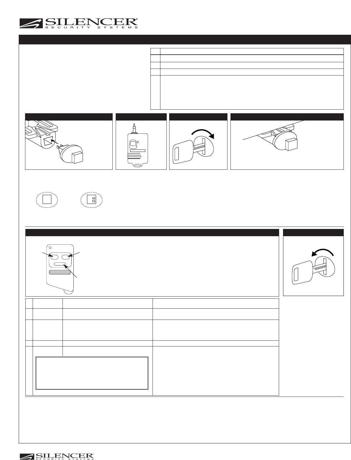
WAKING UP A UNIT FROM THE “SLEEP MODE”
ON
OFF
Momentary Switch
(Push On/Off) Toggle Switch
(Push On then
push it again for off)
Step 3
Remove the Dealer or
Customer Key
Step 5
OR
Turn Off Ignition
A. Horn chirps 1 short then 1 long to
indicates you have exited code
learning.
B. LED starts flashing slowly.
Step 6
OFF
☛
Step 4
Proposed
© 2005 Copyright Magnadyne Corp.
1111 West Victoria Street
Compton, CA 90220 www.magnadyne.com
ON O
OFF
☛
Turn On Ignition Push the Valet Switch
6 Times for Red Button
12 Times for Black Button
(Represents 6 Times On/Off)
A. The LED will flash 6 times.
B. 6900P, 6900P-2 or 6905P: If the
5911 buzzer is installed, it will emit
6 beeps.
6909P: The horn/siren will emit 6
beeps. Also the parking lights will
flash 6 times.
Turn Off Ignition
A. The LED will be off. You are now
in the “Sleep” mode.
☛
Step 2
Insert the Valet Switch
Step 1
Dealer Switch
(Red Button)
Consumer Switch
(Black Button)
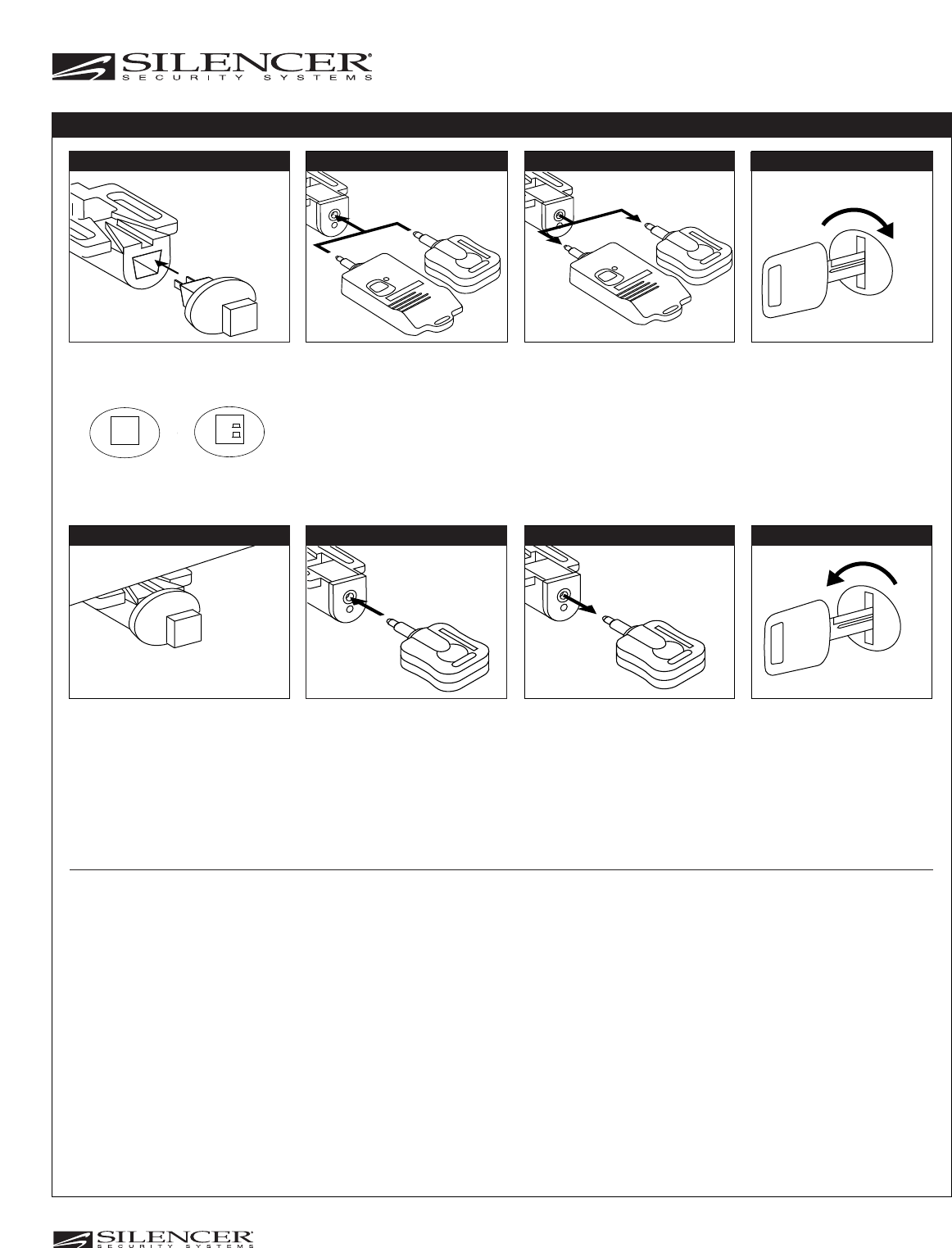
Insert the White “Sleep”
Key into the Receptacle
In the event the customer declines to purchase the Silencer security system and the system is not going to be removed
from the vehicle, it must be put into “Sleep” mode to prevent automatic arming.
The white sleep key can also be used to delete a dealer code and to reset the security system to it’s original state as it
was received from the factory.
Note: The system must be in dealer mode to use the white key. If the system is armed, you should disarm it with the
dealer key to prevent triggering.
Step 6
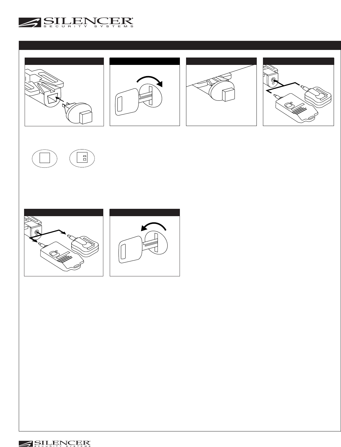
PROGRAMMING THE UNIT TO “SLEEP MODE”
ON
OFF
Momentary Switch
(Push On/Off) Toggle Switch
(Push On then
push it again for off)
Step 3
Remove the White “Sleep”
Key
Step 5
Step 4
Models: 7921P, 7909P, 7905P
6900P, 6900P-2, 6905P, 6909P
Proposed
© 2005 Copyright Magnadyne Corp.
1111 West Victoria Street
Compton, CA 90220 www.magnadyne.com
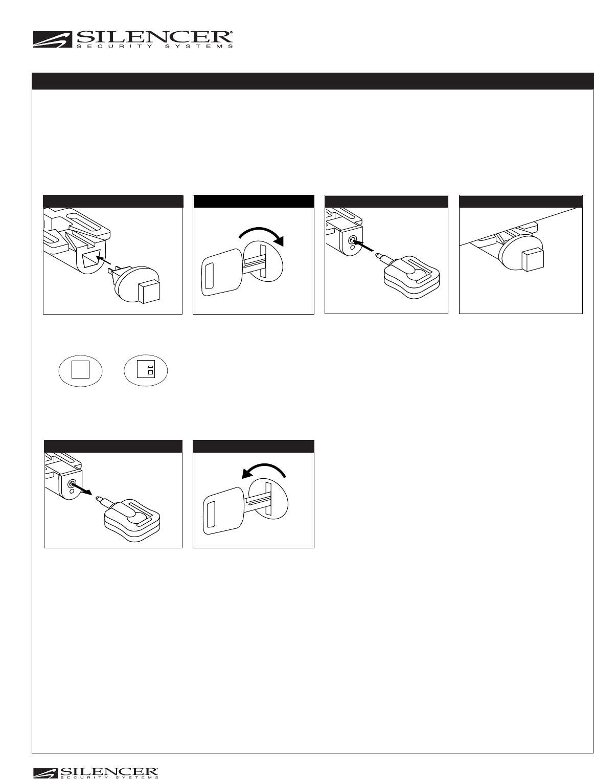
Models: 7921P, 7909P, 7905P
6900P, 6900P-2, 6905P, 6909P
ON O
OFF
☛
Turn On Ignition
Push the Valet Switch
6 Times for Red Button
12 Times for Black Button
(Represents 6 Times On/Off)
A. The LED will flash 6 times. (6905P
and 6909P)
B. 6905P: If the 5911 buzzer is
installed, it will emit 6 beeps.
6909P: The horn/siren will emit 6
beeps. Also the parking lights will
flash 6 times.
Turn Off Ignition
A. The LED will be off. (6905P and
6909P) You have now deleted all
key codes.
B. The horn/siren/chirper will emit 1
short and 1 long chirp.
Note: When dealer or consumer key
code is deleted the security system
will be in the consumer mode..
☛
Step 3
Insert the Valet Switch
Step 2
Dealer Switch
(Red Button)
Consumer Switch
(Black Button)
Insert the Orange
“Delete Code” Key into
the Receptacle
Upon the customer purchasing the 6905P or 6909P, it will arm/disarm from the factory keyless remotes. He/she also
has the option of purchasing a customer key pack (5900PKP) to disarm the security system.
In the event the customer declines to purchase the customer Key Pack (5900PKP) the dealer key code “must” be
deleted. This is done by programming in the bright orange “dealer delete key”.
If the customer declines to purchase the customer key pack for the 6909P, but still wants the unit to automatically arm;
see 6909P Feature Programming to activate this feature.
Step 7
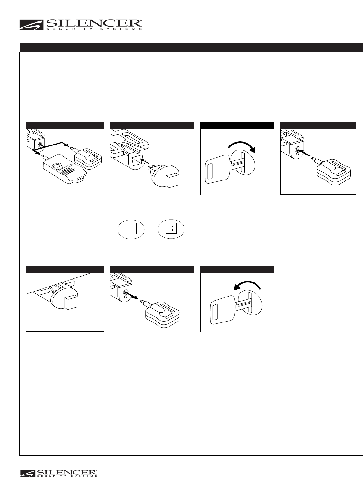
DELETING THE DEALER OR CONSUMER KEY
ON
OFF
Momentary Switch
(Push on/off) Toggle Switch
(Push on then
push it again for off)
Step 4
Remove the Orange “Delete
Code” Key
Step 6Step 5
OR
Disarm the Security
System
Step 1
ON O
OR
OFF
☛
OR
Remove the Dealer Key Turn On Ignition
Insert the Customer Key
A. Another short horn chirp indicates
the key code was learned.
Note: The system will automatically
exit code learning if a key is not
inserted within 15 seconds.
*** Model: 5900PKP
Turn Off Ignition
A. A short and long horn chirp
indicates you have exited code
learning.
Remove the Customer Key
Step 3 Step 4
Step 6 Step 8
Step 7
Insert the Dealer Key
Step 2
Insert the Valet Switch
Step 1
Dealer Switch
(Red Button)
Consumer Switch
(Black Button)
☛
Push the Valet Switch
3 Times for Red Button
6 Times for Black Button
(Represents 3 Times On/Off)
A. Long horn chirp indicates the unit is in
code learning mode.
Step 5
Note: The dealer key will be erased when programmed to the customer key.
CONSUMER KEY CODING
ON
OFF
Momentary Switch
(Push On/Off) Toggle Switch
(Push On then
push it again for off)
**
*
* Model: 5910K
** Model: 5900-DB (Blue Key)
5900-DG (Green Key)
5900-DR (Red Key)
5900-DY (Yellow Key)
***
Models: 7921P, 7909P, 7905P
6900P, 6900P-2, 6905P, 6909P
Proposed
© 2005 Copyright Magnadyne Corp.
1111 West Victoria Street
Compton, CA 90220 www.magnadyne.com
This device complies with part 15 of the FCC rules. Operation is subject to the following two conditions.
1)•This device may not cause harmful interference, and
2)•This device must accept any interference received, including interference that may cause undesired operation.
Per FCC 15.21, you are cautioned that changes or modifications not expressly approved by the part responsible for compliance
could void the user’s authority to operate the equipment.