Advance Security TR13 Car Alarm Transceiver User Manual MODEL 6876
Advance Security Inc Car Alarm Transceiver MODEL 6876
UserManual.wiki
>
Advance Security
>
TR13 User Manual
Users Manual
Navigation menu
Upload a User Manual
Namespaces
Wiki Guide
HTML
PDF
Info
Views
User Manual
Discussion / Help
Navigation
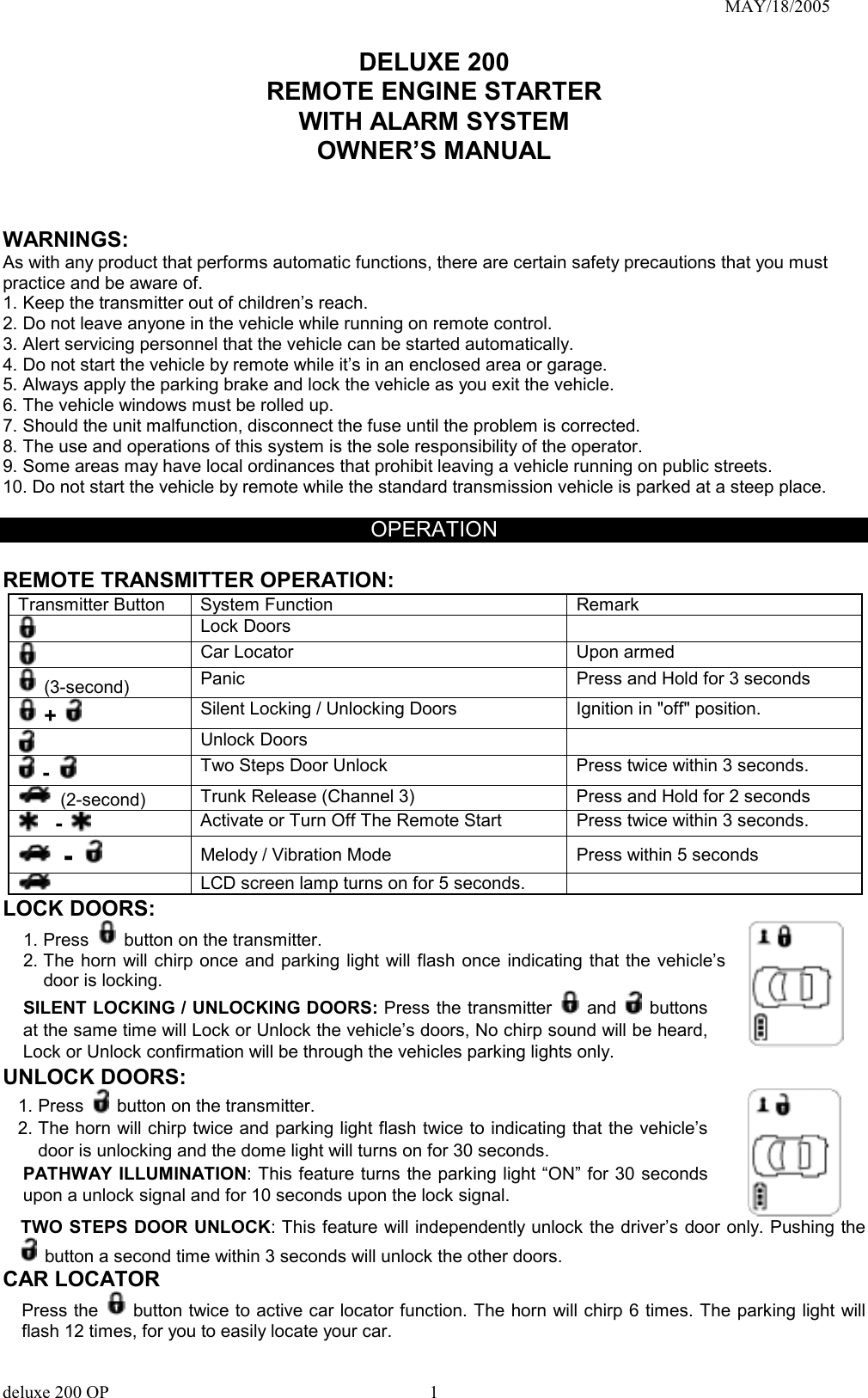
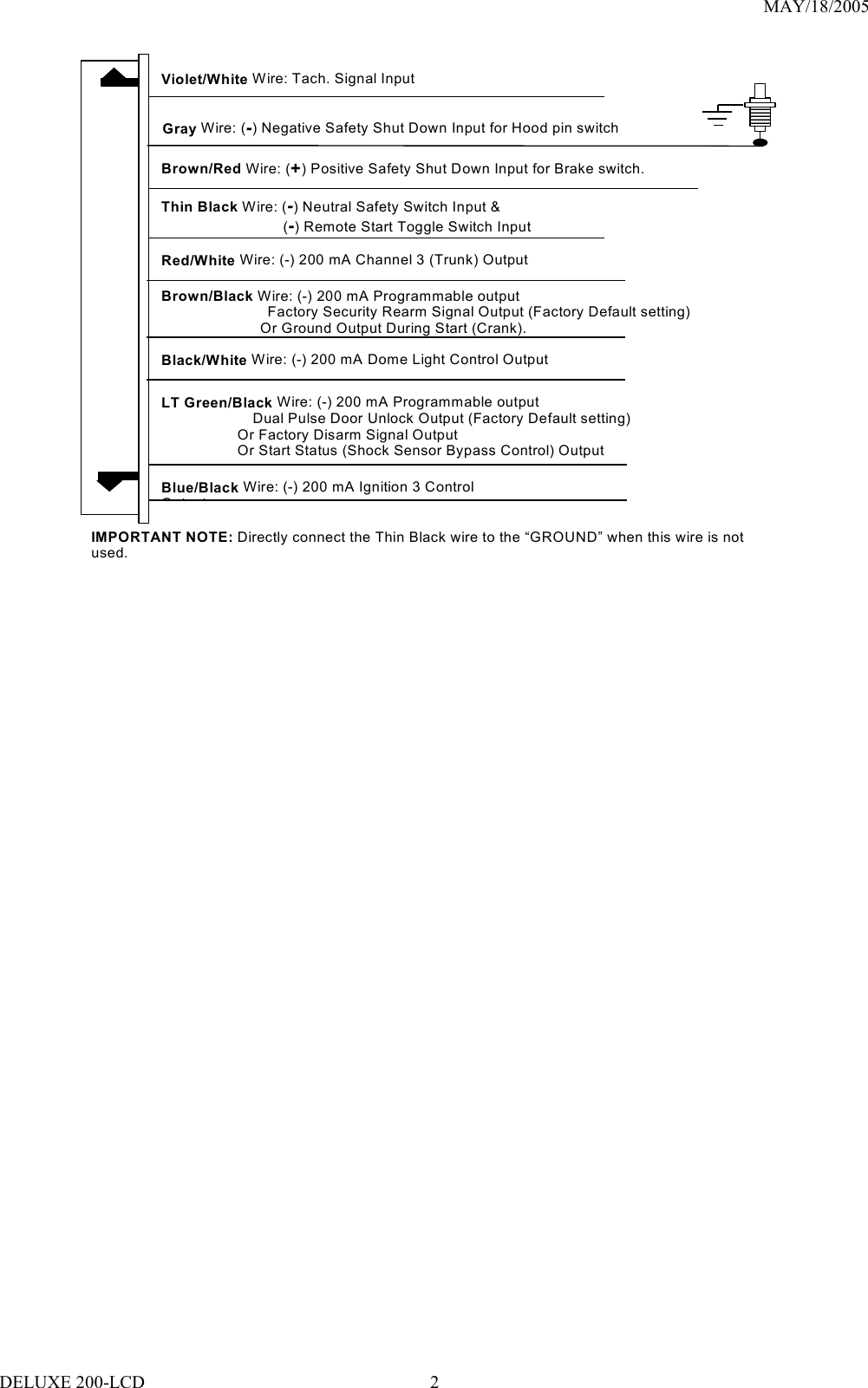
![MAY/18/2005 DELUXE 200 REMOTE ENGINE STARTER WITH KEYLESS ENTRY SYSTEM INSTALLATION MANUAL INTRODUCTION INSTALLER WARNINGS This Remote Starter with Alarm System is designed to be installed on fuel injected vehicles ONLY. ! For automatic transmission vehicle, this system must be installed and wired through a safety switch it will not start in any forward or reverse gear. ! Some automatic transmission vehicle [mainly older GM vehicles with a purple starter wire] have a mechanical-type park safety switch instead of electrical safety switch. The mechanical type does not interrupt the starter circuit when the transmission is any gear and does not offer the 100% level of safety required for remote starting purposes. Therefore, our system should never be installed on any vehicle that uses a mechanical type park safety switch. ! For automatic transmission vehicle, once you install this system, you must verify that the vehicle will not start any forward or reverse gear. Regardless of the type of vehicle. ! Read operation manual for operating and programming routine. ! Do not install any component near the brake, gas pedal or steering linkage. ! Some vehicles have a factory installed transponder immobilizer system that can severely complicate the installation. There is possibility that this system can not be installed on some immobilizer equipped vehicles. ! Most vehicles have an SRS air bag system. Use extreme care and do not probe any wires of the SRS system. ! Disconnect the car battery before connecting work on the vehicle. ! Check behind panels before drilling any holes. Ensure that no wiring harness or other components are located behind the panels that would otherwise be damaged. ! Use conventional crimp lock, bullet on any wiring. Poor wiring, i.e. taped joints will possibly introduce unreliability into the alarm system and may result in false alarms or incorrect operation. ! Install wiring neatly under carpets or behind trim to prevent possible damage to wires. ! For the wire operates the current more than 10A. We suggest soldering all connection point. Do not use crimp lock type connectors or wire nuts. INSTALLATION DIAGRAM #H4. 9 PIN WIRE CONNECTION: DELUXE 200-LCD 1](https://usermanual.wiki/Advance-Security/TR13/User-Guide-554701-Page-1.png)
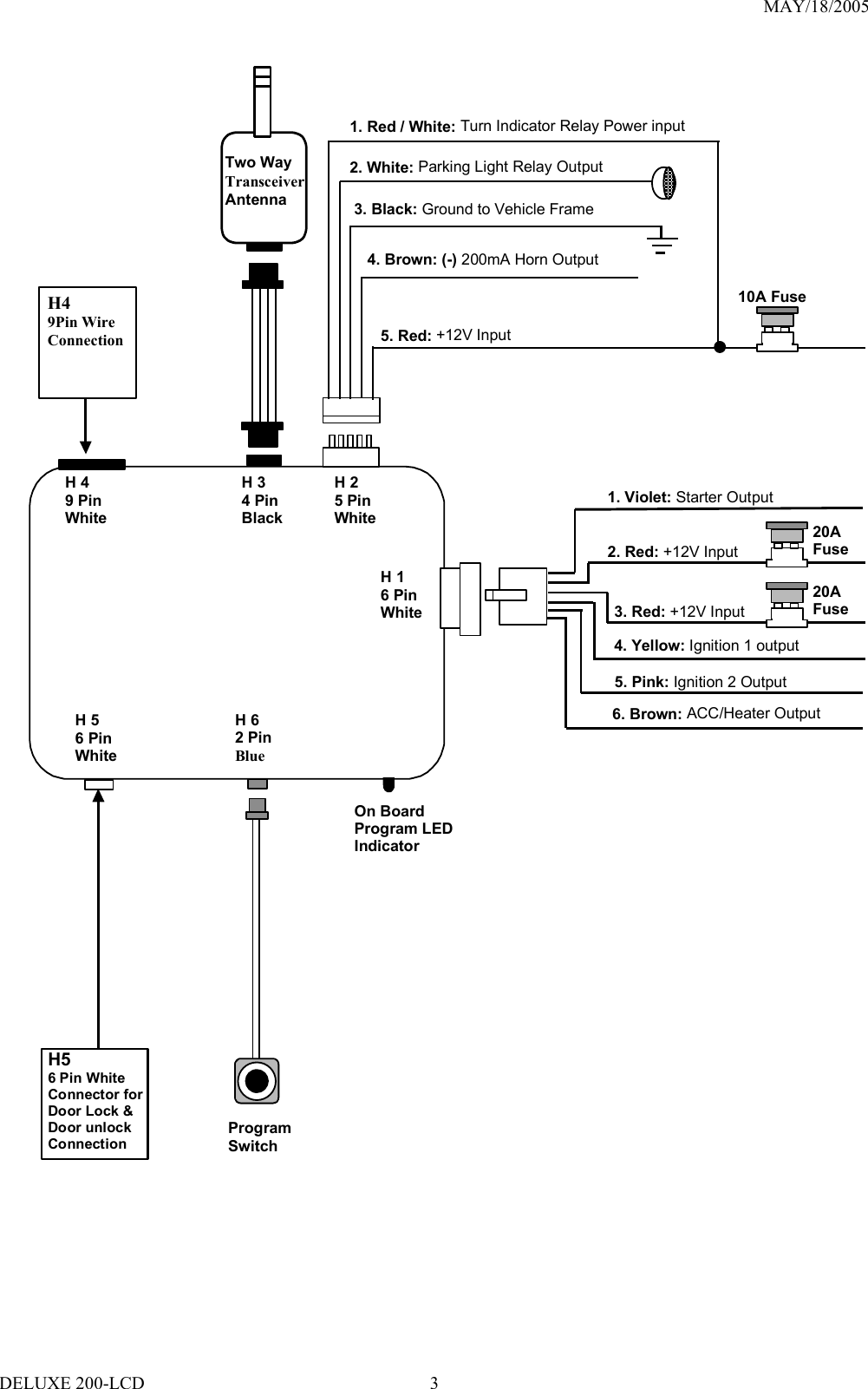
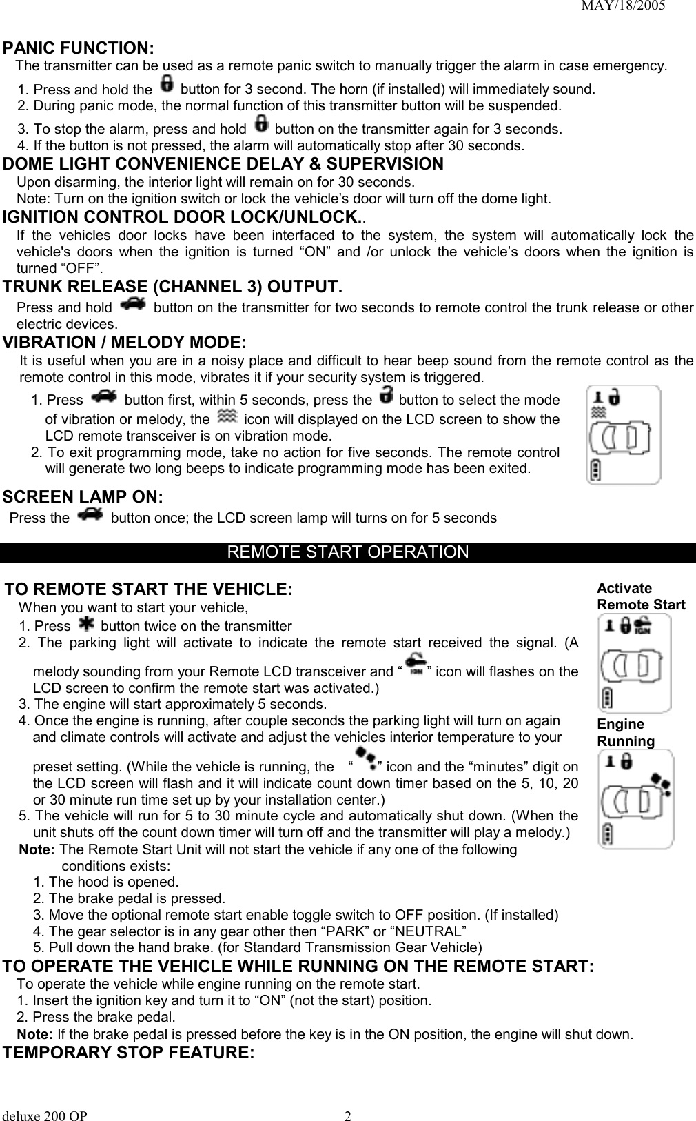
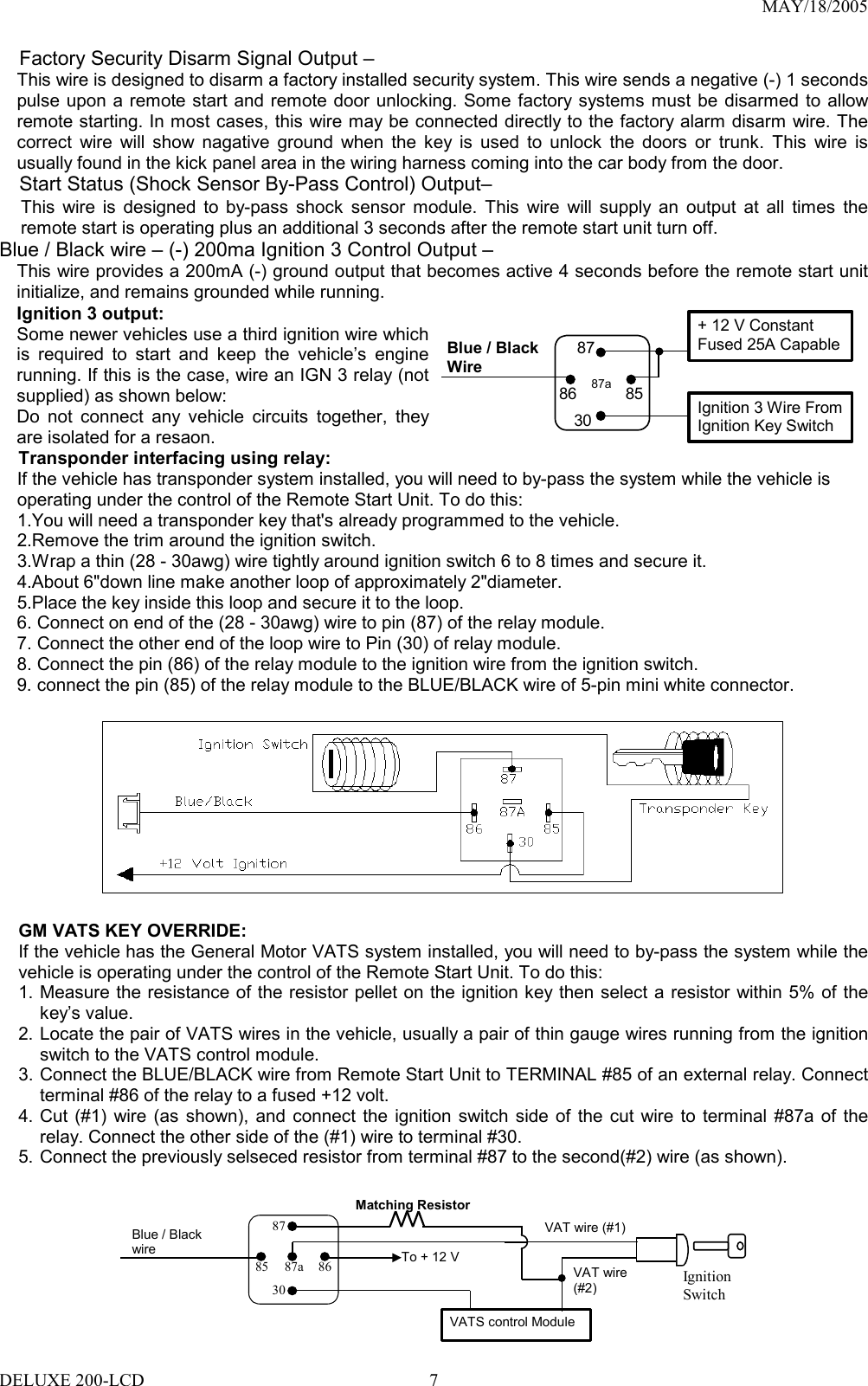
![MAY/18/2005 WIRING Keep wiring away from moving engine parts, exhaust pipes and high-tension cable. Tape wires that pass through holes on the firewall to prevent fraying. Watches out sharp edges that may damage wires and causes short circuit. CAUTION: Do not connect the wire harness to the control module until all wiring to vehicle is complete. 6 PIN HEAVY GAUGE WIRING CONNECTIONS: Remember that the system does to start a vehicle is duplicate the functions of the ignition key switch! Below, we will explain the three basic functions of the ignition switch. Since this installation will require analysis of the ignition switch functions, we recommend making the three connections below at the ignition switch harness directly. Violet wire – Starter Output – Careful consideration for the connection of this wire must be made to prevent the vehicle from starting while in gear. Understanding the difference between a mechanical and an electrical Neutral Start Switch will allow you to properly identify the circuit and select the correct installation method. In addition you will realize why the connection of the safety wire is required for all mechanical switch configurations. Failure to make this connection properly can result in personal injury and property damage. In all installations it is the responsibility of the installing technician to test the remote start unit and assure that the vehicle can not start via RF control in any gear selection other than park or neutral. In both mechanical and electrical neutral start switch configurations; the connection of the VIOLET wire will be made to the low current start solenoid wire of the ignition switch harness. This wire has +12 volts when the ignition switch is turned to the “START” (CRANK) position only. This wire have 0 volts in all other ignition switch positions. NOTE: This wire must be connected to the vehicle side of the starter cut relay (when used). For the electrical neutral switch configuration, this connection must be made between the starter inhibit relay (when used) and the neutral safety switch as shown in the following diagram. Failure to connect this wire to the ignition switch side of the neutral safety switch can result in personal injury and property damage. SEE NEUTRAL START SAFETY TEST FOR FURTHER DETAILS. Start Cut Relay(When Used)VIOLET WireClosed in Park or Neutral OnlyIgnitionSwitch“Start”“On” Neutral SafetySwitch“Acc”“Off” Starter Red wires – +12V Power Input – Remove the two 20A fuses prior to connecting these wires and do not replace them until the satellite has been plugged into the control module. These wires are the source of current for all the circuits the relay satellite will energize. They must be connected to a high current source. Since the factory supplies (+) 12V to the key switch that is used to operate the motor, it is recommended that these wires be connected there. Note: If the factory supplies two separate (+) 12V feeds to the ignition switch, connect one RED wire of the satellite to each feed at the switch. Yellow wire – Ignition Output – Connect the YELLOW wire to the ignition wire from the ignition switch. The ignition wire should receive "12 volts" when the ignition key is in the "ON" or “RUN” and "START" or “CRANK” position. When the ignition is turned "OFF", the ignition wire should receive "0" voltage. The YELLOW wire must be connected. Pink wire – Ignition 2 Output Some vehicles have [2] ignition wires that must be power. Connect the PINK wire to the ignition 2 wire from the ignition switch. The ignition wire should receive "12 volts" when the ignition key is in the "ON" or “RUN” and "START" or “CRANK” position. When the ignition is turned "OFF", the ignition wire should receive "0" voltage. If the PINK wire is not used, cap the end of the wire. Brown wire – Accessory Output (Heater /ACC Output) – Connect the BROWN wire to the accessory wire in the vehicle that powers the climate control system. An accessory wire will show + 12 volts when the ignition switch is turned to the “ACCESSORY” or “ON” and “RUN” positions, and will show 0 Volts when the key is turned to the “OFF” and “START” or “CRANK” position. There will often be more than one accessory wire in the ignition harness. The correct accessory DELUXE 200-LCD 4](https://usermanual.wiki/Advance-Security/TR13/User-Guide-554701-Page-4.png)
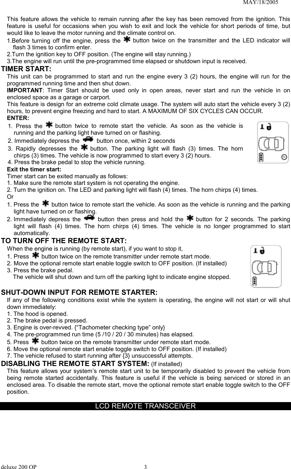
![MAY/18/2005 FEATURE “I” PRORAMMING: 1. Turn the Ignition 'switch ‘ON/OFF’ 3 TIMES and stay in OFF position. 2. Push the Program switch 2 times and holding in on 2nd push until one chirp with a long chirp is hearing and the LED start to flash then release the Program switch. You are now in the feature ‘I’ programming mode. 3. Press and release the transmitter button ‘A’ corresponding to the feature ‘A’ you want to program. a. The horn chirps and LED pause will indicate previously setting. b. The factory default settings is always [1] LED flash, [1] chirp. 4 Depress the transmitter button ‘A’ again to change the feature. Simple keep re-depressing the transmitter button ‘A’ again until the module advances to your desired setting. a. In this case, Press button ‘A’ again, the module would advance to [2] LED flash, [2] chirps. b. Press button ‘A’ again, the module would advance to [3] LED flash, [3] chirps etc. 5. Depress the transmitter button ‘B’ corresponding to the feature ‘B’ you wants to program. Press Transmitter Button One Chirp / LED one pulse Factory Default Setting Two Chirps / LED two pulses Three Chirps / LED three pulses Four Chirps / LED four pulses 1 Chirps on Chirps off 2 0.8-second Door lock pulses. 3.5-second Door lock pulse. Double pulse unlock Door lock with “Comfort Feature” 3 Ignition controlled door locks & unlocks Ignition controlled door locks only Ignition controlled door unlocks only Without ignition controlled door locks & unlocks 4 Without this feature Door lock before start Door lock after shut-down Door lock before start and Door lock after shut-down Exit: Turn Ignition to 'ON' position, or leave it for 15 seconds. A 3 long chirps & 3 parking light flashes to confirm exit. FEATURE “II” PRORAMMING: 1 Turn the Ignition switch ‘ON/OFF’ 3 TIMES and stay in OFF position. 2 Push the Program switch 4 times and holding in on the 4th push until two chirps with a long chirp is hearing and the LED start to flash then release the Program switch. You are now in the feature ‘II’ programming mode. 3 Press and release the transmitter button ‘A’ corresponding to the feature ‘A’ you want to program. Press Transmitter Button One Chirp / LED one pulse Factory Default Setting Two Chirps / LED two pulses Three Chirps / LED three pulses 1 Pathway illumination feature “off” Parking light turns “on” for 30- second upon an unlock signal Parking light turns “on” for 30- second upon an unlock signal & 10-second upon a lock signal. 2 Constant parking light output Flashing parking light output 3 Brown/Black Wire = Factory Security Rearm Signal Output Brown/ Black Wire = Ground Output During Start (Crank) 4 LT. Green / Black Wire = Dual Pulse door unlock output LT. Green / Black Wire = Factory Security Disarm Signal Output LT. Green / Black Wire = Start Status Output (Shock Sensor Bypass) Exit: Turn Ignition to 'ON' position, or leave it for 15 seconds. A 3 long chirps & 3 parking light flashes to confirm exit. FEATURE “III” PRORAMMING: 1. Turn the Ignition 'switch ‘ON/OFF’ 3 TIMES and stay in OFF position. 2. Push the Program switch 6 times and holding in on the 6th push until three chirps with a long chirp is hearing and the LED start to flash then release the Program switch. You are now in the feature ‘III’ programming mode. 3. Press and release the transmitter button ‘A’ corresponding to the feature ‘A’ you want to program. DELUXE 200-LCD 10](https://usermanual.wiki/Advance-Security/TR13/User-Guide-554701-Page-10.png)
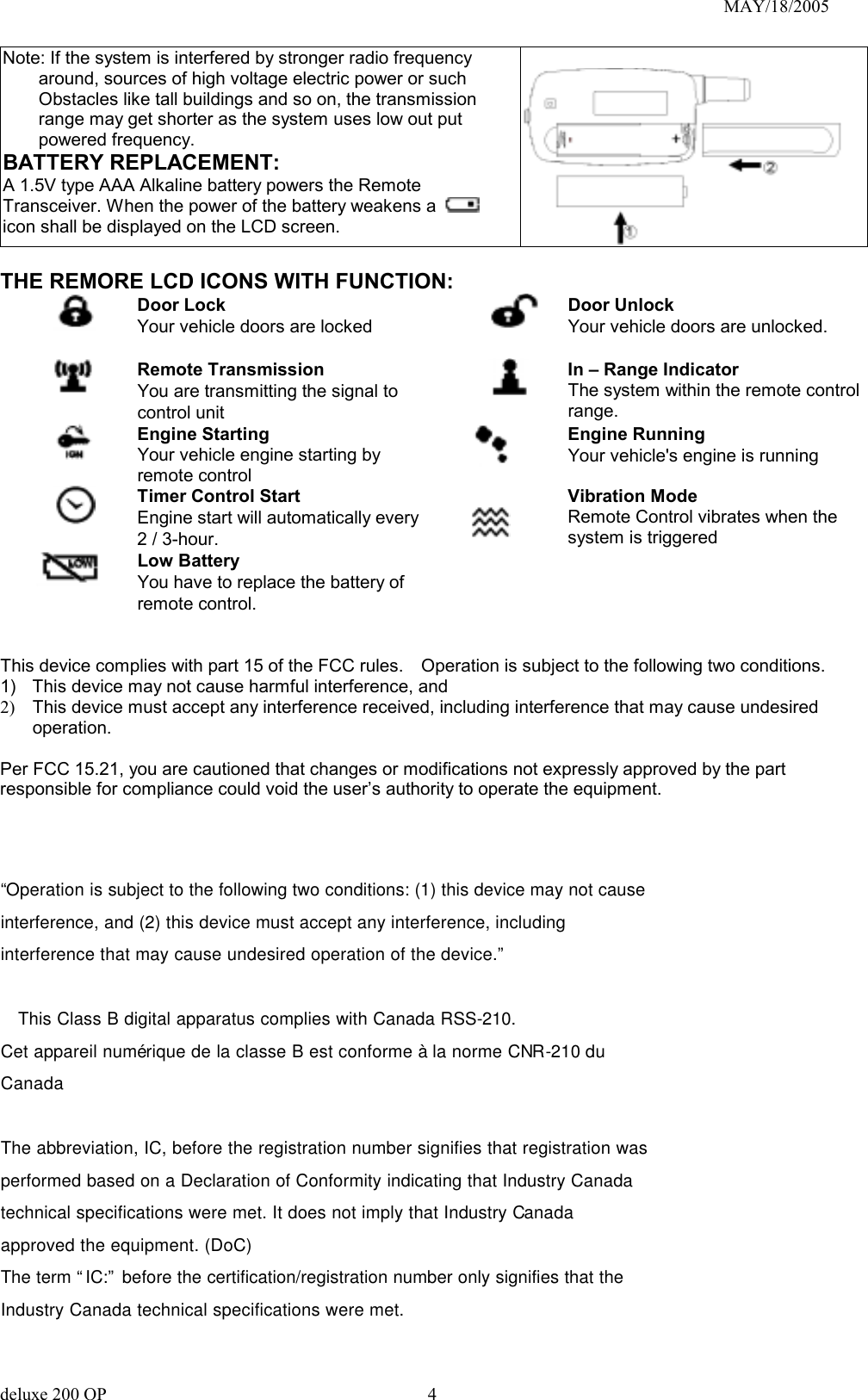
![MAY/18/2005 Press Transmitter Button One Chirp / LED one pulse Factory Default Setting Two Chirps / LED two pulse Three Chirps / LED three pulse Four Chirps / LED four pulse 1 Gasoline Engine Diesel Engine and 10 seconds warn-up timer Diesel Engine and 15 seconds warn-up timer Diesel Engine and 20 seconds warn-up timer 2 20 minutes run time 30 minutes run time 5 minutes run time 10 minutes run time3 Factory alarm disarm with channel 3 on Without this feature 4 3 Hour Time start 2 Hour Time Start Exit: Turn Ignition to 'ON' position, or leave it for 15 seconds. A 3 long chirps & 3 parking light flashes to confirm exit. FEATURE “IV” PRORAMMING: 1. Turn the Ignition 'switch ‘ON/OFF’ 3 TIMES and stay in OFF position. 2. Push the Program switch 8 times and holding in on the 8th push until four chirps with a long chirp is hearing and the LED start to flash then release the Program switch. You are now in the Start feature ‘IV’ programming mode. 3. Press and release the transmitter button ‘A’ corresponding to the feature ‘A’ you want to program. Press Transmitter Button One Chirp / LED one pulse Factory Default Setting Two Chirps / LED two pulse Three Chirps / LED three pulse Four Chirps / LED four pulse 1 Exit the programming mode. (3 long chirp & 3 parking light flashes to confirm this exit.) 2 + Engine Checking Voltage. Engine Checking TACH. / RPM Learning Mode 3 Start Timer: 0.6-second 0.8-second (2 chirps), 1.0-second (3 chirps), 1.2-second (4 chirps), 1.4-second (5 chirps), 1.6-second (6 chirps), 1.8-second (7 chirps), 2.0-second (8 chirps), 3.0-second (9 chirps), 4.0-second (10 chirps),4 Low check level for “Engine checking Tach.” Hi check level for “Engine checking Voltage.” Hi check level for “Engine checking Tach.” Low check level for “Engine checking Voltage.” Exit: Press the button on the transmitter. A 3 long chirps & 3 parking light flashes to confirm exit. ENGINE CHECKING TACH. / RPM LEARNING IMPORTANT NOTE: You must program the “Tach Signal” before trying to remote start. 1. Turn the Ignition switch ‘ON/OFF’ 3 TIMES and stay in OFF position. 2. Push the Program switch 8 times and holding in on the 8th push until four chirps with a long chirp is hearing and the LED start to flash then release the Program switch. 3. Press and release the transmitter and buttons at the same time twice [2] LED flash, [2] chirp to confirm the system in features “RPM Learning mode”. 4. Within 10 seconds, start the vehicle with the key. (While the engine is running, the parking & LED will flash, If don’t, please check VIOLET/WHITE wire connection. 5. Press and hold the Program switch for 2 seconds until a long chirp and the LED / the parking light will constantly on for two seconds. The RPM signal is learned. 6. Turns off the ignition switch to stop engine running. Once you complete step 6, you can adjust and test “Check Level” as below: CHECK LEVEL PROGRAMMING: (TEST and ADJUST) 1. Press the button twice on the transmitter to start the vehicle. 2. If everything goes well: DELUXE 200-LCD 11](https://usermanual.wiki/Advance-Security/TR13/User-Guide-554701-Page-11.png)
![MAY/18/2005 a. Press the button twice on the transmitter to stop engine running. You have been completed this programming successfully. b. Press button on the transmitter to exit the program mode. There will be 3 long chirps & 3 parking light flashes for confirmation. 3. If the crank time is too short, (Engine not running, while stops cranks): a. Press the button on the transmitter to stop engine running. Press button on the transmitter to set proper “Check Level ” to Hi position. [2] LED flashes, [2] chirps to confirm this setting b. Repeat the step1 – 4. 4. If the crank time is too long, (Engine already successfully running, while still cranks): a. Press the button on the transmitter to stop engine running. Press button on the transmitter to set proper “ Check Level ” to Low position. [1] LED flash, [1] chirp to confirm this setting b. Repeat the step1 – 4. c. ENGINE CHECKING VOLTAGE Important Note: The “Check Level” for most vehicles would be set in “Hi Check Level”, while in “Engine Check Voltage mode”, the “Check Level” must be set at “HI” position first. 1. Turn the Ignition 'switch ‘ON/OFF’ 3 TIMES and stay in OFF position. 2. Push the Program switch 8 times and holding in on the 8th push until four chirps with a long chirp is hearing and the LED start to flash then release the Program switch. 3. Press the transmitter and buttons at the same time to set the “Engine Checking Voltage”. [1] LED flashes, [1] chirps to confirm this setting Once you complete step 3, you can adjust and test “Start Timer” as below: START TIMER PROGRAMMING: (TEST and ADJUST) 1. Press the button twice on the transmitter to start the vehicle. 2. If everything goes well: Wait for 15 seconds: a. If the engine still running. I. Press the button twice on the transmitter to stop engine running. You have been completed this programming successfully. II. Press button on the transmitter to exit the program mode. There will be 3 long chirps & 3 parking light flashes for confirmation. b. If the engine shut down after the vehicle has been started. I. Press the button twice on the transmitter to stop engine running. II. Press button on the transmitter to set “Check Level” to LOW position. [1] LED flash, [1] chirp to confirm this setting III. Repeat the step1 – 2. 3. If the crank time is too long, (Engine already successfully running, while still cranks): a. Press the button twice on the transmitter to stop engine running. b. Press button on the transmitter to set proper “Start Timer”. The chirp & LED pause will confirm this enters. (Decrease “Start Timer” is necessary.) c. Repeat the step1 – 4. 4. If the crank time is too short, (Engine not running, while stops cranks): a. Press the button twice on the transmitter to stop engine running. b. Press button on the transmitter to set proper “Start Timer”. The chirp & LED pause will confirm this enters. (Increase “Start Timer ” is necessary.) c. Repeat the step1 – 4. d. RETURN TO FACTORY DEFAULT SETTING 1. Turn the ignition ON then OFF 3 TIMES and stay in OFF position. 2. Push the Program switch 12 times and holding in on the 12th push until six chirp with a long chirp is hearing and the LED start to flash then release the Program switch. You are now in the “Return To Factory Default Setting” programming mode. 3. Press and hold the and buttons at the same time on the transmitter for 5 seconds, there will be a confirmation six chirp with 3 long chirp and the LED turns On for 2 seconds to confirm the system Feature Programming all returns to factory default setting. DELUXE 200-LCD 12](https://usermanual.wiki/Advance-Security/TR13/User-Guide-554701-Page-12.png)