Advance Security TR13 Car Alarm Transceiver User Manual MODEL 6876
Advance Security Inc Car Alarm Transceiver MODEL 6876
Users Manual

MAY/18/2005
DELUXE 200
REMOTE ENGINE STARTER
WITH KEYLESS ENTRY SYSTEM
INSTALLATION MANUAL
INTRODUCTION
INSTALLER WARNINGS
This Remote Starter with Alarm System is designed to be installed on fuel injected vehicles ONLY.
! For automatic transmission vehicle, this system must be installed and wired through a safety switch it will
not start in any forward or reverse gear.
! Some automatic transmission vehicle [mainly older GM vehicles with a purple starter wire] have a
mechanical-type park safety switch instead of electrical safety switch. The mechanical type does not
interrupt the starter circuit when the transmission is any gear and does not offer the 100% level of safety
required for remote starting purposes. Therefore, our system should never be installed on any vehicle that
uses a mechanical type park safety switch.
! For automatic transmission vehicle, once you install this system, you must verify that the vehicle will not
start any forward or reverse gear. Regardless of the type of vehicle.
! Read operation manual for operating and programming routine.
! Do not install any component near the brake, gas pedal or steering linkage.
! Some vehicles have a factory installed transponder immobilizer system that can severely complicate the
installation. There is possibility that this system can not be installed on some immobilizer equipped vehicles.
! Most vehicles have an SRS air bag system. Use extreme care and do not probe any wires of the SRS
system.
! Disconnect the car battery before connecting work on the vehicle.
! Check behind panels before drilling any holes. Ensure that no wiring harness or other components are
located behind the panels that would otherwise be damaged.
! Use conventional crimp lock, bullet on any wiring. Poor wiring, i.e. taped joints will possibly introduce
unreliability into the alarm system and may result in false alarms or incorrect operation.
! Install wiring neatly under carpets or behind trim to prevent possible damage to wires.
! For the wire operates the current more than 10A. We suggest soldering all connection point. Do not use
crimp lock type connectors or wire nuts.
INSTALLATION DIAGRAM
#H4. 9 PIN WIRE CONNECTION:
DELUXE 200-LCD
1
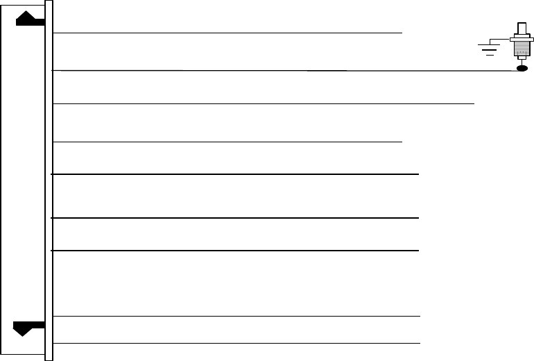
MAY/18/2005
Brown/Red Wire: (+) Positive Safety Shut Down Input for Brake switch.
Thin Black Wire: (-) Neutral Safety Switch Input &
(-) Remote Start Toggle Switch Input
Violet/White Wire: Tach. Signal Input
Gray Wire: (-) Negative Safety Shut Down Input for Hood pin switch
IMPORTANT NOTE: Directly connect the Thin Black wire to the “GROUND” when this wire is not
used.
Black/White Wire: (-) 200 mA Dome Light Control Output
Red/White Wire: (-) 200 mA Channel 3 (Trunk) Output
Blue/Black Wire: (-) 200 mA Ignition 3 Control
Ot t
LT Green/Black Wire: (-) 200 mA Programmable output
Dual Pulse Door Unlock Output (Factory Default setting)
Or Factory Disarm Signal Output
Or Start Status (Shock Sensor Bypass Control) Output
Brown/Black Wire: (-) 200 mA Programmable output
Factory Security Rearm Signal Output (Factory Default setting)
Or Ground Output During Start (Crank).
DELUXE 200-LCD
2
MAY/18/2005
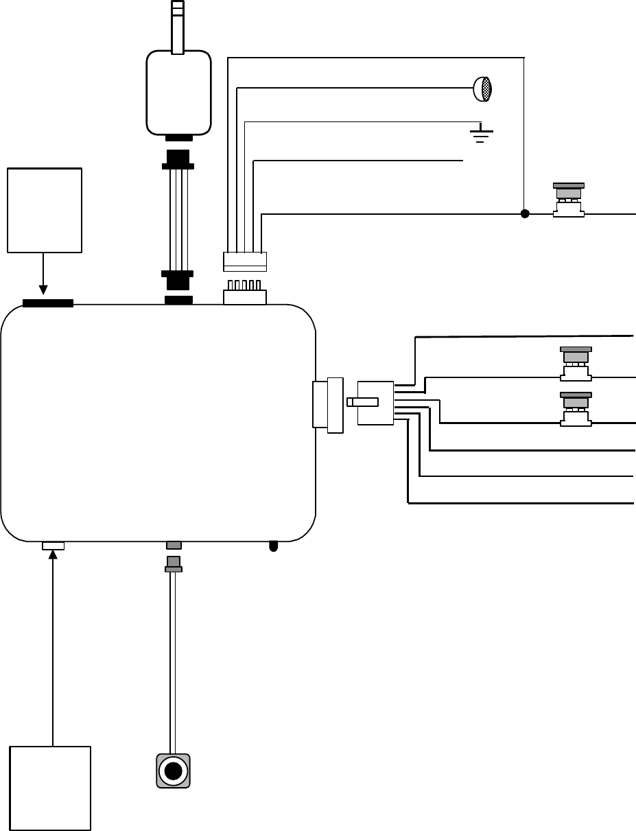
H4
9Pin Wire
Connection
H 1
6 Pin
White
H 2
5 Pin
White
H 3
4 Pin
Black
H 4
9 Pin
White
Program
Switch
H 6
2 Pin
Blue
1. Red / White: Turn Indicator Relay Power input
2. White: Parking Light Relay Output
3. Black: Ground to Vehicle Frame
4. Brown: (-) 200mA Horn Output
5. Red: +12V Input
Two Way
Transceiver
Antenna
On Board
Program LED
Indicator
10A Fuse
2. Red: +12V Input
3. Red: +12V Input
4. Yellow: Ignition 1 output
1. Violet: Starter Output
20A
Fuse
20A
Fuse
5. Pink: Ignition 2 Output
H 5
6 Pin
White
H5
6 Pin White
Connector for
Door Lock &
Door unlock
Connection
6. Brown: ACC/Heater Output
DELUXE 200-LCD
3
MAY/18/2005
WIRING
Keep wiring away from moving engine parts, exhaust pipes and high-tension cable. Tape wires that pass
through holes on the firewall to prevent fraying. Watches out sharp edges that may damage wires and causes
short circuit.
CAUTION: Do not connect the wire harness to the control module until all wiring to vehicle is complete.
6 PIN HEAVY GAUGE WIRING CONNECTIONS:
Remember that the system does to start a vehicle is duplicate the functions of the ignition key switch! Below,
we will explain the three basic functions of the ignition switch. Since this installation will require analysis of the
ignition switch functions, we recommend making the three connections below at the ignition switch harness
directly.
Violet wire – Starter Output –
Careful consideration for the connection of this wire must be made to prevent the vehicle from starting
while in gear. Understanding the difference between a mechanical and an electrical Neutral Start Switch
will allow you to properly identify the circuit and select the correct installation method. In addition you will
realize why the connection of the safety wire is required for all mechanical switch configurations.
Failure to make this connection properly can result in personal injury and property damage.
In all installations it is the responsibility of the installing technician to test the remote start unit and assure
that the vehicle can not start via RF control in any gear selection other than park or neutral.
In both mechanical and electrical neutral start switch configurations; the connection of the VIOLET wire will
be made to the low current start solenoid wire of the ignition switch harness. This wire has +12 volts when
the ignition switch is turned to the “START” (CRANK) position only. This wire have 0 volts in all other
ignition switch positions.
NOTE: This wire must be connected to the vehicle side of the starter cut relay (when used). For the
electrical neutral switch configuration, this connection must be made between the starter inhibit relay (when
used) and the neutral safety switch as shown in the following diagram.
Failure to connect this wire to the ignition switch side of the neutral safety switch can result in personal
injury and property damage. SEE NEUTRAL START SAFETY TEST FOR FURTHER DETAILS.
Start Cut Relay
(When Used)
V
IOLET Wire
Closed in Park or
Neutral Only
Ignition
Switch
“Start”
“On” Neutral Safety
Switch
“Acc”
“Off” Starter
Red wires – +12V Power Input –
Remove the two 20A fuses prior to connecting these wires and do not replace them until the satellite has
been plugged into the control module. These wires are the source of current for all the circuits the relay
satellite will energize. They must be connected to a high current source. Since the factory supplies (+) 12V
to the key switch that is used to operate the motor, it is recommended that these wires be connected there.
Note: If the factory supplies two separate (+) 12V feeds to the ignition switch, connect one RED wire of the
satellite to each feed at the switch.
Yellow wire – Ignition Output –
Connect the YELLOW wire to the ignition wire from the ignition switch. The ignition wire should receive "12
volts" when the ignition key is in the "ON" or “RUN” and "START" or “CRANK” position. When the ignition is
turned "OFF", the ignition wire should receive "0" voltage. The YELLOW wire must be connected.
Pink wire – Ignition 2 Output
Some vehicles have [2] ignition wires that must be power. Connect the PINK wire to the ignition 2 wire from
the ignition switch. The ignition wire should receive "12 volts" when the ignition key is in the "ON" or “RUN”
and "START" or “CRANK” position. When the ignition is turned "OFF", the ignition wire should receive "0"
voltage. If the PINK wire is not used, cap the end of the wire.
Brown wire – Accessory Output (Heater /ACC Output) –
Connect the BROWN wire to the accessory wire in the vehicle that powers the climate control system.
An accessory wire will show + 12 volts when the ignition switch is turned to the “ACCESSORY” or “ON” and
“RUN” positions, and will show 0 Volts when the key is turned to the “OFF” and “START” or “CRANK”
position. There will often be more than one accessory wire in the ignition harness. The correct accessory
DELUXE 200-LCD
4
MAY/18/2005
wire will power the vehicle’s climate control system. Some vehicle may have separate wires for the blower
motor and the air conditioning compressor. In such cases, it will be necessary to add a relay to power the
second accessory wire.
5 PIN WIRE HARNESS:
Red / White wire – Parking Light Relay Power Input –
The RED/WHITE wire is the input to the flashing parking light relay. The connection of the RED/WHITE
wire will determine the output polarity of the flashing parking light relay.
If the vehicle you are working on has +12volt switched parking light, you don’t need connect this wire. This
wire already connected to +12 volt.
If the vehicle’s parking light are ground switched, cut the RED/WHITE wire, connect the RED/WHITE wire
to chassis ground.
White wire – Parking Light Relay Output (10A power output) –
Connect the WHITE wire to the parking light wire coming from the headlight switch. Do not connect the
WHITE wire to the dashboard lighting dimmer switch. (Damage to the dimmer will result). The limitation of
the WHITE wire is 10 AMP max. Do not exceed this limit or damage to the alarm and parking relay will
result.
Black wire – System Ground –
This is main ground connection of the alarm module. Make this connection to a solid section of the vehicle
frame. Do not connect this wire to any existing ground wires supplied by the factory wire loom, make the
connection to the vehicle's frame directly.
Brown wire – (-) 200mA Horn Output –
This wire is provided to use the existing vehicle's horn as the keyless entry system's optional's warning
audible device. It's a transistorized low current output, and should only be connected to the low current
ground output from the vehicle's horn switch.
Red wire – System Power (+12V Constant) –
The RED wire supplies power to the system. Connect this wire to a constant +12 volt source.
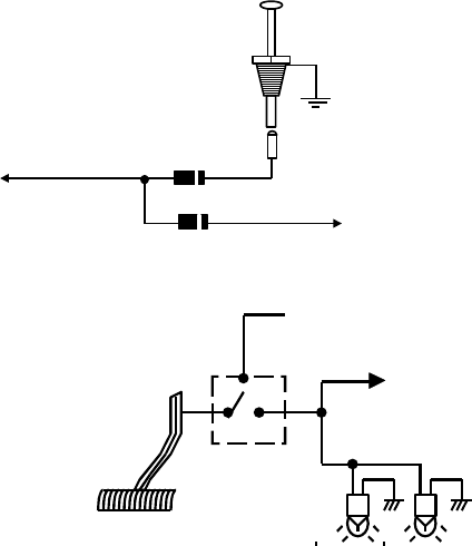
BLACK 4-PIN CONNECTOR. – TWO-WAY TRANSCEIVER/ANTENNA MODULE
The Two-way transceiver/antenna mounts on the location above the belt line (dashboard) of the vehicle for
best reception. We suggest you mount it on the lower left or upper left-hand side of windshield.
Warning! Do not mount in such a manner that it obstructs the driver’s view.
- Remove the protective tape backing.
- Carefully align the two-way transceiver/antenna and apply to windshield.
- Route the black connector wire behind the trim and connect to the two-way transceiver/antenna.
- Connect the other end to the control module.
- Special considerations must be made for windshield glass as some newer vehicles utilize a metallic
shielded window glass that will inhibit or restrict RF reception. In these vehicles, route the two ways
transceiver/antenna module away from metallic shielded window glass as far as possible.
9 PIN WIRE CONNECTORS:
Violet / White wire – Tach. Input Connection –
Note: You should connect this wire if you program the Feature IV – 2 to “Engine Checking TACH.”
otherwise not to connect this wire and tap the end.
Note: No connection of this wire is required, if you use the voltage checking type mode.
This input provides the remote start system with information about the engine’s revolutions per minute
(RPM). It can be connected to the negative side of the coil in vehicle with conventional coils. In multi-coil
and high energy ignition system locating a proper signal may be more difficult. Once connected,
To test for a tachometer wire, a multi-meter capable of test AC voltage must be used. The tach wire will
show between 1V and 6V AC at idle, and will increase as engine RPM increases. In multi-coil ignition
system, the system can learn individual coil wire. Individual coil wires in a multi-coil ignition system will
register lower amounts of AC voltage. Also, if necessary, the system can use a fuel injector control wire for
engine speed sensing. Common locations for a tach. wire are the ignition coils itself, the back of the
gauges, engine computers, and automatic transmission computers.
IMPORTANT! Do not test tacho. wires with a test light or logic probe. The vehicle will be damaged.
How to find a tach. wire with your multi-meter
1. Set the ACV or AC voltage (12V or 20V is fine.)
2. Attach the (-) probe of the meter to chassis ground.
3. Start and run the vehicle.
4. Probe the wire you suspect of being the tach. wire with the red probe of the meter.
5. If this is the correct wire the meter will read between 1V and 6V.
DELUXE 200-LCD
5
MAY/18/2005
IMPORTANT NOTE: You must program the “Tach Signal” before trying to remote start.
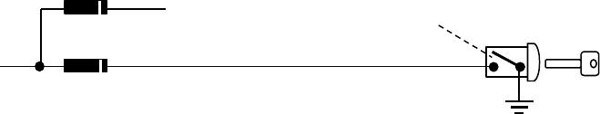
Grey wire – (-) Negative Safety Shut Down For Hood Pin Switch –
This wire provides an instant shutdown for the remote start, whenever it is grounded. Connect the wire to
the hood pin switch previously installed. This wire must be routed though a grommet in the firewall and
connected to the hood pin switch.
Important! This connection is a safety wire and
must be connected as shown and tested as
specifiled. Failure to do so may result in personal
injury or property damage. See detail of wiring in
the following diagram. This wire may also be
used if the vehicle brake light circuit switches
ground to the brake lights. An isolation diode
must be used for ground switched brake light
circuits and must be connected to the output of
the brake switch.
To Vehicle Brake Switch
Hood Pin Switch
Diode
To: Grey Wire /
Negative safety
Brown / Red wire – (+) Positive Safety Shut Down For Brake –
This wire provides an instant shutdown for the remote
start, whenever it gets +12volts. If the brake lights switch
in the vehicle switches +12 volts to the brake light circuit,
connect this wire to the output side of the brake switch.
This will allow the remote start to shut down if an attempt
is made to operate the vehicle without the key while
running under the control of the remote start. In most
vehicles, in order to shift gear, the brake pedal must be
depressed. The brake input will in turn cause the remote
start unit to shut off. See below diagram.
+12 volts from fuse box
To Brown / Red
wire
Brake light bulbs
Switch closes
When brake is
de
p
ress
Thin Black wire – (-) Neutral Safety Switch or (-) Remote Toggle Switch Input –
When the THIN BLACK wire is grounded, the remote start unit is operable. When this wire is open from
ground, the remote start is disabling.
1. The optional “remote start toggle switch” can be added on to temporarily disable the Remote Start
Device, it can prevent the vehicle from being remote started accidentally. This feature is useful if the
vehicle is being serviced or stored in an enclosed area. To disable the remote start, move the optional
remote start enable toggle switch to the OFF position. To enable the remote start, move the optional
remote start enable toggle switch to the ON position.
2. If needed, This wire can connect to the PARK/NEUTRAL switch in the vehicle. (See the TESTING
YOUR INSTALLATION GUIDE)
IMPORTANT NOTE: Directly connect the THIN BLACK wire to the “GROUND” when this wire is not
used.
Red / White wire – (-) 200ma Channel 3 (Trunk) Output –
This will become a 1 second pulse ground by activate channel 3 on transmitter for two seconds, the current
capacity of this wire is 200 mA. This feature allows you to remote control trunk release or other electric
device.
Brown / Black wire – (-) 200mA Factory Security Rearm Signal / Key Sensor Output –
Factory Security Rearm Signal Output (Factory default setting.)
This output is programmable. If programmed rearm a factory installed security system. This wire will
supply a pulse whenever the remote start times out or is shut dowm using the transmitter and remote door
locking..
Ground Output During Start (Crank)
This wire will provide a 200mA ground output while the starter output of the remote start unit is active. This
output can be used to activate the Crank Low/Bulb Test wire found in some GM vehicles. This wire is also
referred to as the ECM wake up wire in some vehicles.
Black / White wire – (-) 200mA Dome Light Supervision Output –
This wire becomes grounded when the dome light controls circuit active. The current capacity of this wire is
200mA. This wire can control the operation of the interior lights. An optional 10 Amps relay can be used to
this system for interior lights operation. Upon disarming, the interior lights will remain on for 30 seconds.
LT. Green / Black wire – (-) 200ma Programmable Output –
Dual Pulse Door Unlock Output – (Factory default setting)
The dual pulse door unlock feature will work for the most fully electronic door lock circuit. The vehicle must
have an electronic door lock switch (not the lock knob or key switch), which locks and unlocks all of
vehicle's doors. When wired for this feature, press the disarm (or unlock) button one time will disarm the
alarm and unlock the driver's door only. If, press disarm (or unlock) button two times within 3 seconds, the
alarm will disarm and all doors will unlock.
DELUXE 200-LCD
6
MAY/18/2005
Factory Security Disarm Signal Output –
This wire is designed to disarm a factory installed security system. This wire sends a negative (-) 1 seconds
pulse upon a remote start and remote door unlocking. Some factory systems must be disarmed to allow
remote starting. In most cases, this wire may be connected directly to the factory alarm disarm wire. The
correct wire will show nagative ground when the key is used to unlock the doors or trunk. This wire is
usually found in the kick panel area in the wiring harness coming into the car body from the door.
Start Status (Shock Sensor By-Pass Control) Output–
This wire is designed to by-pass shock sensor module. This wire will supply an output at all times the
remote start is operating plus an additional 3 seconds after the remote start unit turn off.
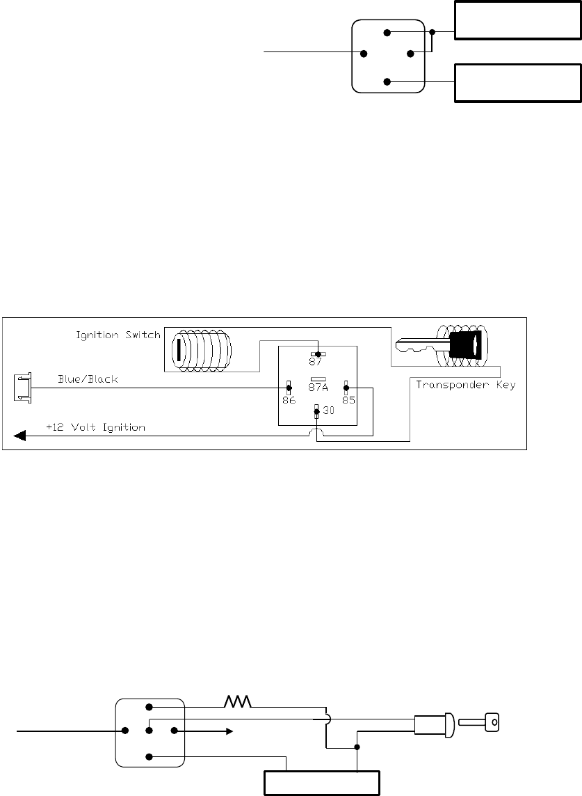
Blue / Black wire – (-) 200ma Ignition 3 Control Output –
This wire provides a 200mA (-) ground output that becomes active 4 seconds before the remote start unit
initialize, and remains grounded while running.
Ignition 3 output:
Some newer vehicles use a third ignition wire which
is required to start and keep the vehicle’s engine
running. If this is the case, wire an IGN 3 relay (not
supplied) as shown below:
Do not connect any vehicle circuits together, they
are isolated for a resaon.
Blue / Black
Wire
87a
Ignition 3 Wire From
Ignition Key Switch
+ 12 V Constant
Fused 25A Capable
30
8586
87
Transponder interfacing using relay:
If the vehicle has transponder system installed, you will need to by-pass the system while the vehicle is
operating under the control of the Remote Start Unit. To do this:
1.You will need a transponder key that's already programmed to the vehicle.
2.Remove the trim around the ignition switch.
3.Wrap a thin (28 - 30awg) wire tightly around ignition switch 6 to 8 times and secure it.
4.About 6"down line make another loop of approximately 2"diameter.
5.Place the key inside this loop and secure it to the loop.
6. Connect on end of the (28 - 30awg) wire to pin (87) of the relay module.
7. Connect the other end of the loop wire to Pin (30) of relay module.
8. Connect the pin (86) of the relay module to the ignition wire from the ignition switch.
9. connect the pin (85) of the relay module to the BLUE/BLACK wire of 5-pin mini white connector.
GM VATS KEY OVERRIDE:
If the vehicle has the General Motor VATS system installed, you will need to by-pass the system while the
vehicle is operating under the control of the Remote Start Unit. To do this:
1. Measure the resistance of the resistor pellet on the ignition key then select a resistor within 5% of the
key’s value.
2. Locate the pair of VATS wires in the vehicle, usually a pair of thin gauge wires running from the ignition
switch to the VATS control module.
3. Connect the BLUE/BLACK wire from Remote Start Unit to TERMINAL #85 of an external relay. Connect
terminal #86 of the relay to a fused +12 volt.
4. Cut (#1) wire (as shown), and connect the ignition switch side of the cut wire to terminal #87a of the
relay. Connect the other side of the (#1) wire to terminal #30.
5. Connect the previously selseced resistor from terminal #87 to the second(#2) wire (as shown).
To + 12 V
Ignition
Switch
Blue / Black
wire
Matching Resistor
VATS control Module
87a 86
30
87
85
VAT wire (#1)
VAT wire
(
#2
)
DELUXE 200-LCD
7
MAY/18/2005
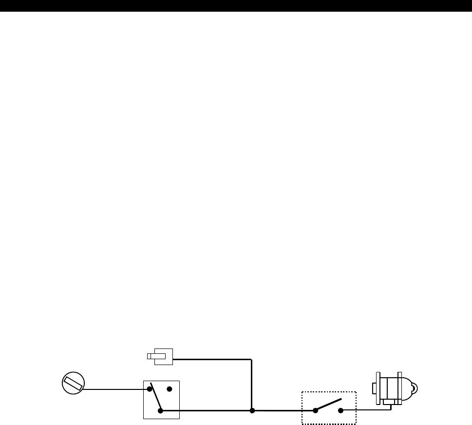
2 PIN BLUE CONNECTOR FOR THE PROGRAM SWITCH:
Select a mounting location for the switch that is easily accessible to the driver of the vehicle. The switch
does not have to be concealed. however, concealing the switch is always recommended. Route the
program switch wires to the control module.
6 PIN DOOR LOCK CONNECTOR:
Blue/White Wire:
(30) - Door Unlock Relay
Blue/Red Wire: (87a) - Door Unlock Relay
Blue/Yellow Wire: (87) - Door Unlock Relay
Green/Red Wire:
(87a) - Door Lock Relay
Green/White Wire:
(30) - Door Lock Relay
Green/Yellow Wire: (87) - Door Lock Relay
INSTALL NEW DOOR LOCK MOTORS
+12V
Green/ white
Blue/ white
Blue/ red
Green/ red
Green/ yellow
Blue/ yellow
N
EGATIVE TRIGGER DOOR LOCK SYSTEM
Blue / white
Green / white
Door Lock
Maste
r
Lockin g
Switch
Door unlock
Green / y ellow
Blue / y ellow
POSITIVE TRIGGER DOOR LOCK SYSTEM
Blue / white
Green / white
Door Lock
Master
Lockin g
Switch
Door unloc
k
Green /
y
ellow
Blue / yellow
+ 12V
+ 12V
ALTERNATING DOOR LOCKS
+12V
Master Door
Lock Switch
X
X
Splic
Splic Cut the
Existing
Lock Wire
To Door
Lock
To Slave Door
Lock switches
Green/ white
Green/ red
Cut the Existing
Unlock Wire
Blue/ white
Blue/ red
+ 12V
Green/ yellow
Blue/ yellow
VACUUM OPREATE DOOR LOCKING SYSTEM
Green/ white
Blue/ red
Green/ red
Blue/ white
Blue/ yellow
Green/ yellow
+12V
X
Cut
Compressor
Door Switch
DELUXE 200-LCD
8
MAY/18/2005
2 STEP DOOR UNLOCK WIRE CONNECTION FOR
5 WIRE ALTERNATING DOOR LOCKS
+12V
Cut the Existing
Lock Wire
Green / White
Blue / Red
Green / Red
Cut Existing Unlock
X
Blue / White
Cut the Unlock Wire
Lock
Unlock
OEM Door Master Lock
OEM Slave
Door Lock
Switch
+12V
LockUnlock
To All Other
Door Lock
Motors
LT. Green /
Black Wire
x
X
OEM
Door Lock
Motor
Blue / Yellow
Green / Yellow + 12V
+ 12V
85
86 87
87A
30
6-Pin
Door
Lock
Wire
Harness
VACUUM OPERATED DOOR LOCKING SYSTEM:
TYPICAL OF MERCEDES BENZ AND AUDI.
Locate the wire under the driver's kick panel. Use the
voltmeter connecting to ground, verify that you have th
e
correct wire with the doors unlocked, the voltmeter will
receive "12 volts". Lock the doors and the voltmeter wi
read "0 volt". Move the alligator clip to +12V and the
voltmeter will receive "12 volts". Cut this wire and mak
e
connections. Be sure to program door lock timer to
3.5 seconds. (See Feuture I – 2 Programming.)
2 STEP DOOR UNLOCK WIRE CONNECTION FOR
GROUND SWITCHED DOOR LOCKS
Cut Existin
g
Unlock
X
LockUnloc
k
OEM Door Master Lock Switch
To All Other
Door Lock
Motor
LT. Green / Black
Wire
OEM
Door Lock
Motor
Blue / White
Green / White
Green / Yellow
Existing
Lock Wire
Existing
Unlock Wire
6-Pin
Door
Lock
Wire
Harness
Blue / Red
Blue / Yellow +12V OEM Door
Lock Relay
2 STEP DOOR UNLOCK WIRE CONNECTION FOR
POSITIVE SWITCHED DOOR LOCKS
Cut Existing Unlock
X
LockUnlock
OEM Door Master Lock
To All Other
Door Lock
Motors
LT. Green /
Black Wire
OEM Driver's
Door Lock
Motor
+ 12V
Blue / Red
Existing Pos.
Lock Wire
Existing Pos.
Unlock Wire
30
87A
87
86 85
+12V
Blue / White
Green / White
Green / Yellow
Blue / Yellow + 12V
OEM Door
Lock Relay
6-Pin
Door
Lock
Wire
Harness
A. PROGRAMMING TRANSMITTER:
Note: This mode will only retain the last 4 remote transmitters programmed. If the transmitter memory is
exceeded, the security system will start deleting transmitters from memory in chronological order.
1. Turn the Ignition 'switch ‘OFF/ON’ 3 TIMES and stay in ON position. Within 15 seconds.
2. Push the Program switch 3 times and holding in on 3rd push until a long chirp is hearing and the LED
start to flash then release the Program switch. You are now in the Transmitter programming mode.
3. Press and hold any button of the transmitter until the horn responds with a confirming chirp / a flash from
parking light / the LED turns on for 2 seconds indicating the signal has been stored into memory.
4. If you have additional transmitters (up to 4) that need to be programmed, repeat step 3 for each
transmitter.
Exit: Turn Ignition to 'OFF' position, or leave it for 15 seconds. A 3 long chirps & 3 parking light flashes to
confirm exit.
B. FEATURES PROGRAMMING:
DELUXE 200-LCD
9
MAY/18/2005
FEATURE “I” PRORAMMING:
1. Turn the Ignition 'switch ‘ON/OFF’ 3 TIMES and stay in OFF position.
2. Push the Program switch 2 times and holding in on 2nd push until one chirp with a long chirp is hearing
and the LED start to flash then release the Program switch. You are now in the feature ‘I’ programming
mode.
3. Press and release the transmitter button ‘A’ corresponding to the feature ‘A’ you want to program.
a. The horn chirps and LED pause will indicate previously setting.
b. The factory default settings is always [1] LED flash, [1] chirp.
4 Depress the transmitter button ‘A’ again to change the feature. Simple keep re-depressing the transmitter
button ‘A’ again until the module advances to your desired setting.
a. In this case, Press button ‘A’ again, the module would advance to [2] LED flash, [2] chirps.
b. Press button ‘A’ again, the module would advance to [3] LED flash, [3] chirps etc.
5. Depress the transmitter button ‘B’ corresponding to the feature ‘B’ you wants to program.
Press
Transmitter
Button
One Chirp /
LED one pulse
Factory Default
Setting
Two Chirps /
LED two pulses
Three Chirps /
LED three pulses
Four Chirps /
LED four pulses
1 Chirps on Chirps off
2 0.8-second Door
lock pulses.
3.5-second Door lock
pulse.
Double pulse
unlock
Door lock with
“Comfort Feature”
3 Ignition controlled
door locks &
unlocks
Ignition controlled
door locks only
Ignition controlled
door unlocks only
Without ignition
controlled door
locks & unlocks
4 Without this feature Door lock before start Door lock after
shut-down
Door lock before
start and Door lock
after shut-down
Exit: Turn Ignition to 'ON' position, or leave it for 15 seconds. A 3 long chirps & 3 parking light flashes to
confirm exit.
FEATURE “II” PRORAMMING:
1 Turn the Ignition switch ‘ON/OFF’ 3 TIMES and stay in OFF position.
2 Push the Program switch 4 times and holding in on the 4th push until two chirps with a long chirp is
hearing and the LED start to flash then release the Program switch. You are now in the feature ‘II’
programming mode.
3 Press and release the transmitter button ‘A’ corresponding to the feature ‘A’ you want to program.
Press
Transmitter
Button
One Chirp / LED one pulse
Factory Default Setting
Two Chirps / LED two
pulses
Three Chirps / LED three
pulses
1 Pathway illumination feature
“off”
Parking light turns “on” for
30- second upon an unlock
signal
Parking light turns “on” for
30- second upon an unlock
signal & 10-second upon a
lock signal.
2 Constant parking light
output
Flashing parking light output
3 Brown/Black Wire = Factory
Security Rearm Signal
Output
Brown/ Black Wire =
Ground Output During Start
(Crank)
4 LT. Green / Black Wire =
Dual Pulse door unlock
output
LT. Green / Black Wire =
Factory Security Disarm
Signal Output
LT. Green / Black Wire =
Start Status Output
(Shock Sensor Bypass)
Exit: Turn Ignition to 'ON' position, or leave it for 15 seconds. A 3 long chirps & 3 parking light flashes to
confirm exit.
FEATURE “III” PRORAMMING:
1. Turn the Ignition 'switch ‘ON/OFF’ 3 TIMES and stay in OFF position.
2. Push the Program switch 6 times and holding in on the 6th push until three chirps with a long chirp is
hearing and the LED start to flash then release the Program switch. You are now in the feature ‘III’
programming mode.
3. Press and release the transmitter button ‘A’ corresponding to the feature ‘A’ you want to program.
DELUXE 200-LCD
10
MAY/18/2005
Press
Transmitter
Button
One Chirp /
LED one pulse
Factory Default
Setting
Two Chirps /
LED two pulse
Three Chirps /
LED three pulse
Four Chirps /
LED four pulse
1 Gasoline Engine Diesel Engine and
10 seconds warn-up
timer
Diesel Engine and
15 seconds warn-up
timer
Diesel Engine and
20 seconds warn-up
timer
2 20 minutes run time 30 minutes run time 5 minutes run time 10 minutes run time
3 Factory alarm
disarm with channel
3 on
Without this feature
4 3 Hour Time start 2 Hour Time Start
Exit: Turn Ignition to 'ON' position, or leave it for 15 seconds. A 3 long chirps & 3 parking light flashes to
confirm exit.
FEATURE “IV” PRORAMMING:
1. Turn the Ignition 'switch ‘ON/OFF’ 3 TIMES and stay in OFF position.
2. Push the Program switch 8 times and holding in on the 8th push until four chirps with a long chirp is
hearing and the LED start to flash then release the Program switch. You are now in the Start feature ‘IV’
programming mode.
3. Press and release the transmitter button ‘A’ corresponding to the feature ‘A’ you want to program.
Press
Transmitter
Button
One Chirp /
LED one pulse
Factory Default
Setting
Two Chirps /
LED two pulse
Three Chirps /
LED three pulse
Four Chirps /
LED four pulse
1 Exit the programming mode. (3 long chirp & 3 parking light flashes to confirm this exit.)
2 + Engine Checking
Voltage.
Engine Checking
TACH. /
RPM Learning Mode
3 Start Timer:
0.6-second
0.8-second (2 chirps), 1.0-second (3 chirps), 1.2-second (4 chirps),
1.4-second (5 chirps), 1.6-second (6 chirps), 1.8-second (7 chirps),
2.0-second (8 chirps), 3.0-second (9 chirps), 4.0-second (10 chirps),
4 Low check level for
“Engine checking
Tach.”
Hi check level for
“Engine checking
Voltage.”
Hi check level for
“Engine checking
Tach.”
Low check level for
“Engine checking
Voltage.”
Exit: Press the button on the transmitter. A 3 long chirps & 3 parking light flashes to confirm exit.
ENGINE CHECKING TACH. / RPM LEARNING
IMPORTANT NOTE: You must program the “Tach Signal” before trying to remote start.
1. Turn the Ignition switch ‘ON/OFF’ 3 TIMES and stay in OFF position.
2. Push the Program switch 8 times and holding in on the 8th push until four chirps with a long chirp is
hearing and the LED start to flash then release the Program switch.
3. Press and release the transmitter and buttons at the same time twice [2] LED flash, [2] chirp to
confirm the system in features “RPM Learning mode”.
4. Within 10 seconds, start the vehicle with the key. (While the engine is running, the parking & LED will
flash, If don’t, please check VIOLET/WHITE wire connection.
5. Press and hold the Program switch for 2 seconds until a long chirp and the LED / the parking light will
constantly on for two seconds. The RPM signal is learned.
6. Turns off the ignition switch to stop engine running.
Once you complete step 6, you can adjust and test “Check Level” as below:
CHECK LEVEL PROGRAMMING: (TEST and ADJUST)
1. Press the button twice on the transmitter to start the vehicle.
2. If everything goes well:
DELUXE 200-LCD
11
MAY/18/2005
a. Press the button twice on the transmitter to stop engine running. You have been completed this
programming successfully.
b. Press button on the transmitter to exit the program mode. There will be 3 long chirps & 3 parking
light flashes for confirmation.
3. If the crank time is too short, (Engine not running, while stops cranks):
a. Press the button on the transmitter to stop engine running.
Press button on the transmitter to set proper “Check Level ” to Hi position. [2] LED flashes,
[2] chirps to confirm this setting
b. Repeat the step1 – 4.
4. If the crank time is too long, (Engine already successfully running, while still cranks):
a. Press the button on the transmitter to stop engine running.
Press button on the transmitter to set proper “ Check Level ” to Low position. [1] LED flash,
[1] chirp to confirm this setting
b. Repeat the step1 – 4.
c.
ENGINE CHECKING VOLTAGE
Important Note: The “Check Level” for most vehicles would be set in “Hi Check Level”, while in “Engine
Check Voltage mode”, the “Check Level” must be set at “HI” position first.
1. Turn the Ignition 'switch ‘ON/OFF’ 3 TIMES and stay in OFF position.
2. Push the Program switch 8 times and holding in on the 8th push until four chirps with a long chirp is
hearing and the LED start to flash then release the Program switch.
3. Press the transmitter and buttons at the same time to set the “Engine Checking Voltage”. [1] LED
flashes, [1] chirps to confirm this setting
Once you complete step 3, you can adjust and test “Start Timer” as below:
START TIMER PROGRAMMING: (TEST and ADJUST)
1. Press the button twice on the transmitter to start the vehicle.
2. If everything goes well: Wait for 15 seconds:
a. If the engine still running.
I. Press the button twice on the transmitter to stop engine running. You have been completed this
programming successfully.
II. Press button on the transmitter to exit the program mode. There will be 3 long chirps & 3 parking
light flashes for confirmation.
b. If the engine shut down after the vehicle has been started.
I. Press the button twice on the transmitter to stop engine running.
II. Press button on the transmitter to set “Check Level” to LOW position. [1] LED flash,
[1] chirp to confirm this setting
III. Repeat the step1 – 2.
3. If the crank time is too long, (Engine already successfully running, while still cranks):
a. Press the button twice on the transmitter to stop engine running.
b. Press button on the transmitter to set proper “Start Timer”. The chirp & LED pause will confirm this
enters. (Decrease “Start Timer” is necessary.)
c. Repeat the step1 – 4.
4. If the crank time is too short, (Engine not running, while stops cranks):
a. Press the button twice on the transmitter to stop engine running.
b. Press button on the transmitter to set proper “Start Timer”. The chirp & LED pause will confirm this
enters. (Increase “Start Timer ” is necessary.)
c. Repeat the step1 – 4.
d.
RETURN TO FACTORY DEFAULT SETTING
1. Turn the ignition ON then OFF 3 TIMES and stay in OFF position.
2. Push the Program switch 12 times and holding in on the 12th push until six chirp with a long chirp is
hearing and the LED start to flash then release the Program switch. You are now in the “Return To Factory
Default Setting” programming mode.
3. Press and hold the and buttons at the same time on the transmitter for 5 seconds, there will be a
confirmation six chirp with 3 long chirp and the LED turns On for 2 seconds to confirm the system Feature
Programming all returns to factory default setting.
DELUXE 200-LCD
12
MAY/18/2005
SHUTDOWN DIAGNOSTICS
The unit has the ability to report the cause of the last shutdown of the remote start system.
1. Turn the Ignition switch to ‘ON position.
2. Press the button on the transmitter.
3. The LED will now report the last system shutdown by flashing for one minute in the following grouped
patterns:
LED
Flashes
Shutdown Mode
1 (-) Safety Shutdown input (Hood) 1. Close the hood.
2. Check GREY wire connection.
2 (+) Safety Shutdown input (Brake) or 1. Check BROWN/RED wire connection
Neutral Safety Switch input fail 3. Move the Enable Toggle Switch to “ON”
position. (If installed.)
4. Move the gear selector to “Park”/ “NEUTRAL”
position.
5. Check THIN BLACK wire connection.
No RPM (Engine Checking TACH.) or Check VIOLET/WHITE wire connection
3
Hi Voltage. (Engine Checking Voltage.) Program the “CHECK LEVEL” from
“Hi Check Level” to “Low Check Level”
5 Over-rev
6 System timed out
7 Transmitter
8 Tach. Signal has not been learned Re-learning the RPM (Feature IV – 2 )
TESTING YOUR INSTALLATION
Caution!! The follow procedure must be performed after the installation of the Remote Start Device. It is the
responsibility of the installing technician to complete these tests. Failure to test the unit in the following
manner may result in personal injury, property damage, or both.
1. Test the BRAKE shutdown circuit: With the vehicle in park (P), start the vehicle using the remote
transmitter, Once the engine is running, press the brake pedal. The vehicle should shut down immediately.
If the vehicle continues to run, check the brake circuit BROWN/RED wire connection.
2. Test the HOOD PIN shutdown circuit: Start the vehicle using the remote transmitter, Once the engine is
running, pull the hood release and raise the hood. The vehicle should shut down immediately. If the vehicle
continues to run, check the hood pin GREY wire connection.
3. NEUTRAL START SAFETY TEST:
1. Set the vehicle parking brake.
2. Block the drive wheels to prevent vehicle movement.
3. Sitting in the vehicle, turn the ignition switch to “ON” or “RUN” position. But do not start the engine.
4. Step on the brake pedal and shift the gear selector into “DRIVE” (D).
5. Put your foot over the brake pedal but do not press down on it. Be ready to step on the brake to shut
down the Remote Start Device.
6. Start the vehicle using remote transmitter.
a. If the starter does not engage, the test is complete.
b. If the starter engages, immediately step on the brake pedal to shut down the system, recheck your
VIOLET wire (starter output wire) connection. The heavy gauge VIOLET wire must be connected to
the ignition switch side of the Neutral Start Switch. If the vehicle you are working on does not have an
Electrical Neutral Safety Switch, it will be necessary to reconfigure the Remote Starts Wiring to
accommodate this vehicle. The information concerning the Mechanical Neutral Safety Switch provided
below will help you to determine if the vehicle you are working on has this type of safety switch and will
provide alternate wiring methods to accommodate this situation.
MECHANICAL NEUTRAL SAFETY SWITCH CONSIDERATIONS:
Mechanical neutral safety switch configurations differ slightly in that they do not offer the same level of safety
when installing a remote start device. Often when the ignition switch is turned off while the gear selector is in
any position other than park or neutral, the mechanical function will not allow the key to be turned to the start
position or be removed from the ignition cylinder. This configuration prevents mechanical operation while the
vehicle is in gear but offers no consideration for electrical operation. Because of this potential problem, this
installation requires the additional connection of a safety wire from the remote start device to the vehicle
PARK/NEUTRAL ECM input or the vehicle key in sensor. This connection will prevent remote start operation
if the key is left in the ignition switch regardless of the gear selector position.
DELUXE 200-LCD
13
MAY/18/2005
PARK/NEUTRAL ECM INPUT:
The Park/Neutral ECM input is the preferred method of installation. This not only maintains the integrity of the
factory circuit, it is also the easiest to install, providing the vehicle you are working on has this ECM input.
The installation required for this application (shown below), indicates in the slight reconfiguration of the
control switch wiring. Shown is a typical GM Park/Neutral ECM input circuit. To connect the Remote Start unit
to the GM Park/Neutral ECM input:
1. Locate the Orange/Black reference wire in the “C2” connector found at the ECM in GM B Body vehicles
or, locate the equivalent reference wire in the vehicle you are installing the Remote Start Unit in.
2. Connect the THIN BLACK Neutral Safety Switch wire to this reference wire.
NOTE: If the optional remote starts enable toggle switch is installed, connect the one side the enable switch
to this reference wire and connect the other side of the enable switch to the THIN BLACK Neutral Safety
Switch wire of the Remote Start unit.
The reference diagram below shows a typical GM B Body ECM reference wire and how it is to be connected
to the Remote Start Unit.
Ignition
P 1
2
DN
R
Electronic Control Module (ECM)
Solid State, Do Not Measure
Resistance
To Neutral Safety
Switch Input wire
Thin Black
Optional Enable Switch
KEY IN SENSOR CIRCUITS:
If the vehicle you are working on does not have or you cannot locate the ECM reference wire, there are two
alternatives available. Although not preferred, the vehicle Key In Sensor may be reconfigured to allow a
margin of safety and will prevent the vehicle with a Mechanical Neutral Start Switch from starting in gear.
WE ADVISES THAT YOU MAINTAIN THE FACTORY CIRCUIT WHENEVER POSSIBLE. The following two
circuits may be used only if the above circuit is not available.
NOTE: When completing an installation using either of the following key in sensor circuits, if the operator
inserts the ignition key while the vehicle is running under the control of the Remote Start, the vehicle will shut
down. This must be explained to the operator as it is in contrast to the normal operation of a vehicle utilizing
an electrical neutral start switch and is inconsistent with the operators manual.
Additional information concerning Key in Sensor methods 1&2 are listed below and should be reviewed
before considering either alternative.
Method 1 will allow the safety required for the remote start unit and prevent the vehicle from starting while in
any gear other than Park or Neutral while the key is in the ignition cylinder however, if the key is left in the
ignition switch and the door is left opened, the added relay will be energized causing a 150mA drain on the
battery.
Method 2 will allow the safety required for the remote start unit and prevent the vehicle from starting while in
any gear other than Park or Neutral while the key is in the ignition cylinder however, the original factory key in
chime module will not alert the owner that the key has been left in the ignition switch. In addition, this may
also effect other warning tones such as the light on reminder.
These situations should be carefully considered before altering the vehicle’s wiring and must be fully
explained to the consumer.
METHOD 1
+ 12 V
Ignition Key In Sensor
Switch Closes with Key
In Ignition Cylinder
Drivers Door Pin Switch
87a
86
3087
85
Key In
Chime Module
Connected to (-) Negative
Safety Input Wire
Grey
To Hood Pin Switch
Safety Shut Down
(
H5/1
)
1N4003
+
To connect to the key in sensor as shown in method 1:
A. Locate the control wire that connects the drivers door pin switch to the key in sensor switch.
B. Cut this wire and connect the ignition cylinder side to chassis ground.
C. Locate the key in sensor switch wire that connects the chime module to the ignition cylinder.
DELUXE 200-LCD
14
MAY/18/2005
D. Cut this wire and connect the ignition cylinder side to terminal 30 of a P&B VF45F11 or equivalent relay.
E. Connect the cathode (striped) side of a 4003 series diode to this same wire, and connect the (non striped)
side to the negative safely input wire (GREY) of the Remote Start Unit.
F. Connect terminal 86 of the relay to a fused + 12 volt constant battery source.
G. Connect terminal 87 of the relay to the Chime Module side of the previously cut wire in step D.
H. Connect terminal 85 of the relay to the Drivers Door side of the pin switch wire previously cut in step B.
Note: A second 4003 series diode may be required to maintain the integrity of the hood open, shut down
circuit. If this is the case, it must be installed as shown in the diagram above. The anode (Non Stripped)
side must be connected to the GREY wire of the Remote Start Unit. The cathode (Striped) side must be
connected to the hood pin switch. If the hood pin switch is also used for an alarm trigger input, be certain to
use the dual diode assembly packaged with the Remote Start Unit as shown in this installation guide.
METHOD 2
Ignition Key In Sensor
Switch Closes with Key
In Ignition Cylinder
Connected to (-) Negative
Safety Input Wire
Grey
To Hood Pin Switch
Safety Shut Down
1N4003
To connect to the key in sensor circuit as shown for method 2:
A. Locate the control wire that connects the drivers door pin switch to the key in sensor switch.
B. Cut this wire and connect the ignition cylinder side to chassis ground.
C. Locate the key in sensor switch wire that connects the chime module to the ignition cylinder.
D. Cut this wire and connect the ignition cylinder side to the Remote Start Negative Safety Shut down wire
GREY, using a 4003 series diode as shown above.
Note: A second 4003 series diode may be required to maintain the integrity of the hood open, shut down
circuit. If this is the case, it must be installed as shown in the diagram above. The anode (Non Striped) side
must be connected to the GREY wire of the Remote Start Unit. The cathode (Striped) side must be
connected to the hood pin switch. If the hood pin switch is also used for an alarm trigger input, be certain to
use the dual diode assembly packaged with the Remote Start Unit as shown in this installation guide.
AFTER THE CONNECTION OF THE NEUTRAL START SAFETY WIRE AS INDICATED IN ANY OF THE
PREVIUOS ALTERNATE CONFIGURATINS, THIS CIRCUIT MUST BE TESTED FOR OPERATION.
Retest by following the steps outlined in the NEUTRAL START SAFETY TEST shown in this manual.
This device complies with part 15 of the FCC rules. Operation is subject to the following two conditions.
1) This device may not cause harmful interference, and
2) This device must accept any interference received, including interference that may cause undesired
operation.
Per FCC 15.21, you are cautioned that changes or modifications not expressly approved by the part
responsible for compliance could void the user’s authority to operate the equipment.
DELUXE 200-LCD
15
MAY/18/2005
DELUXE 200-LCD
16
“Operation is subject to the following two conditions: (1) this device may not cause
interference, and (2) this device must accept any interference, including
interference that may cause undesired operation of the device.”
This Class B digital apparatus complies with Canada RSS-210.
Cet appareil numérique de la classe B est conforme à la norme CNR-210 du
Canada
The abbreviation, IC, before the registration number signifies that registration was
performed based on a Declaration of Conformity indicating that Industry Canada
technical specifications were met. It does not imply that Industry Canada
approved the equipment. (DoC)
The term “IC:” before the certification/registration number only signifies that the
Industry Canada technical specifications were met.
MAY/18/2005
DELUXE 200
REMOTE ENGINE STARTER
WITH ALARM SYSTEM
OWNER’S MANUAL
WARNINGS:
As with any product that performs automatic functions, there are certain safety precautions that you must
practice and be aware of.
1. Keep the transmitter out of children’s reach.
2. Do not leave anyone in the vehicle while running on remote control.
3. Alert servicing personnel that the vehicle can be started automatically.
4. Do not start the vehicle by remote while it’s in an enclosed area or garage.
5. Always apply the parking brake and lock the vehicle as you exit the vehicle.
6. The vehicle windows must be rolled up.
7. Should the unit malfunction, disconnect the fuse until the problem is corrected.
8. The use and operations of this system is the sole responsibility of the operator.
9. Some areas may have local ordinances that prohibit leaving a vehicle running on public streets.
10. Do not start the vehicle by remote while the standard transmission vehicle is parked at a steep place.
OPERATION
REMOTE TRANSMITTER OPERATION:
Transmitter Button System Function Remark
Lock Doors
Car Locator Upon armed
(3-second) Panic Press and Hold for 3 seconds
+ Silent Locking / Unlocking Doors Ignition in "off" position.
Unlock Doors
- Two Steps Door Unlock Press twice within 3 seconds.
(2-second) Trunk Release (Channel 3) Press and Hold for 2 seconds
- Activate or Turn Off The Remote Start Press twice within 3 seconds.
- Melody / Vibration Mode Press within 5 seconds
LCD screen lamp turns on for 5 seconds.
LOCK DOORS:
1. Press button on the transmitter.
2. The horn will chirp once and parking light will flash once indicating that the vehicle’s
door is locking.
SILENT LOCKING / UNLOCKING DOORS: Press the transmitter and buttons
at the same time will Lock or Unlock the vehicle’s doors, No chirp sound will be heard,
Lock or Unlock confirmation will be through the vehicles parking lights only.
UNLOCK DOORS:
1. Press button on the transmitter.
2. The horn will chirp twice and parking light flash twice to indicating that the vehicle’s
door is unlocking and the dome light will turns on for 30 seconds.
PATHWAY ILLUMINATION: This feature turns the parking light “ON” for 30 seconds
upon a unlock signal and for 10 seconds upon the lock signal.
TWO STEPS DOOR UNLOCK: This feature will independently unlock the driver’s door only. Pushing the
button a second time within 3 seconds will unlock the other doors.
CAR LOCATOR
Press the button twice to active car locator function. The horn will chirp 6 times. The parking light will
flash 12 times, for you to easily locate your car.
deluxe 200 OP 1
MAY/18/2005
PANIC FUNCTION:
The transmitter can be used as a remote panic switch to manually trigger the alarm in case emergency.
1. Press and hold the button for 3 second. The horn (if installed) will immediately sound.
2. During panic mode, the normal function of this transmitter button will be suspended.
3. To stop the alarm, press and hold button on the transmitter again for 3 seconds.
4. If the button is not pressed, the alarm will automatically stop after 30 seconds.
DOME LIGHT CONVENIENCE DELAY & SUPERVISION
Upon disarming, the interior light will remain on for 30 seconds.
Note: Turn on the ignition switch or lock the vehicle’s door will turn off the dome light.
IGNITION CONTROL DOOR LOCK/UNLOCK..
If the vehicles door locks have been interfaced to the system, the system will automatically lock the
vehicle's doors when the ignition is turned “ON” and /or unlock the vehicle’s doors when the ignition is
turned “OFF”.
TRUNK RELEASE (CHANNEL 3) OUTPUT.
Press and hold button on the transmitter for two seconds to remote control the trunk release or other
electric devices.
VIBRATION / MELODY MODE:
It is useful when you are in a noisy place and difficult to hear beep sound from the remote control as the
remote control in this mode, vibrates it if your security system is triggered.
1. Press button first, within 5 seconds, press the button to select the mode
of vibration or melody, the icon will displayed on the LCD screen to show the
LCD remote transceiver is on vibration mode.
2. To exit programming mode, take no action for five seconds. The remote control
will generate two long beeps to indicate programming mode has been exited.
SCREEN LAMP ON:
Press the button once; the LCD screen lamp will turns on for 5 seconds
REMOTE START OPERATION
TO REMOTE START THE VEHICLE:
When you want to start your vehicle,
1. Press button twice on the transmitter
2. The parking light will activate to indicate the remote start received the signal. (A
melody sounding from your Remote LCD transceiver and “ ” icon will flashes on the
LCD screen to confirm the remote start was activated.)
3. The engine will start approximately 5 seconds.
4. Once the engine is running, after couple seconds the parking light will turn on again
and climate controls will activate and adjust the vehicles interior temperature to your
preset setting. (While the vehicle is running, the “ ” icon and the “minutes” digit on
the LCD screen will flash and it will indicate count down timer based on the 5, 10, 20
or 30 minute run time set up by your installation center.)
5. The vehicle will run for 5 to 30 minute cycle and automatically shut down. (When the
unit shuts off the count down timer will turn off and the transmitter will play a melody.)
Note: The Remote Start Unit will not start the vehicle if any one of the following
conditions exists:
1. The hood is opened.
2. The brake pedal is pressed.
3. Move the optional remote start enable toggle switch to OFF position. (If installed)
4. The gear selector is in any gear other then “PARK” or “NEUTRAL”
5. Pull down the hand brake. (for Standard Transmission Gear Vehicle)
Activate
Remote Start
Engine
Running
TO OPERATE THE VEHICLE WHILE RUNNING ON THE REMOTE START:
To operate the vehicle while engine running on the remote start.
1. Insert the ignition key and turn it to “ON” (not the start) position.
2. Press the brake pedal.
Note: If the brake pedal is pressed before the key is in the ON position, the engine will shut down.
TEMPORARY STOP FEATURE:
deluxe 200 OP 2
MAY/18/2005
This feature allows the vehicle to remain running after the key has been removed from the ignition. This
feature is useful for occasions when you wish to exit and lock the vehicle for short periods of time, but
would like to leave the motor running and the climate control on.
1.Before turning off the engine, press the button twice on the transmitter and the LED indicator will
flash 3 times to confirm enter.
2.Turn the ignition key to OFF position. (The engine will stay running.)
3.The engine will run until the pre-programmed time elapsed or shutdown input is received.
TIMER START:
This unit can be programmed to start and run the engine every 3 (2) hours, the engine will run for the
programmed running time and then shut down.
IMPORTANT: Timer Start should be used only in open areas, never start and run the vehicle in on
enclosed space as a garage or carport.
This feature is design for an extreme cold climate usage. The system will auto start the vehicle every 3 (2)
hours, to prevent engine freezing and hard to start. A MAXIMUM OF SIX CYCLES CAN OCCUR.
ENTER:
1. Press the button twice to remote start the vehicle. As soon as the vehicle is
running and the parking light have turned on or flashing.
2. Immediately depress the button once, within 2 seconds
3. Rapidly depresses the button. The parking light will flash (3) times. The horn
chirps (3) times. The vehicle is now programmed to start every 3 (2) hours.
4. Press the brake pedal to stop the vehicle running.
Exit the timer start:
Timer start can be exited manually as follows:
1. Make sure the remote start system is not operating the engine.
2. Turn the ignition on. The LED and parking light will flash (4) times. The horn chirps (4) times.
Or
1. Press the button twice to remote start the vehicle. As soon as the vehicle is running and the parking
light have turned on or flashing.
2. Immediately depress the button then press and hold the button for 2 seconds. The parking
light will flash (4) times. The horn chirps (4) times. The vehicle is no longer programmed to start
automatically.
TO TURN OFF THE REMOTE START:
When the engine is running (by remote start), if you want to stop it,
1. Press button twice on the remote transmitter under remote start mode.
2. Move the optional remote start enable toggle switch to OFF position. (If installed)
3. Press the brake pedal.
The vehicle will shut down and turn off the parking light to indicate engine stopped.
SHUT-DOWN INPUT FOR REMOTE STARTER:
If any of the following conditions exist while the system is operating, the engine will not start or will shut
down immediately:
1. The hood is opened.
2. The brake pedal is pressed.
3. Engine is over-revved. {“Tachometer checking type” only}
4. The pre-programmed run time (5 /10 / 20 / 30 minutes) has elapsed.
5. Press button twice on the remote transmitter under remote start mode.
6. Move the optional remote start enable toggle switch to OFF position. (If installed)
7. The vehicle refused to start running after {3} unsuccessful attempts.
DISABLING THE REMOTE START SYSTEM: (If installed)
This feature allows your system’s remote start unit to be temporarily disabled to prevent the vehicle from
being remote started accidentally. This feature is useful if the vehicle is being serviced or stored in an
enclosed area. To disable the remote start, move the optional remote start enable toggle switch to the OFF
position.
LCD REMOTE TRANSCEIVER
deluxe 200 OP 3
MAY/18/2005
Note: If the system is interfered by stronger radio frequency
around, sources of high voltage electric power or such
Obstacles like tall buildings and so on, the transmission
range may get shorter as the system uses low out put
powered frequency.
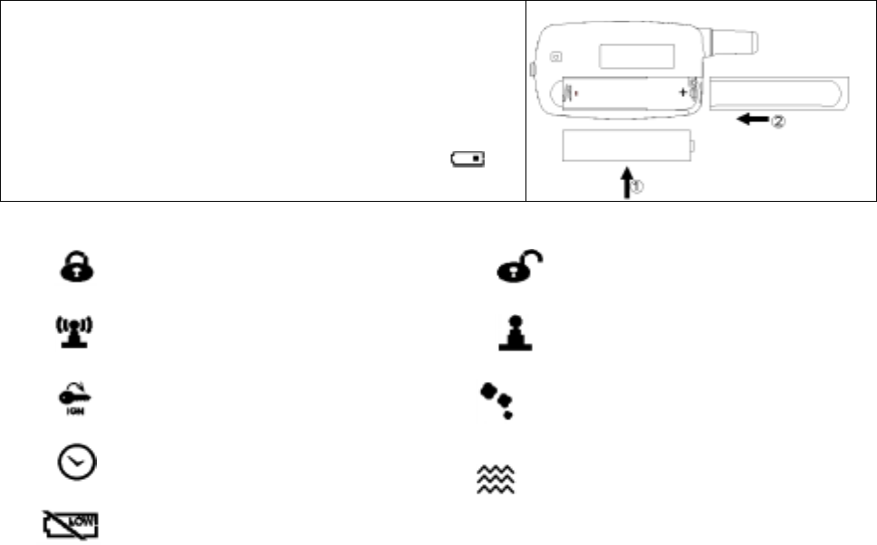
BATTERY REPLACEMENT:
A 1.5V type AAA Alkaline battery powers the Remote
Transceiver. When the power of the battery weakens a
icon shall be displayed on the LCD screen.
THE REMORE LCD ICONS WITH FUNCTION:
Door Lock
Your vehicle doors are locked
Door Unlock
Your vehicle doors are unlocked.
Remote Transmission
You are transmitting the signal to
control unit
In – Range Indicator
The system within the remote control
range.
Engine Starting
Your vehicle engine starting by
remote control
Engine Running
Your vehicle's engine is running
Timer Control Start
Engine start will automatically every
2 / 3-hour.
Vibration Mode
Remote Control vibrates when the
system is triggered
Low Battery
You have to replace the battery of
remote control.
This device complies with part 15 of the FCC rules. Operation is subject to the following two conditions.
1) This device may not cause harmful interference, and
2) This device must accept any interference received, including interference that may cause undesired
operation.
Per FCC 15.21, you are cautioned that changes or modifications not expressly approved by the part
responsible for compliance could void the user’s authority to operate the equipment.
deluxe 200 OP 4
“Operation is subject to the following two conditions: (1) this device may not cause
interference, and (2) this device must accept any interference, including
interference that may cause undesired operation of the device.”
This Class B digital apparatus complies with Canada RSS-210.
Cet appareil numérique de la classe B est conforme à la norme CNR-210 du
Canada
The abbreviation, IC, before the registration number signifies that registration was
performed based on a Declaration of Conformity indicating that Industry Canada
technical specifications were met. It does not imply that Industry Canada
approved the equipment. (DoC)
The term “IC:” before the certification/registration number only signifies that the
Industry Canada technical specifications were met.