Advance Security TR21 Car Alarm Transceiver User Manual
Advance Security Inc Car Alarm Transceiver
User Manual

1
TRX970
OPERATION MANUAL
2
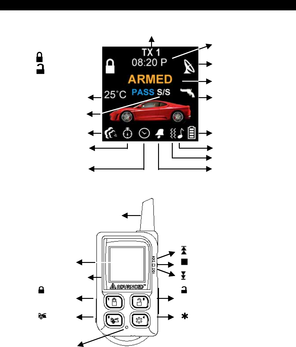
REMOTE TRANSCEIVER (TX)
A. OLED DISPLAY
I n case the remote transceiver malfunction,
errors or freeze of display, it is recommended
to reset your remote transceiver.
switch
OLED Displa
y
Engine Running
Name of Transmitter
switch
button
A
ntenna
switch
Button
Button 1
Button
Button 3
Button
Button 2
Button
Button 4
switch
button
A
ntenna
Reset Hole
Battery Level
Car Jacking
In – Range Indicator
Door Lock
Door Unlock
Alarm Status
Temperature
Engine Running
Melody Mode
Timer Start Alert Alarm
Count Down Timer
Parking Timer
Timer
Vibration Mode
Bypass Shock
Sensor (Zone 4)
3
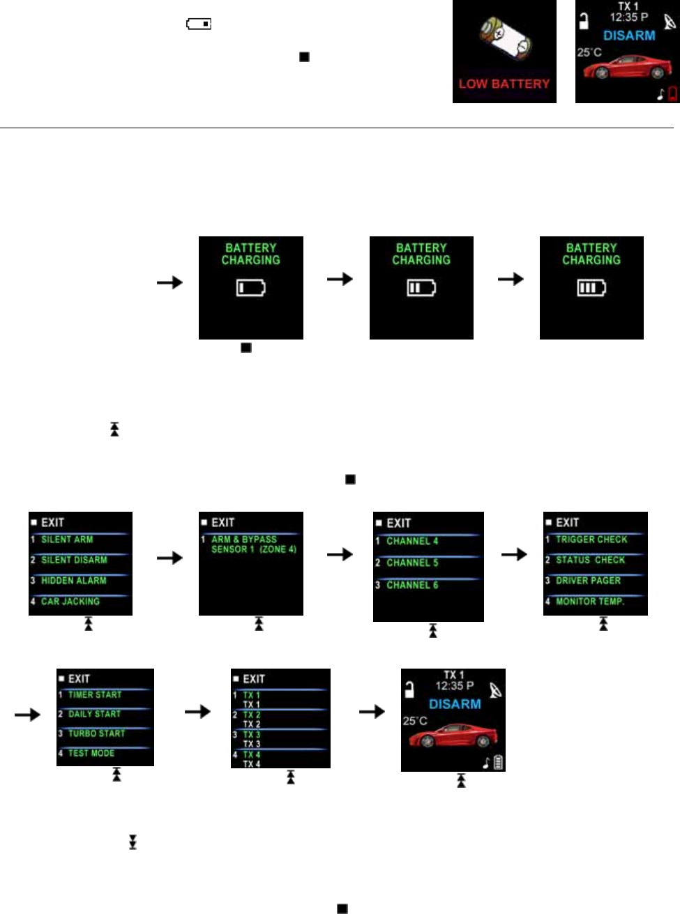
B. CHARGE THE BATTERY
Power by built-in 3.7V lithium polymer battery, if the OLED screen
display low battery or is flash, charge your remote
transceiver. While the battery of the Remote Transceiver is under
the battery charging, you can push the ” ” button to check
charging condition.
AC Power Supply
The remote transceiver equipped AC POWER SUPPLY /
AC ADAPTOR (Output Voltage: 4.2VDC – 5.5VDC and
with same USB plug), then you can charge the battery
indoors.
While the battery of
the Remote
Transceiver is under
charging.
Push the button; the
screen will display
Battery charging.
C. SELECT THE TRANSCEIVER’S BUTTON CONFIGURATION:
1. Spin up the Switch to select the transceiver button configuration you need and the OLED screen
will display the transceiver button configuration you select.
2. Within 5 seconds press the button 1, 2, 3 or 4 to remote control “button configuration” you selected.
Note: If 5 seconds of inactivity expired, or push the button, the transceiver button configuration mode
will exit.
Spin up the switch
to the page 1
Spin up the switch
to the page 2
Spin up the switch
to the page 3
Spin up the switch
to the page 4
Spin up the switch
to the page 5
Spin up the switch
to the page 6
Spin up the switch
resume to main page.
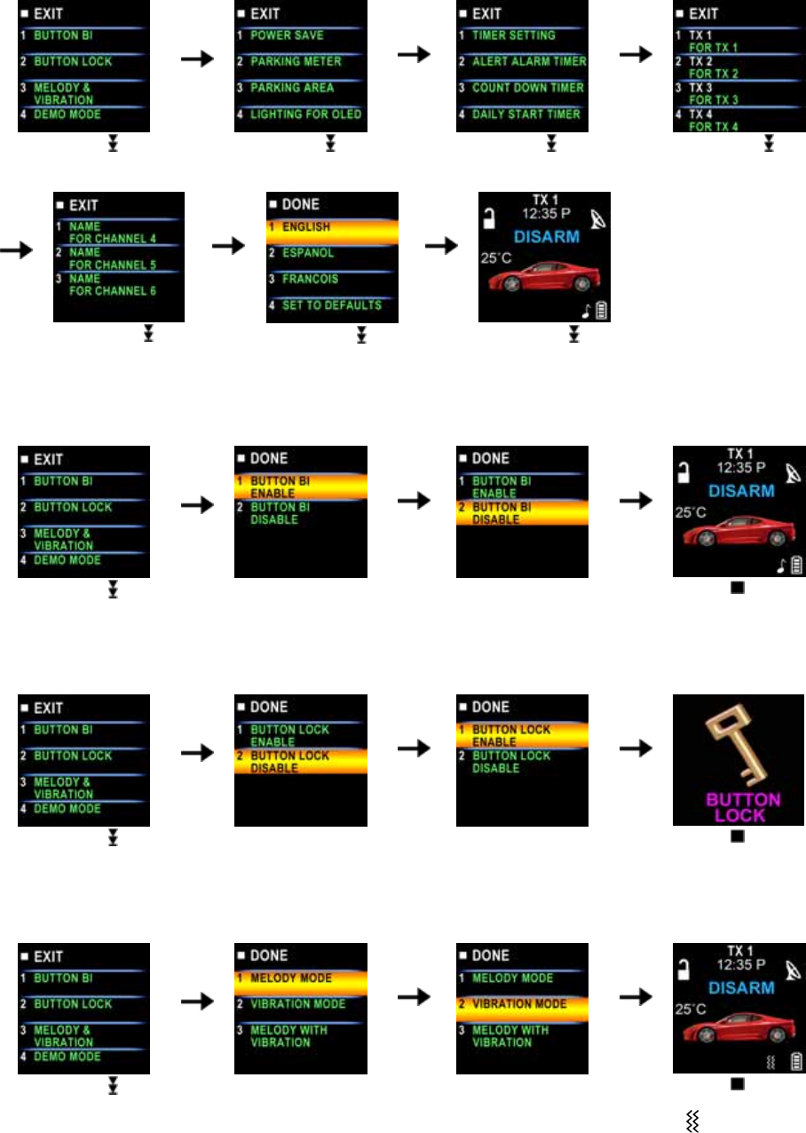
D. SELECT THE TRANSCEIVER FEATURES:
1. Spin down the Switch to select the transceiver feature you need and the OLED screen will display
the features you select.
2. Press the button 1, 2, 3 or 4 once within 3 seconds after finished selection and the OLED screen will
change the display alternatively.
Note: If 5 seconds of inactivity expire, or push the button, the transceiver features program mode will
exit.
4
Spin down the switch
to the page 1
Spin down the switch
to the page 2
Spin down the switch
to the page 3
Spin down the switch
to the page 4
Spin down the switch
to the page 5
Spin down the switch
to the page 6
Spin down the switch
resume to main page.
E- P1- 1. “BUTTON BI” SETTING: Example: Set the “Button Bi Disable”.
It has a short “bi” sound while pressing the button of the remote transceiver
Spin down the switch
to the page 1
Press the button 1 and it
will display previously
setting
Press the button 2 to
change the setting
Press the button and
the setting is done.
E- P1- 2. “BUTTON LOCK” SETTING: Example: Set the “Button Lock Enable”.
Spin down the switch
to the page 1
Press the button 2 and it
will display previously
setting
Press the button 1 to
change the setting
Press the button and
the setting is done.
E- P1- 3. “MELODY / VIBRATION MODE” SETTING: Example: set the Vibration mode.
Spin down the switch
to the page 1
Press the button 3 and it
will display previously
setting
Press the button 2 to
change the setting
Press the button and
the setting is done also
the icon will display
on the OLED screen
5
E- P1- 4. “DEMO MODE”:
Spin down the switch
to the page 1
Press the button 4 to
start Demo movie
Demo movie playing
Press the any Button to
exit.
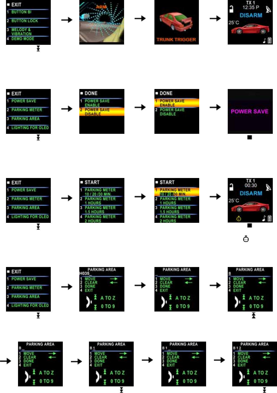
E- P2- 1. “POWER SAVE” SETTING: Example set the “Power Save Enable”.
While the power save mode, the LCD remote transceiver uses “0” current to save the battery power.
Spin down the switch
to the page 2
Press the button 1 and it
will display previously
setting.
Press the button 1 to
change the setting.
Press the button and
the setting is done.
E- P2- 2. “PARKING METER” SETTING: Example set the “Parking Meter 30 min..
Note: When “parking meter” trigger presses any button to stop the beeper.
Spin down the switch
to the page 2
Press the button 2
Press the button 1 three
times to set the parking
timer to 30 minutes.
Press the button to
start the parking meter
and the icon will
flash on the main page.
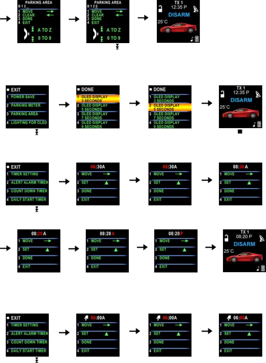
D- P2- 3. “PARKING AREA” SETTING: Example set the “Parking Area.” to “B120
Spin down the switch
to the page 2
Press the button 3, it will
display previously
parking area
Press the button 2 to
clear the parking area,
and the “-” flashes for
setting.
Spin up the switch to
setting the “B”
Press the button 1 and
the “-” flashes for
setting.
Spin down the switch
to set the “1”
Press the button 1 and
the “-” flashes for
setting.
Spin down the
switch to set the “2”.
6
Press the button 1 and
the “-” flashes for
setting.
Spin down the switch
to set the “0”.
Press the button 3 and
the setting is done.
D- P2- 4. “LIGHTING FOR OLED” TIMER SETTING: Example: set the OLED display from 2 seconds to 3
seconds.
Spin down the switch
to the page 2
Press the button 4 and it
will display previously
setting
Press the button 2 to
change the setting
Press the button and
the setting is done.
D- P3- 1. “TIMER” SETTING: Example set the timer to 08:20P
Spin down the switch
to the page 3
Press the button 1 and
the ”hour” digit flashes
for adjusting.
Press the button 2 to set
the ”hours” digit to “08”
Press the button 1 and
the ”minute” digit flashes
for adjusting.
Press the button 2 to
set the “minute” digit to
“20”
Press the button 1 and
the ”A” digit flashes for
adjusting.
Press the button 2 to
set the “P”
Press the button 3 and
the setting is done.
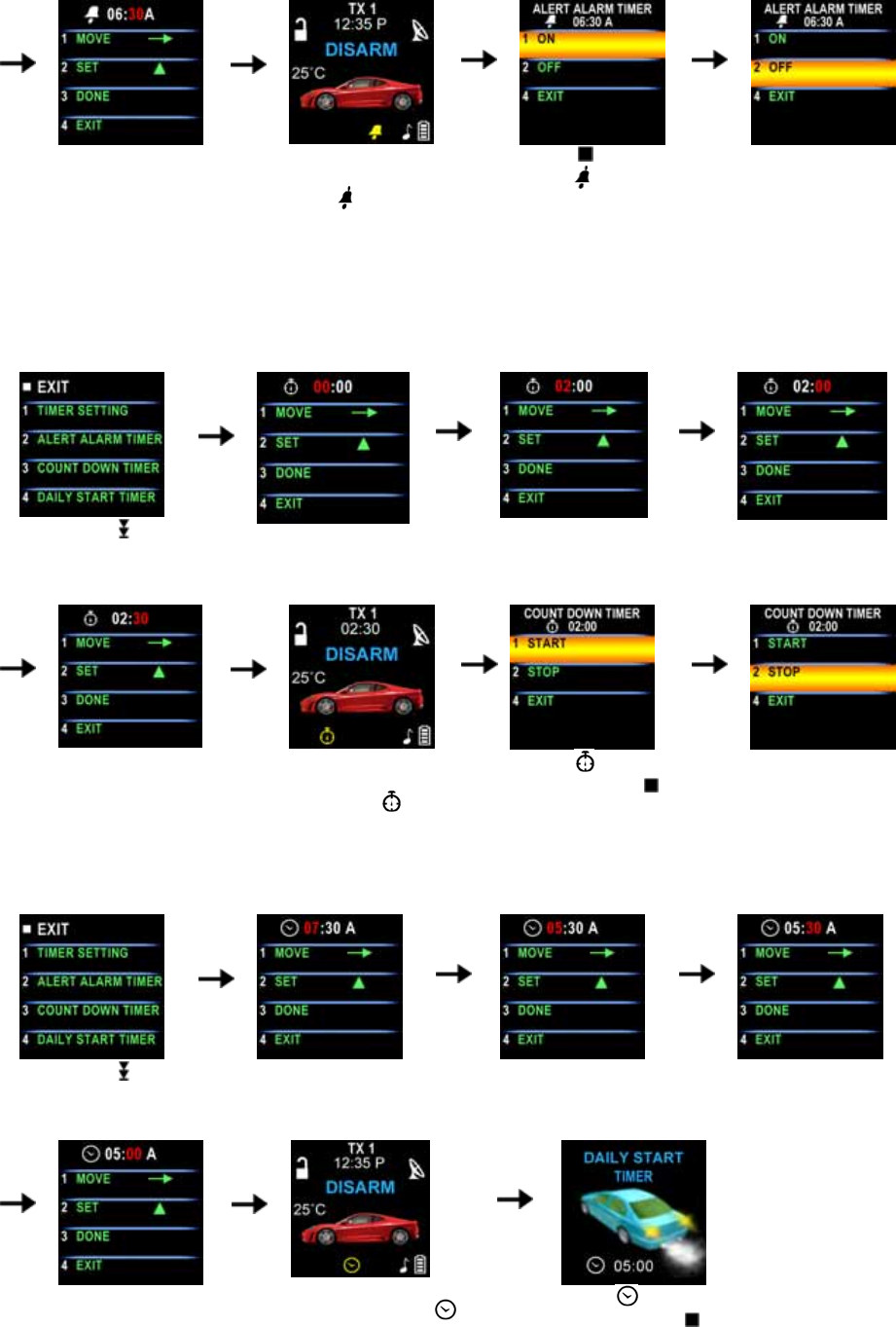
D- P3- 2. “ALERT ALARM TIMER” SETTING: Example set alert alarm timer to 06:30A
Note: When alert alarm timer trigger press any button to stop the beeper.
Spin down the switch
to the page 3
Press the button 2 and
the ”hour” digit flashes
for adjusting.
Press the button 2 to set
the ”hour” digit to “06”.
Press the button 1 and
the ”minute” digit flashes
for adjusting.
7
Press the button 2 to
set the ”minute” digit to
“30”.
Press the button 3 to
set the alert alarm timer
and the icon will
flash on the main page.
Push the button
While the icon is
flashing or When alert
alarm timer trigger, the
screen will display alert
alarm timer
Press the button 2 to
set off the alert alarm
timer or press any
button to stop alarm
while alert alarm timer
trigger
C- P3- 3. “COUNT DOWN TIMER” SETTING: Example set the count down timer to 2:30
Note: When count down timer is trigger, press any button to stop the beeper.
Spin down the switch
to the page 3
Press the button 3 and
the ”hour” digit flashes
for adjusting.
Press the button 2 to set
the ”hour” digit to “02”
Press the button 1 and
the ”minute” digit flashes
for adjusting.
Press the button 2 to
set the ”minute” digit to
“30”.
Press the button 3 to
start the count down
timer and the icon
will flash on the main
page.
While the icon is
flashing push the ” ”
button to display the
count down timer
Press the button 2 to
set off the count down
time.
C- P3- 4. “DAILY START TIMER” SETTING: Example set the Daily Start Timer to 05:00A
Spin down the switch
to the page 3
Press the button 4and
the ”hours” digit flashes
for adjusting.
Press the button 2 to set
the ”hours” digit to “05”.
Press the button 1 and
the ”minute” digit flashes
for adjusting.
Press the button 2 to
set the ”minute” digit to
“00”
Press the button 3 and the
setting is done. The
icon will flash on the main
page.
While the icon is
flashing push the ” ”
button to check the daily
start timer
8
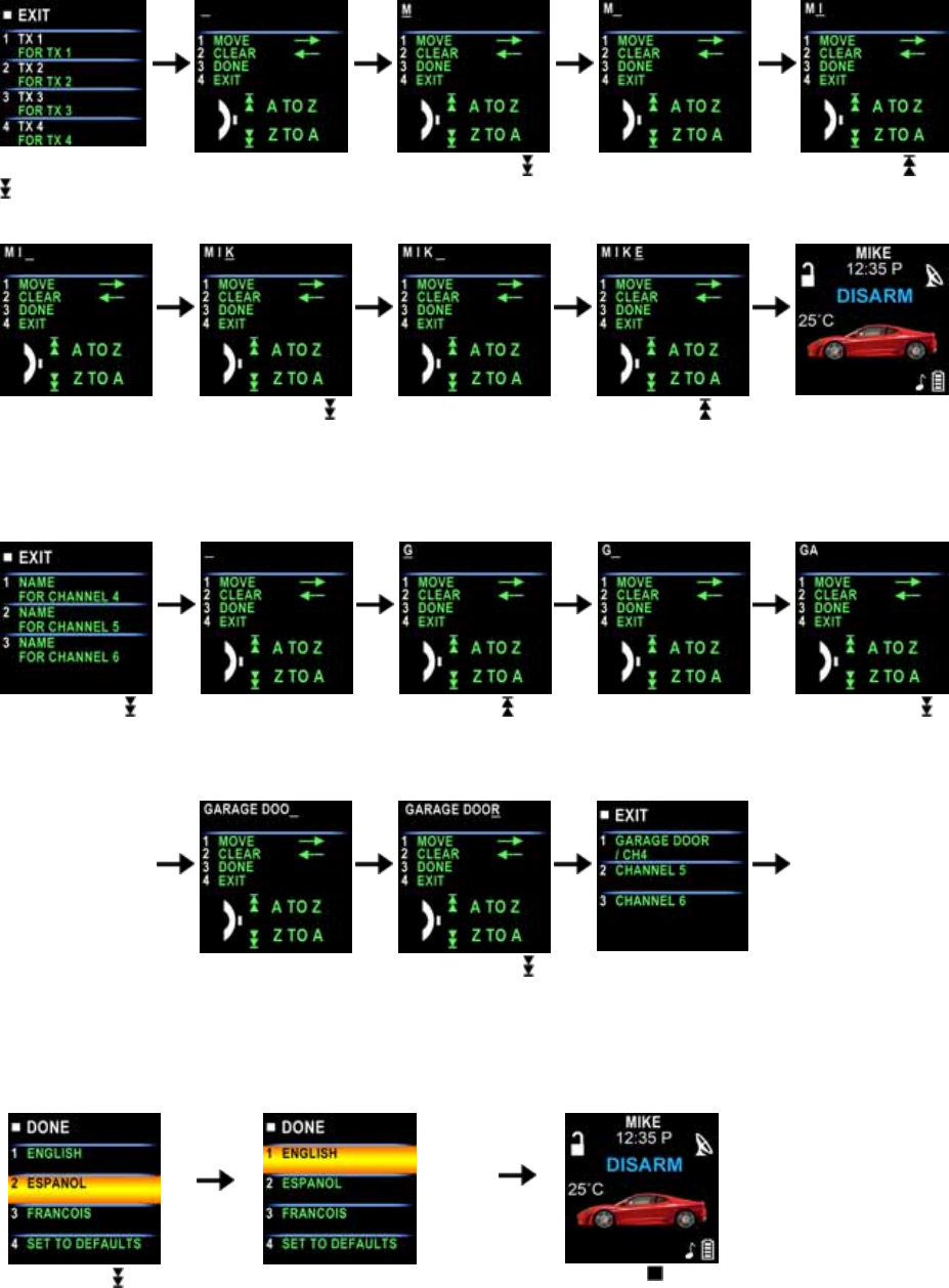
D- P4- 1. “NAME OF TX ” SETTING: Example Set Name of Transceiver 1 to MIKE
Spin down the
switch to the
page 4
Press the button1
and the “-” flashes
for setting.
Spin down the
switch to set the
“M”.
Press the button 1
and the “-” flashes
for setting.
Spin up the ”
switch to set
the ”I”.
Press the button 1
and the “-” flashes
for setting.
Spin down the
switch to set
the ”K”.
Press the button 1
and the “-” flashes
for setting.
Spin up the
switch to set
the ”E”.
Press the button 3
and the setting is
done.
D- P5- 1. “NAME OF CHANNEL ” SETTING: Example Set Name of channel 4 to GARAGE DOOR
Spin down the
switch to the page
5
Press the button 1
and the “-” flashes
for setting.
Spin up the
switch to set
the ”G”.
Press the button 1
and the “-” flashes
for setting.
Spin down the
switch to setting
the ”A”.
Following the
above step to
setting
Alphabetical to
GARAGE
DOOR
Press the button 1
and the “-” flashes
for setting.
Spin down the
switch to set
the ”R”
Press the button 3
and the setting is
done.
D- P6- 1. LANGUAGE SETTING: Example set the Language to English
Spin down the switch
to the page 6
Press the button 1 to set the
Language to ”ENGLISH”.
Press the button and
the setting is done.
9
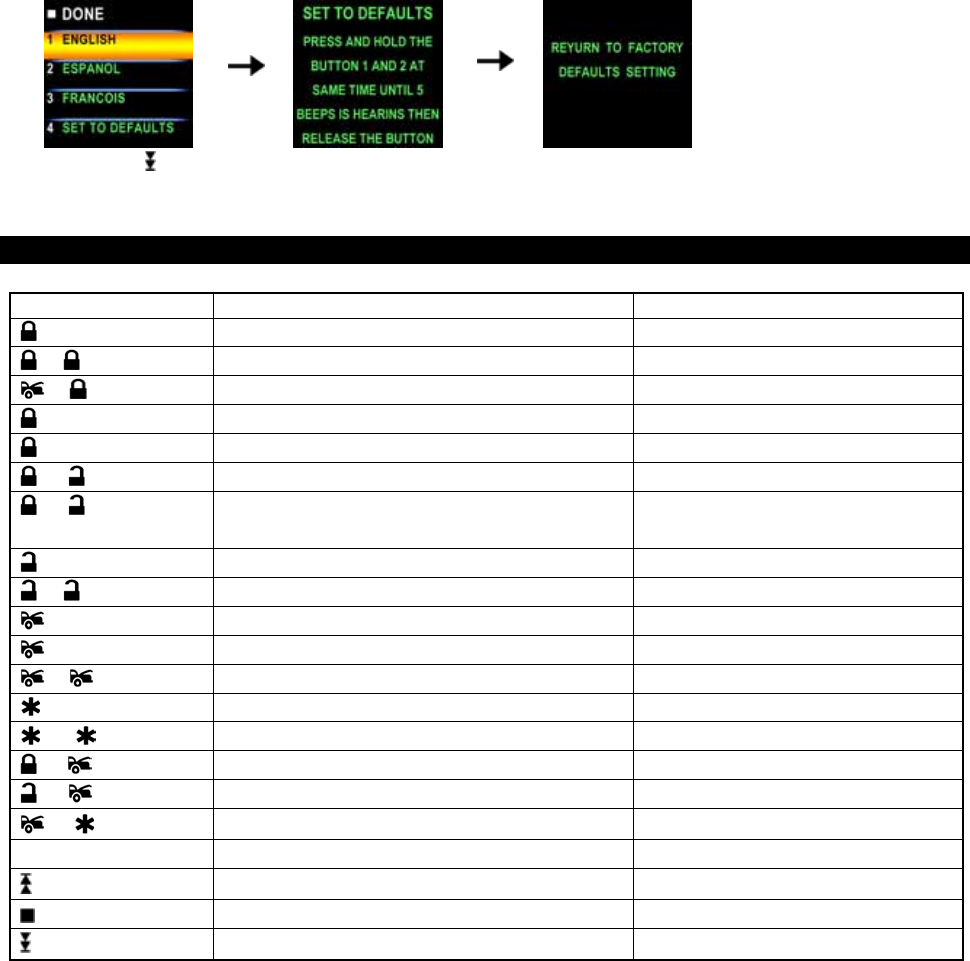
D- P6- 4. SET TO DEFAULTS:
Spin down the switch
to the page 6
Press the button 4.
Press the button 1 & 2
at same time to set the
defaults.
OPERATION:
A. REMOTE TRANSMITTER OPERATION:
Transmitter Button System Function Remark
1 Lock Doors & Arm System / Button 1
- Arm and Bypass The Zone 4. Press twice within 3 seconds
- Arm System and Hidden Alarm Function Press within 3 seconds
Car Locator Upon armed
(3-second) Panic function Press and Hold for 3 seconds.
+ Silent Arming / Disarming Ignition in "off" position.
+ (2-second) Active Anti Car-Jacking Mode Ignition in "on" position press and
hold for 2 seconds
2 Unlock Doors & Disarm System / Button 2
- Two Steps Door Unlock & Disarm System Press twice within 3 seconds.
3 Trunk Release
(2-second) Trunk Release (Channel 3) Press and Hold for 2 seconds
- Passive Arming By-pass While the system Disarmed.
4 Turn Off The Remote Start / Button 4 .
- Activate The Remote Start Press twice within 3 seconds.
+ Channel # 4 Timer Output
+ Channel # 5 Timer Output
+ Channel # 6 Timer Output
II Switching code For 2nd Car Operation. For regular remote transmitter
Button Function Selection For Two way Remote transceiver
Confirm Button / Back to Main Page For Two way Remote transceiver
Feature Selection For Two way Remote transceiver
This device complies with part 15 of the FCC rules. Operation is subject to the following two conditions.
(1)This device may not cause harmful interference, and
(2)This device must accept any interference received, including interference that may cause undesired operation.
Per FCC 15.21, you are cautioned that changes or modifications not expressly approved by the part responsible
for compliance could void the user’s authority to operate the equipment.
This equipment has been tested and found to comply with the limits for a Class B digital device, pursuant to
Part 15 of the FCC Rules. These limits are designed to provide reasonable protection against harmful
interference in a residential installation. This equipment generates, uses and can radiate radio frequency
energy and, if not installed and used in accordance with the instructions, may cause harmful interference to
radio communications. However, there is no guarantee that interference will not occur in a particular
installation. If this equipment does cause harmful interference to radio or television reception, which can be
determined by turning the equipment off and on, the user is encouraged to try to correct the interference by one
or more of the following measures:
-Reorient or relocate the receiving antenna.
-Increase the separation between the equipment and receiver.
-Connect the equipment into an outlet on a circuit different from that to which the receiver is connected.
-Consult the dealer or an experienced radio/TV technician for help.