Advance Security TR23 Remote Control User Manual MODEL 6876
Advance Security Inc Remote Control MODEL 6876
Users Manual
MODEL XRO-9100
REMOTE ENGINE STARTER
WITH ALARM SYSTEM
OWNER’S MANUAL
1
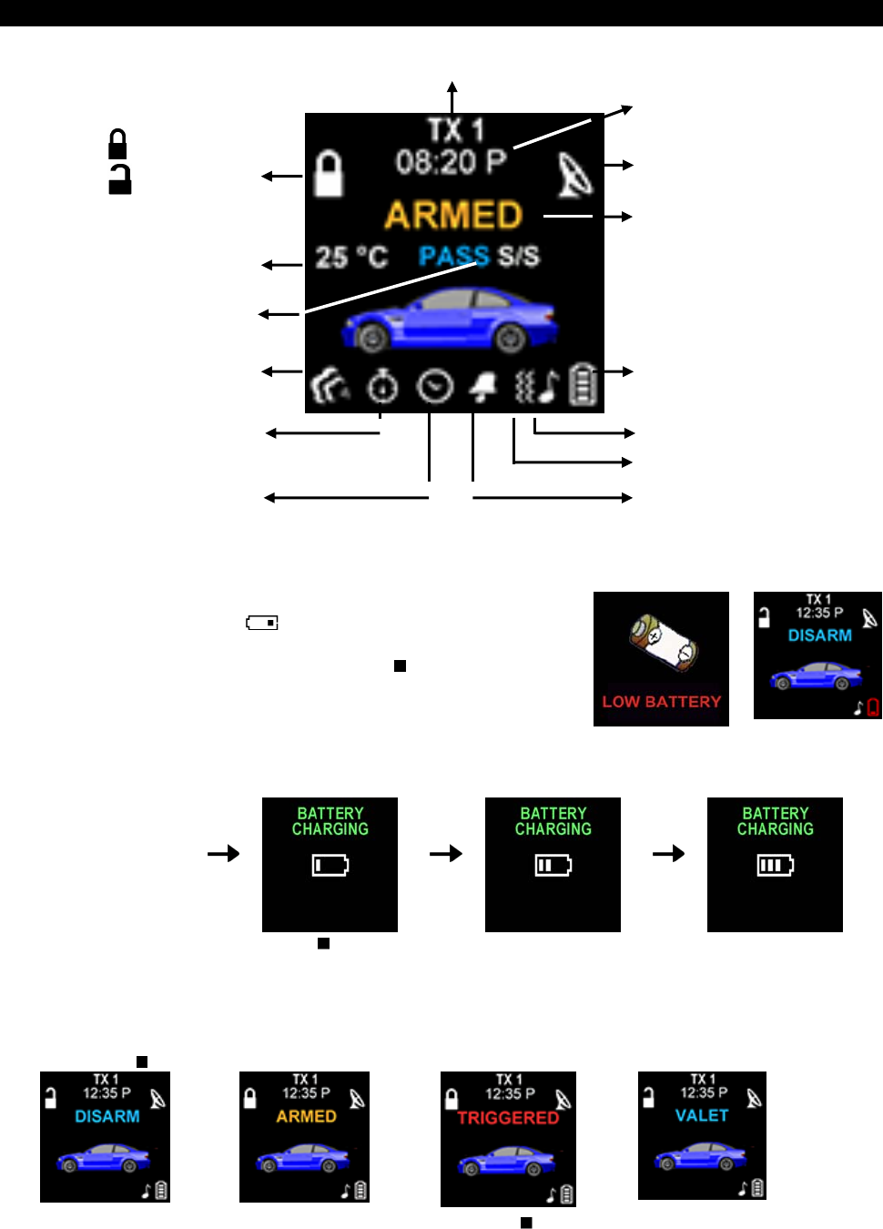
REMOTE TRANSCEIVER (TX)
A. OLED DISPLAY Name of Transmitter
Timer
Door Lock
Door Unlock
In – Range Indicator
Alarm Status
Temperature
Bypass Shock
Sensor
Battery Level
Engine Running
Melody Mode
Count Down Timer
Parking Timer
Vibration Mode
Alert Alarm
Timer Start
B. CHARGE THE BATTERY
Power by built-in 3.7V lithium polymer battery, if the OLED screen
display low battery or is flash, charge your remote
transceiver. While the battery of the Remote Transceiver is under
the battery charging, you can push the ” ” button to check
charging condition.
While the battery of
the Remote
Transceiver is under
charging.
Push the button; the
screen will display
Battery charging.
C. MAIN PAGE:
1. Press the button, the screen will display main page.
2. While the icon flashing on the OLED screen, press the button, the OLED screen will display the
detail of the flash icon, the display sequence of flash icon as follows: TRIGGERED / ENGINE
RUNNING / COUNT DOWN TIMER / TIMER START / ALART TIMER condition.
2
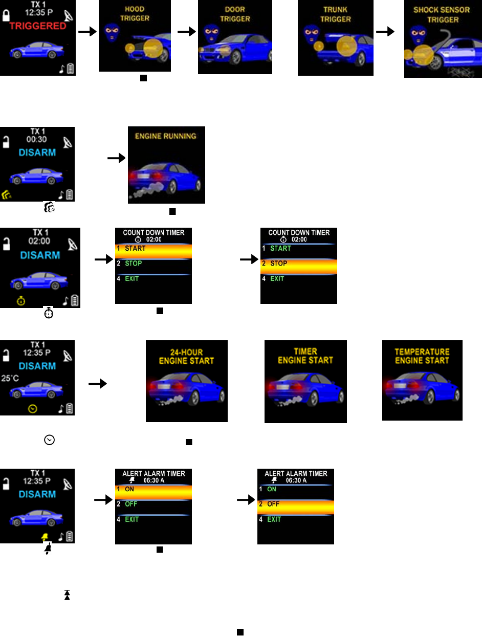
While the
TRIGGERED icon
flash.
Push the
button to display
triggered area.
While the icon flash
Push the button
While the icon
flash
Push the button, the count
down timer will display.
Press the button 2to set off
the count down time
missing
graphic
or
Or
While the icon flash Push the button, the OLED screen will display individually i.e. daily start timer,
timer start or temperature start, depend on which you selected.
While the icon
flash
Push the button, the alert
alarm time will display.
Press the button 2 to set off
the alert alarm timer
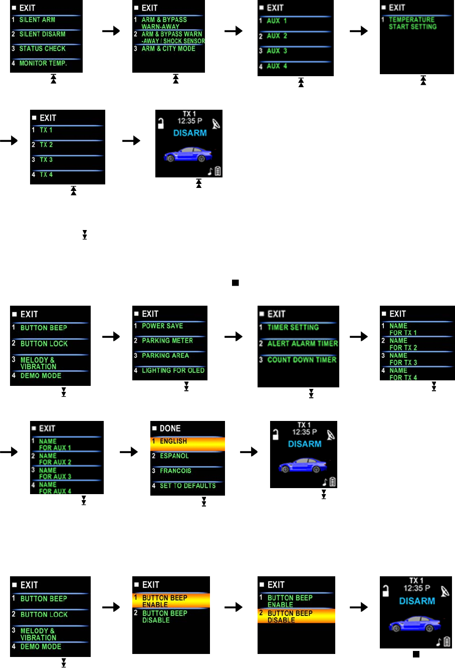
D. SELECT THE TRANSCEIVER’S BUTTON CONFIGURATION:
1. Spin up the Switch to select the transceiver button configuration you need and the OLED screen
will display the transceiver button configuration you select.
2. Within 5 seconds press the button 1, 2, 3 or 4 to remote control “button configuration” you selected.
Note: If 5 seconds of inactivity expired, or push the button, the transceiver button configuration mode
will exit.
3
Spin up the switch
to the page 1
Spin up the switch
to the page 2
Spin up the switch
to the page 3
Spin up the switch
to the page 4
Spin up the switch
to the page 5
Spin up the switch
resume to main page.
E. SELECT THE TRANSCEIVER FEATURES:
1. Spin down the Switch to select the transceiver feature you need and the OLED screen will display
the features you select.
2. Press the button 1, 2, 3 or 4 once within 3 seconds after finished selection and the OLED screen will
change the display alternatively.
Note: If 5 seconds of inactivity expire, or push the button, the transceiver features program mode will
exit.
Spin down the switch
to the page 1
Spin down the switch
to the page 2
Spin down the switch
to the page 3
Spin down the switch
to the page 4
Spin down the switch
to the page 5
Spin down the switch
to the page 6
Spin down the switch
resume to main page.
E- P1- 1. “BUTTON BI” SETTING: Example: Set the “Button Bi Disable”.
It has a short “bi” sound while pressing the b
utton of the remote transceiver
Spin down the switch
to the page 1
Press the button 1 and it
will display previously
setting
Press the button 2 to
change the setting
Press the button and
the setting is done.
4
E- P1- 2. “BUTTON LOCK” SETTING: Example: Set the “Button Lock Enable”.
Spin down the switch
to the page 1
Press the button 2 and it
will display previously
setting
Press the button 1 to
change the setting
Press the button and
the setting is done.
D- P1- 3. “MELODY / VIBRATION MODE” SETTING: Example: set the Vibration mode.
Spin down the switch
to the page 1
Press the button 3 and it
will display previously
setting
Press the button 2 to
change the setting
Press the button and
the setting is done also
the icon will display
on the OLED screen
E- P1- 4. “DEMO MODE”:
Spin down the switch
to the page 1
Press the button 4 to
start Demo movie
Demo movie playing
Press the any Button to
exit.
E- P2- 1. “POWER SAVE” SETTING: Example set the “Power Save Enable”.
While the power save mode, the LCD remote transceiver uses “0” current to save the battery power.
Spin down the switch
to the page 2
Press the button 1 and it
will display previously
setting.
Press the button 1 to
change the setting.
Press the button and
the setting is done.
E- P2- 2. “PARKING METER” SETTING: Example set the “Parking Meter 30 min..
Note: When “parking meter” trigger presses any button to stop the beeper.
Spin down the switch
to the page 2
Press the button 2
Press the button 1 three
times to set the parking
timer to 30 minutes.
Press the button to
start the parking meter
and the icon will
5
flash on the main page.
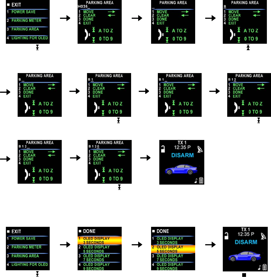
D
- P2- 3. “PARKING AREA” SETTING: Example set the “Parking Area.” to “B120
Spin down the switch
to the page 2
Press the button 3, it will
display previously
parking area
Press the button 2 to
clear the parking area,
and the “-” flashes for
setting.
Spin up the switch to
setting the “B”
Press the button 1 and
the “-” flashes for
setting.
Spin down the switch
to set the “1”
Press the button 1 and
the “-” flashes for
setting.
Spin down the
switch to set the “2”.
Press the button 1 and
the “-” flashes for
setting.
Spin down the switch
to set the “0”.
Press the button 3 and
the setting is done.
D- P2- 4. “LIGHTING FOR OLED” TIMER SETTING: Example: set the LCD display from 2 seconds to 3
seconds.
Spin down the switch
to the page 2
Press the button 4 and it
will display previously
setting
Press the button 2 to
change the setting
Press the button and
the setting is done.
D- P3- 1. “TIMER” SETTING: E
xample set the timer to 08:20P
6
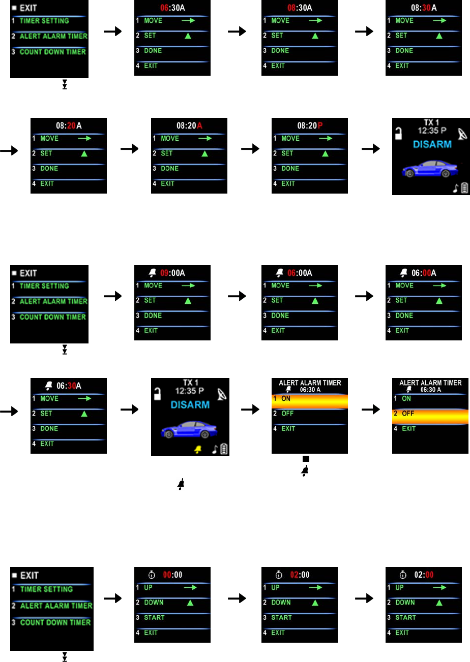
Press the button 2 to set
the ”hours” digit to “08”
Press the button 1 and
the ”minute” digit flashes
for adjusting.
Spin down the switch
to the page 3
Press the button 1 and
the ”hour” digit flashes
for adjusting.
Press the button 2 to
set the “minute” digit to
“20”
Press the button 1 and
the ”A” digit flashes for
adjusting.
Press the button 2 to
set the “P”
Press the button 3 and
the setting is done.
D- P3- 2. “ALERT ALARM TIMER” SETTING: Example set alert alarm timer to 06:30A
Note: When alert alarm timer trigger press any button to stop the beeper.
Spin down the switch
to the page 3
Press the button 2 and
the ”hour” digit flashes
for adjusting.
Press the button 2 to set
the ”hour” digit to “06”.
Press the button 1 and
the ”minute” digit flashes
for adjusting.
Press the button 2 to
set the ”minute” digit to
“30”.
Press the button 3 to
set the alert alarm timer
and the icon will
flash on the main page.
Push the button
While the icon is
flashing or When alert
alarm timer trigger, the
screen will display alert
alarm timer
Press the button 2 to
set off the alert alarm
timer or press any
button to stop alarm
while alert alarm timer
trigger
C- P3- 3. “COUNT DOWN TIMER” SETTING: Example set the count down timer to 2:30
Note: When count down timer is trigger, press any button to stop the beeper.
Spin down the switch
to the page 3
Press the button 3 and
the ”hour” digit flashes
for adjusting.
Press the button 2 to set
the ”hour” digit to “02”
Press the button 1 and
the ”minute” digit flashes
for adjusting.
7
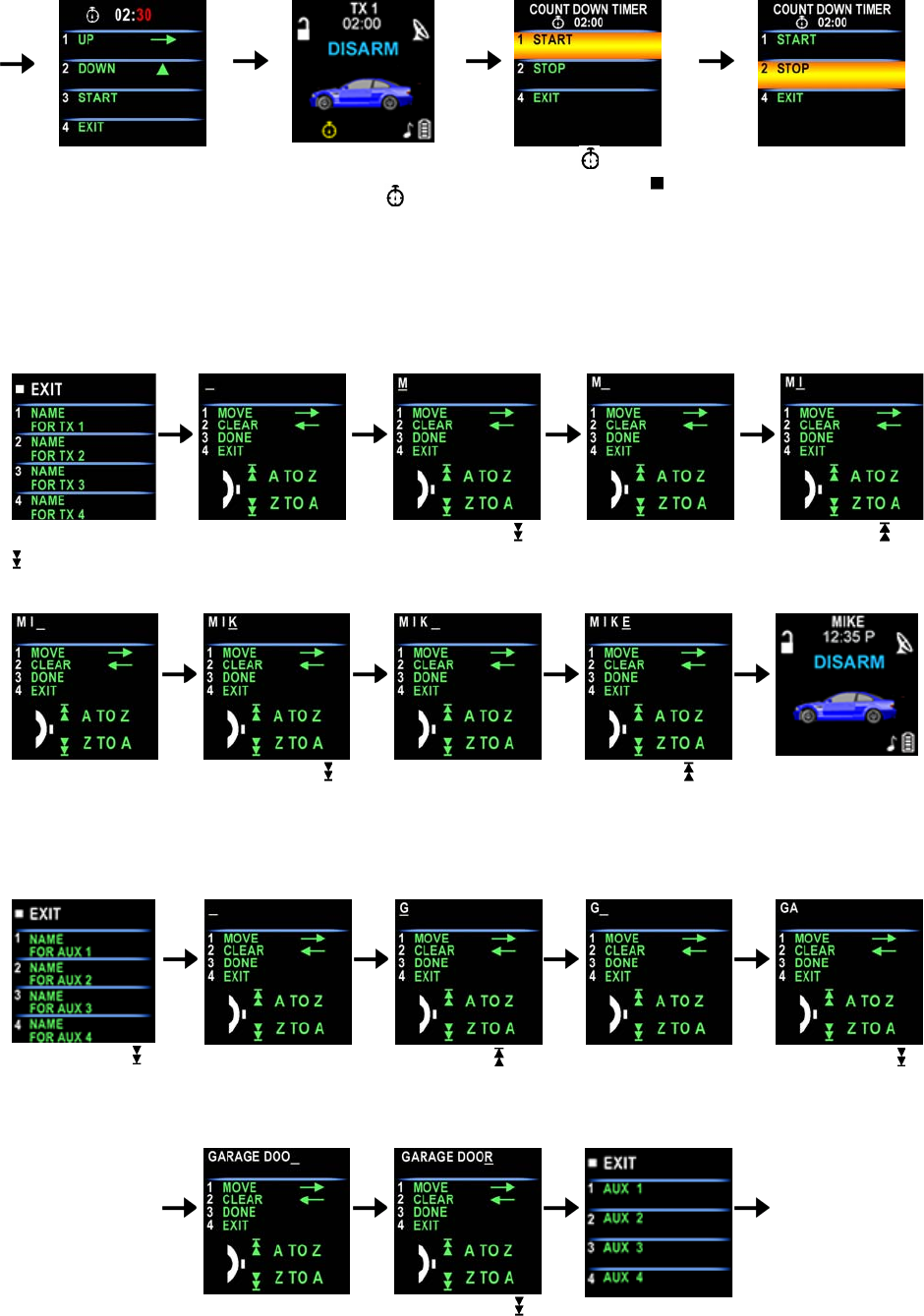
Press the button 2 to
set the ”minute” digit to
“30”.
Press the button 3 to
start the count down
timer and the icon
will flash on the main
page.
While the icon is
flashing push the ” ”
button to display the
count down timer
Press the button 2 to
set off the count down
time.
D- P4- 1. “NAME OF TX ” SETTING: Example Set Name of Transceiver 1 to MIKE
Spin down the
switch to the
page 4
Press the button1
and the “-” flashes
for setting.
Spin down the
switch to set the
“M”.
Press the button 1
and the “-” flashes
for setting.
Spin up the ”
switch to set
the ”I”.
Press the button 1
and the “-” flashes
for setting.
Spin down the
switch to set
the ”K”.
Press the button 1
and the “-” flashes
for setting.
Spin up the
switch to set
the ”E”.
Press the button 3
and the setting is
done.
D- P5- 1. “NA
ME OF CHANNEL ” SETTING: Example Set Name of channel 4 to GARAGE DOOR
Spin down the
switch to the page
5
Press the button 1
and the “-” flashes
for setting.
Spin up the
switch to set
the ”G”.
Press the button 1
and the “-” flashes
for setting.
Spin down the
switch to setting
the ”A”.
Following the
above step to
setting
Alphabetical to
RAGE DOO
Press the button 1
and the “-” flashes
for setting.
Spin down the
switch to set
the ”R”
Press the button 3
and the setting is
done.
8
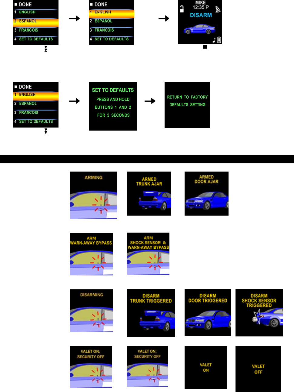
D- P6- 1. LANGUAGE SETTING: Example set the Language to English
Spin down the switch
to the page 6
Press the button 1 to set the
Language to ”ENGLISH”.
Press the button and
the setting is done.
D- P6- 4. SET TO DEFAULTS:
Spin down the switch
to the page 6
Press the button 4.
Press the button 1 & 2
at same time to set the
defaults.
OPERATION:
ARMING
DISARMING
VALET MODE
9
CAR LOCATOR
PANIC
FUNCTION
TRIGGER THE
SYSTEM
SINGLE
TRIGGER
MULTI
TRIGGER
ANTI CAR-
JACKING
FORM POSSE
PORT
DRIVER
PAGING
TRUNK
RELEASE
OUT OF
RANGE
TEMPERATURE
CHECK
10
MULTI-
VEHICLE
SECURITY
OPREATION
TURBO TIMER
MODE
REMOTE
START
TIMER START
TEMPERATURE
START
DAILY TIMER
START
TURN OFF THE
REMOTE
START
11

Model XRO-9100
SELECTABLE FEATURES
The selectable features can be set manually as explained below,
Factory default settings are indicated by bold text.
Note : The method of manual override can either be selected to operate from the valet switch or operate as
custom code.
Be certain to place a check mark indicating the method used in the box located on the last page of the
owner’s manual.
NOTE: Keyless Entry Models with no horn output will Flash the Parking Lights instead of chirp where chirp is
indicated.
RF Programmable Feature Bank 1 Is For Transmitter Programming See Transmitter Programming
Guide.
RF Programmable Features Bank 2 Is Alarm Selectable Features:
Feature
Selection 1 Chirp 2 Chirps 3 Chirps 4 Chirps 5 Chirps 6 Chirps
1st Door L/UL 1 Sec. 3.5 Sec. 1 Sec L,
Dbl.U/L Dbl L, 1 Sec
UL Dbl L, Dbl UL 1 Sl/350ms
UL
2nd Accy Lock Auto Lock On Auto Lock
Off
3rd Accy. Ul Auto UL Dr. Auto UL ALL Auto UL Off
4th Headlights On Arm On Disarm On Both Off
5th Passive
Locks Passive Active
6th Pass/Act Arm Passive Arm Actime Arm
7th Siren/Horn Siren/Horn Siren Only Horn Only
8th Horn Chirp 10 ms 16 ms 30 ms 40 ms 50 ms
9th O/R Method Custom Code Valet
10th 2 Step U/L On Arm Off
11th Chp Del Tx On Arm Off
12th
Volts/HdWire Not Available
13th Trigger
Circuits Not Available
14th L/UL Poll Not Available
To exit program mode, turn ignition off, or press and release valet
switch.
RF Programmable Features Bank 3 Is Remote Start Selectable Features :
Feature Selection 1 Chirp 2 Chirps 3 Chirps 4 Chirps 5 Chirps 6 Chirps
1st Defrost Output Pulsed 10 Mins
2nd RF Start Chirp Off On
3rd Run Time 5 Mins 10 Mins 15 Mins 20 Mins
4th Parking Lights On Steady Flashing
5th Input Check Voltage Tach DBI Tach
6th Voltage Level >0.5V B4
Start <0.5V B4
Start
7th Ing. 2 Select Off During
Crank On During
Crank Same Aas
Accy.
12
8th Ign. 3 Select Off During
Crank On During
Crank Same Aas
Accy.
9th Diagnostics Off On
10th Crank Time 0.8 Sec 1.0 Sec 1.5 Sec 2.0 Sec
11th Gas / Diesel Gas Diesel 10 Diesel 15 Diesel 20 DBI
12th Transponder
O/P While R/S On During Start Until Ign. Off
13th Temp Start Off On
14th Crank
Averaging Averaging Preset Time (NOTE:When Averaging, the engine must be started 4 times
with the key to be effective)
15th R/S Shock Shunt Until
Clear Shunt R/S
Cycle Shunt From
TX
16th Turbo Select Off 3 Mins 5 Mins 10 Mins
17th Black /Blue
(Aux O/P) Single Pulse As Feature #1
Note : Once you enter the feature programming mode, do not allow more than 15 seconds to pass between
steps or the programming will be terminated.
Chirp Function Parking light Function
1 chirp Arm 1 flash Arm
2 chirps Disarm 2 flashes Disarm
3 chirps Arm/ Door opened 3 flashes Disarm / Intrusion
4 chirps Disarm / Intrusion Constant On * Under Remote Start *
LED Function LED Function
Off Disarmed 1 flash... pause Zone 1 /
Slow Flash Armed 2 flash... pause Zone 2 /
Rapid
Flashing PassiveArming/ Active
Rearming 3 flash… pause Zone 3 /
On (Solid) Valet Mode
* Depend on programming feature select
Transmitter Button System Function Remark
Lock Doors & Arm System / Button
- Defeat the Pre-detect stage of s/s
- - Defeat the Pre-detect and full detect stages
of s/s
- - - City Mode
or
(3-second)
Activate Panic function Press and Hold for 3 sec.
or
(3-second)
Stop Panic function Press and Hold for 3 sec.
(2-second) Silent Arming Activate during programming
(2-second) Silent Disarming
Unlock Doors & Disarm System / Button 2
- Two Steps Door Unlock & Disarm System Press twice within 3 sec.
Trunk Release Press and Hold for 2 sec
- Turn Off Remote Start Press twice within 2 sec.
- Turn On Remote Start Press twice within 2 sec.
Channel 1
13

+ Channel 2
+ Channel 3
+ Channel 4
2-WAY OLED REMOTE CONTR TRANSCEIVER OPERATION ONLY
Button Function Selection For Two way Remote transceiver
Confirm Button / Back to Main Page For Two way Remote transceiver
Feature Selection For Two way Remote transceiver
14
Federal Communication Commission Interference Statement
This equipment has been tested and found to comply with the limits for a Class B
digital device, pursuant to Part 15 of the FCC Rules. These limits are designed to
provide reasonable protection against harmful interference in a residential installation.
This equipment generates, uses and can radiate radio frequency energy and, if not
installed and used in accordance with the instructions, may cause harmful interference
to radio communications. However, there is no guarantee that interference will not
occur in a particular installation. If this equipment does cause harmful interference to
radio or television reception, which can be determined by turning the equipment off
and on, the user is encouraged to try to correct the interference by one of the
following measures:
. Reorient or relocate the receiving antenna.
. Increase the separation between the equipment and receiver.
. Connect the equipment into an outlet on a circuit different from that to which the
receiver is connected.
. Consult the dealer or an experienced radio/TV technician for help.
FCC Caution :To assure continued compliance, any changes or modifications not
expressly approved by the party responsible for compliance could void the user's
authority to operate this equipment. (Example - use only shielded interface cables
when connecting to computer or peripheral devices).
FCC Radiation Exposure Statement
This device complies with Part 15 of the FCC Rules. Operation is subject to the
following two conditions:
(1) This device may not cause harmful interference, and (2) This device must accept
any interference received, including interference that may cause undesired
operation.
To satisfy FCC RF exposure compliance requirements, this device should be used in
hand-held, hand-operated configurations only. The device and its antenna must
maintain a separation distance of 20cm or more from a person’s body, except for the
hand and wrists, to satisfy RF exposure compliance.
This device is designed to be used in a person’s hands and its operating configurations
do not support normal transmissions while it is carried in pockets or holsters next tot a
person’s body.