Advance Security TR32 Remote Control User Manual 090702 C3 RS1100
Advance Security Inc Remote Control 090702 C3 RS1100
UserManual.wiki
>
Advance Security
>
TR32 User Manual
Users Manual
Navigation menu
Upload a User Manual
Namespaces
Wiki Guide
HTML
PDF
Info
Views
User Manual
Discussion / Help
Navigation
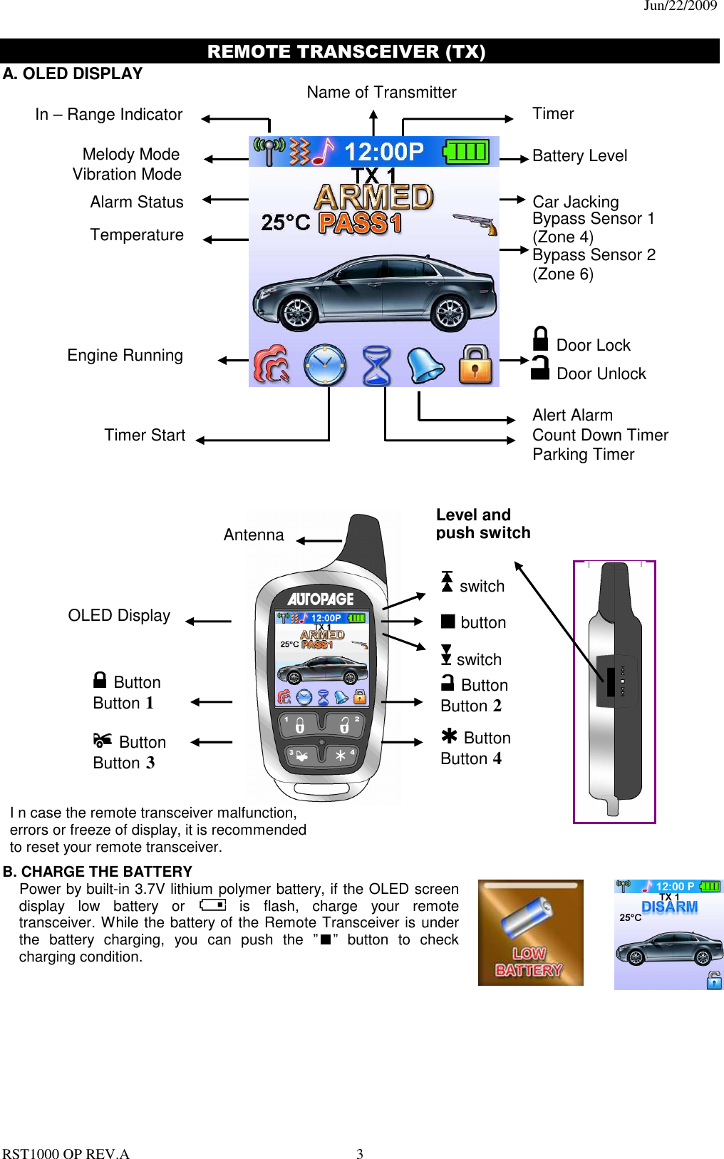
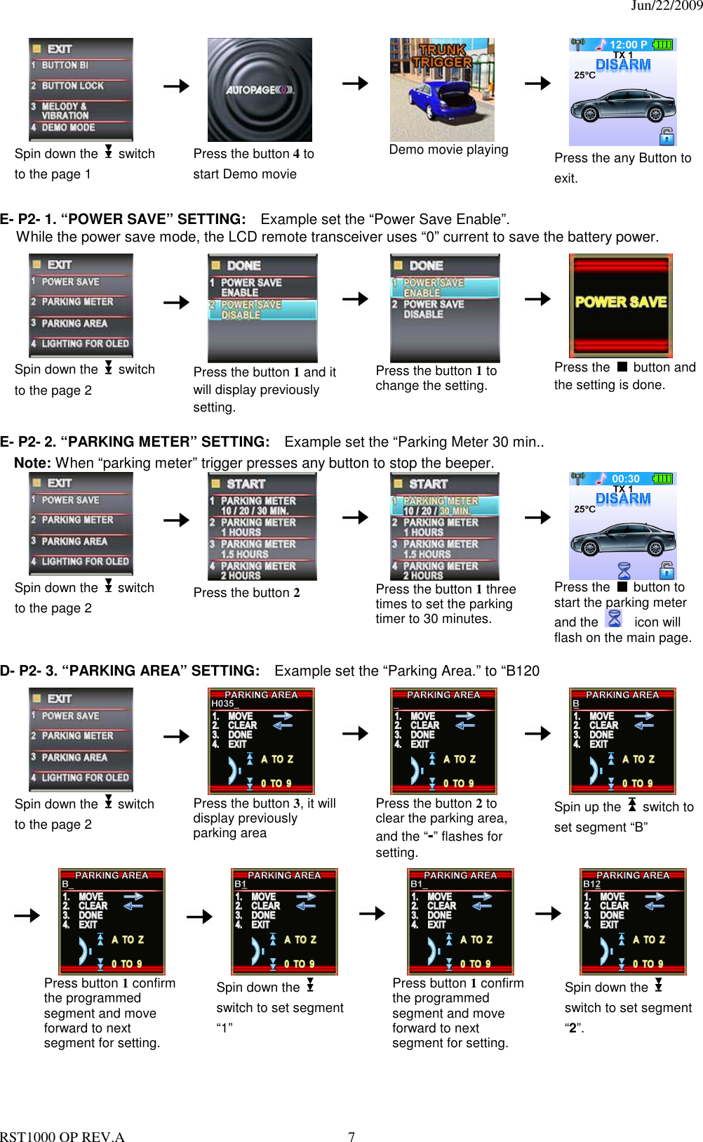
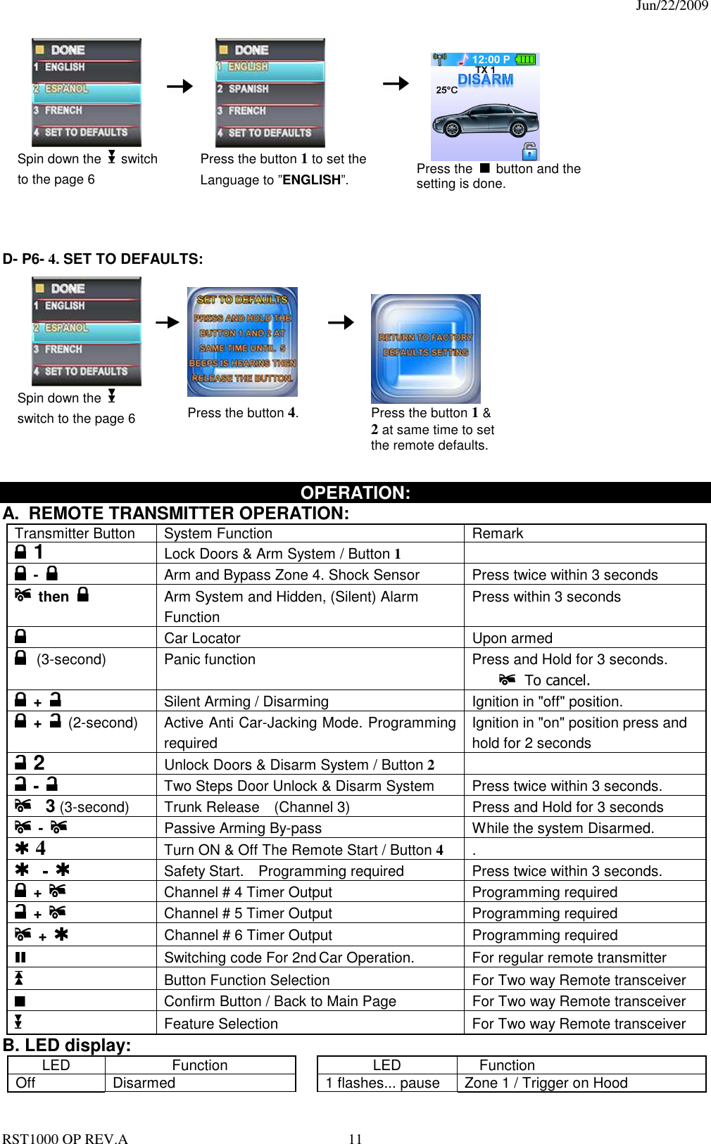
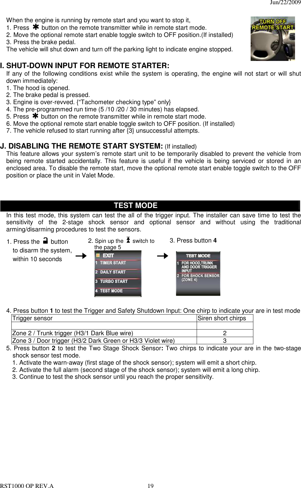
![Jun/22/2009 RST1000 OP REV.A 12 Slow Flash Armed 2 flashes... pause Zone 2 / Trigger on Trunk Fast Flash Passive Arming 3 flashes... pause Zone 3 / Trigger on Door Switch On (Solid) Valet Mode 4 flashes... pause Zone 4 / Trigger on Shock Sensor Pause On Password Lock-Out 5 flashes... pause Zone 5 / Trigger on Ignition Switch C. CHIRP INDICATORS: D. PARKING LIGHT: Chirp Function Parking light Function 1 chirp Arm 1 flash Arm 2 chirps Disarm 2 flashes Disarm 3 chirps Ajar Warning 3 flashes Disarm / Triggered 4 chirps Disarm / Triggered 12 flashes Car Locator 6 chirps Car Locator Constant On Under Remote Start E. ACTIVE ARMING – LOCK & ARM: 1. Press the button on the transmitter. 2. The siren will chirp once and parking light will flash once indicating that the system is now armed. The vehicle door will lock upon arming when interfaced with the security system. AJAR WARNING: If the siren sounds 3 chirps, then you have left a door, trunk, or hood lid ajar. SILENT ARMING: Spin up the switch to the page 1 and then press the “Silent Arm” button or press the transmitter and buttons at the same time to arm your security system, No chirp sound will be heard, arm confirmation will be through the vehicles parking lights only. SENSOR BY-PASS: Bypass The Zone 4: Spin up the switch to the page 2 and then press the button 1 or press the button on the transmitter two times within 3 seconds. This will arm the security system and by-pass the zone 4-shock sensor. The system will chirp one additional time to confirm the sensor bypass mode was activated. The sensor bypass feature is programmed to activate for one arming cycle only. The security system will return to normal operation during the next arming cycle. HIDDEN ALARM FUNCTION (Silent Alarm): Spin up the switch to the page 1 and then press the “Hidden Alarm” button or press the button first; within 3 seconds press the button to activate the hidden alarm function. The security system will arm and with “Hidden Alarm Function” The siren / horn will be silenced even if the unit is triggered in the armed status. Notification will only be through the hand held two-way remote. F. PASSIVE ARMING (Programming Required) Active arming / disarming is controlling your security system via the remote transmitter. This security system is equipped with an optional Passive Arming feature which allows the security system to arm 30 seconds after the last door is closed. Operation is as follows. 1. Turn the ignition to the “OFF” position and exit the vehicle. 2. After all entrances are closed, the security system LED will flash fast for 30 seconds. If you reopen any door / hood / trunk, the security system LED will stop flashing. It will begin flashing again once all of the vehicle entrances are closed. 3. After 30-second timer has elapsed, the security system will automatically “ARM”. The siren will chirp [1] time and the parking lights will flash [1] time. PASSIVE ARMING WITH PASSIVE DOOR LOCKING: The vehicle doors will automatically lock after passive arming cycle has been completed. PASSIVE ARMING BY-PASS: While the system disarmed, Press the button twice, the security will respond with [1] chirp and LED will turn “ON”. The security system will remain in this temporary state for as](https://usermanual.wiki/Advance-Security/TR32/User-Guide-1143850-Page-12.png)
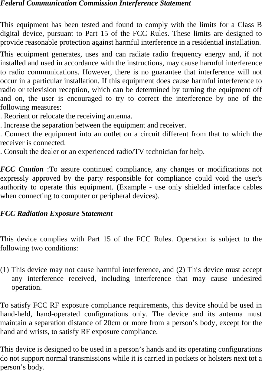
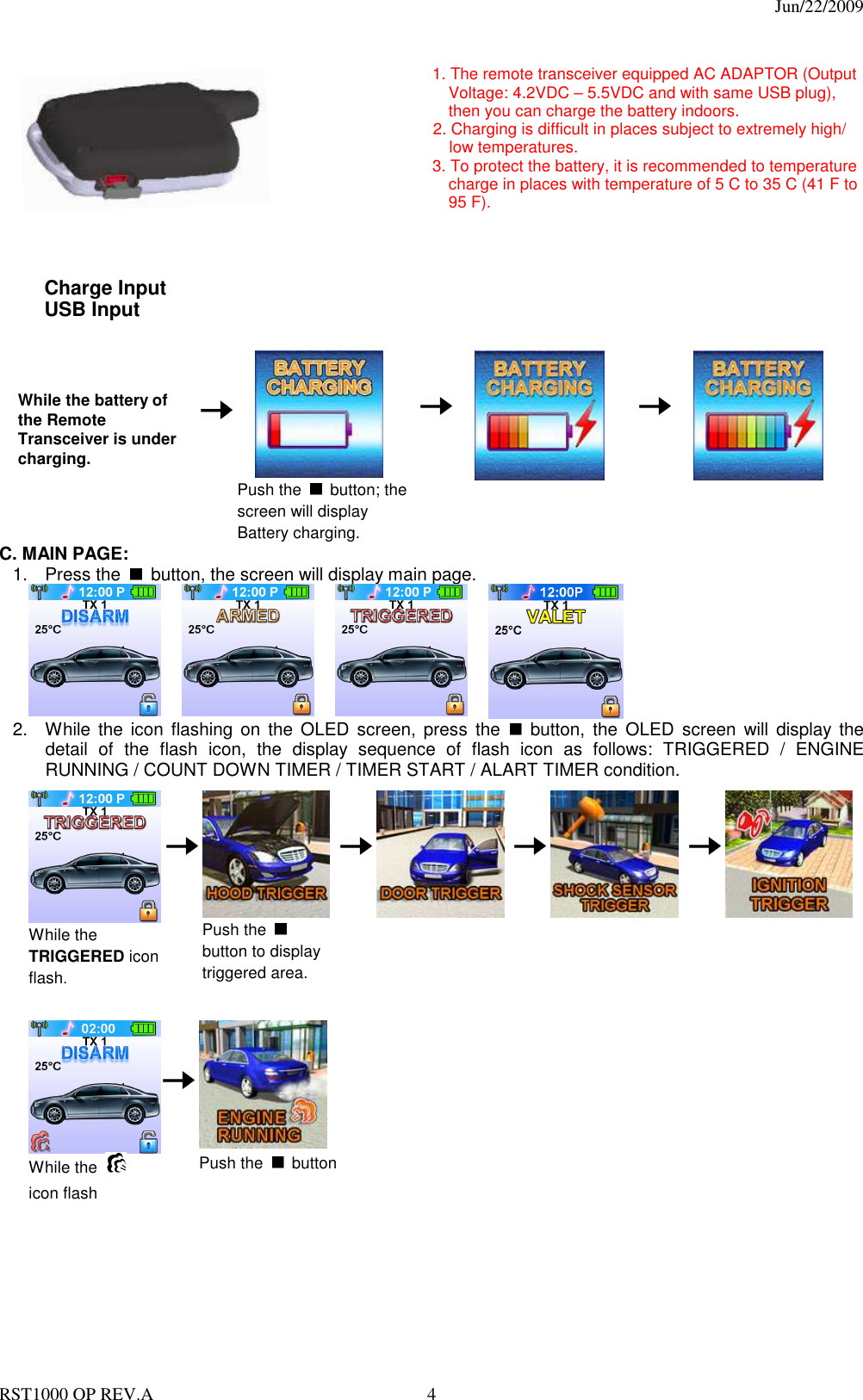
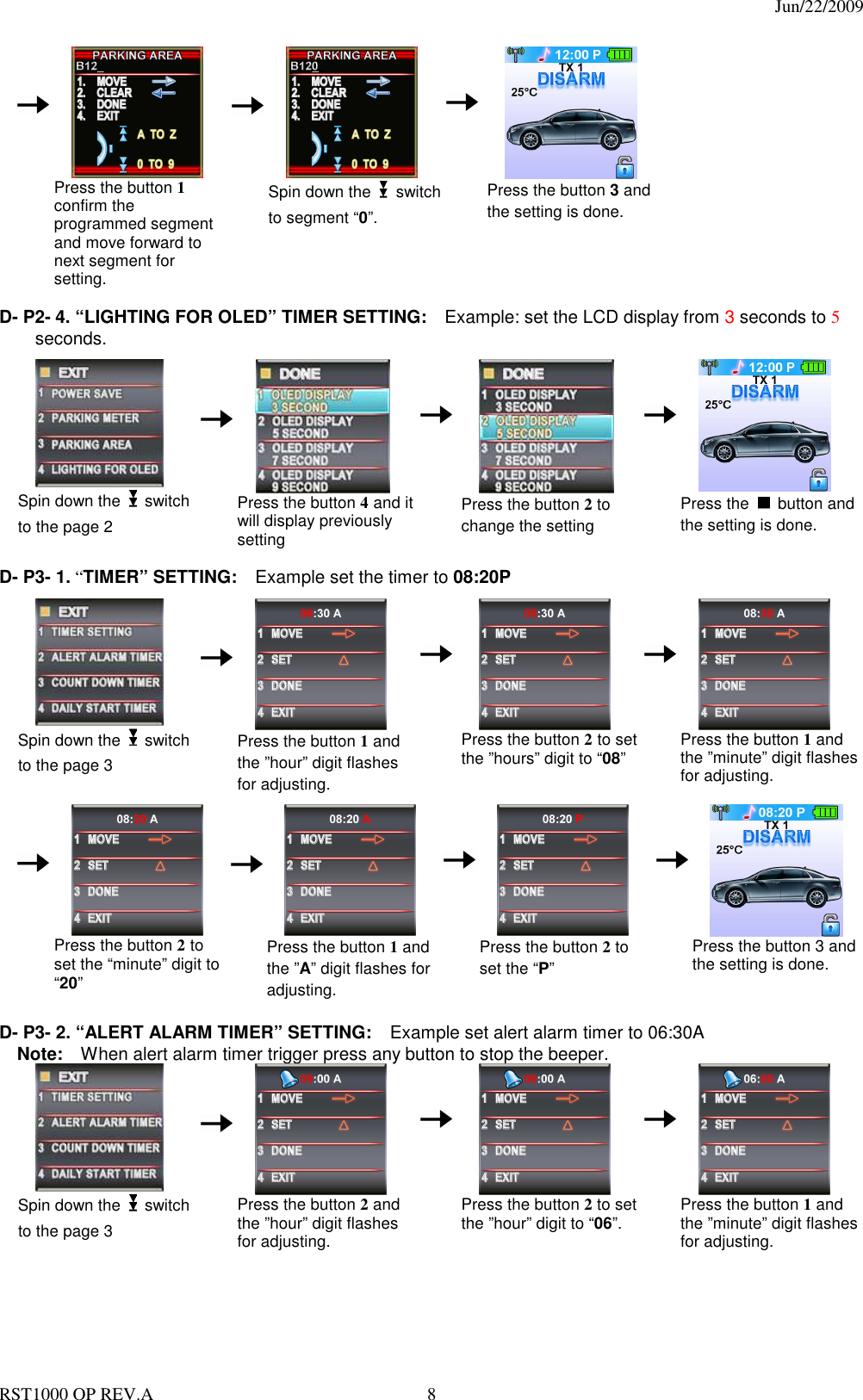
![Jun/22/2009 RST1000 OP REV.A 13 long as you wish. To exit passive by-pass, press the transmitter or button and the system will return to normal status. G. ACTIVE DISARMING – UNLOCK & DISARM: 1. Press button on the transmitter. 2. The siren will chirp twice and parking light flash twice to indicating that the security system is now disarmed. The vehicle’s door will unlock and dome light turns on for 30 seconds upon disarming when interfaced with the security system. SILENT DISARMING: Spin up the switch to the page 1 and then press the “Silent Disarm” button or press the transmitter and buttons at the same time to disarm your security system, No chirp sound will be heard, arm and disarm confirmation will be through the vehicles parking lights only. TAMPER DISARMING: If alarm triggered, upon disarming the system, the siren will chirp 4 times and the parking light will flash 3 times. PATHWAY ILLUMINATION: This feature turns the parking lights “ON” for 30 seconds upon an unlock signal and for 10 seconds upon the lock signal. (Programming required) TWO STEPS DOOR UNLOCK: This feature will independently unlock the driver’s door only when disarming the security system. Pushing the button a second time within 3 seconds will unlock the other doors. (Additional installation is required) AUTOMATIC RE-ARM: If this feature is selected, the security system will automatically re-arm itself in 60 seconds after disarming with remote transmitter. Automatic rearm will cancel if the ignition is turned ON and will pause if any door is opened before the 60 seconds timer has elapsed. H. DISARMING WITHOUT A TRANSMITTER OVERRIDES THE ALARM WITHOUT PASSWORD PIN CODE: (Factory Default Setting) The Override function may be used if the remote transmitter is lost or inoperative. 1. Enter the vehicle and turn the ignition switch to 'ON’ position. (Alarm will sound.) 2. Within 10 seconds push and release the valet switch The alarm will stop sounding and enter the disarmed mode. You can now start and operate the vehicle normally. OVERRIDE THE ALARM WITH PASSWORD PIN CODE: If the valet switch is located in a place that can be easily found, this security system allows the consumer to program a password pin code offering a higher level of security. 1. Enter the vehicle and turn the ignition switch to the 'ON’ position. (Alarm will sound.) 2. Within 5 seconds, enter your chosen the first digit code by pressing and releasing the Valet Switch. (When you are finished with the above procedures, the system's siren stops alarming and the parking lights stop flashing, but the vehicle cannot be started and driven away.) 3. If you use one digit to be a password pin code, skip to Step 6. If you use two digits to be a password pin code, advance to Step 4. 4. Within 15 seconds of the last digit code enter (the 1st code), turn the Ignition Switch “Off” and then “On”. 5. Within 15 seconds, enter your chosen of the second digit code by press and release the Valet Switch. 6. Turn the ignition switch to the “OFF” position. [4] Chirps form siren/horn, [3] flash from parking light to indicate the system was disarmed. Note: If someone keys-in the wrong password pin code, the system allows him to make 2 mistakes. If the third code is still wrong, it will automatically shut down for 5 minutes. During this period the system will not accept any code and the LED will “pause on” (the LED will turn on 1 second and turn off 0.1 second). EXAMPLE: To Override The System With The Password Code 83, you would; 1. Enter the vehicle and turn the ignition switch to 'ON’ position. (Alarm will sound.) 2. Within 5 seconds, Press and Release the Valet Switch 8 times (When finish the above procedure, the system's siren will stop alarming and the parking lights will stop flashing, but the vehicle cannot be started and driven away.) 3. Within 15 seconds of the last digit code enter (the 1st code), turn the Ignition Switch “Off” and then “ON”. 4. Within 15 seconds, Press and Release the Valet Switch 3 times](https://usermanual.wiki/Advance-Security/TR32/User-Guide-1143850-Page-13.png)
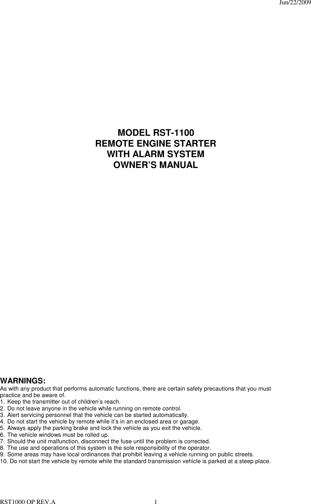
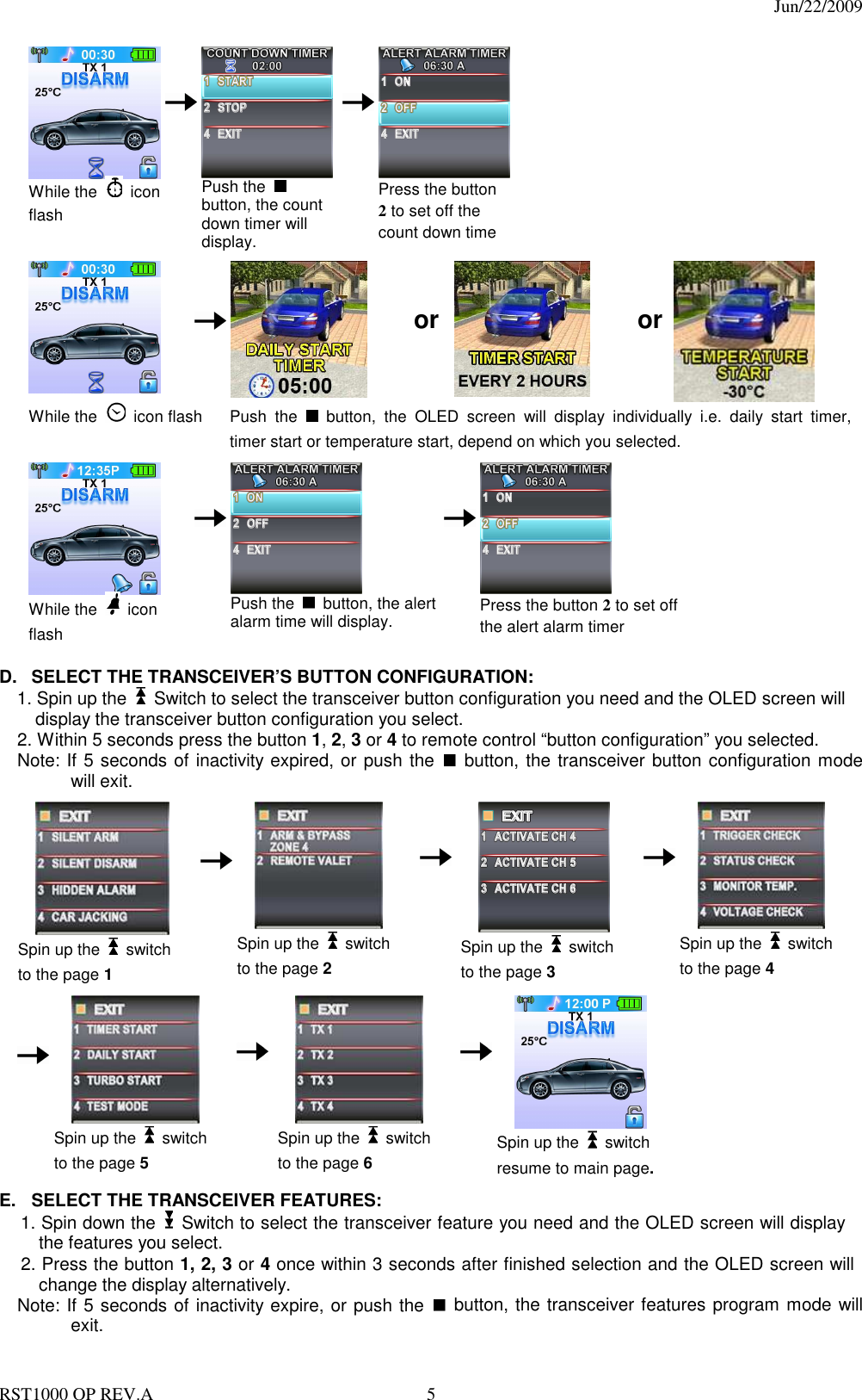
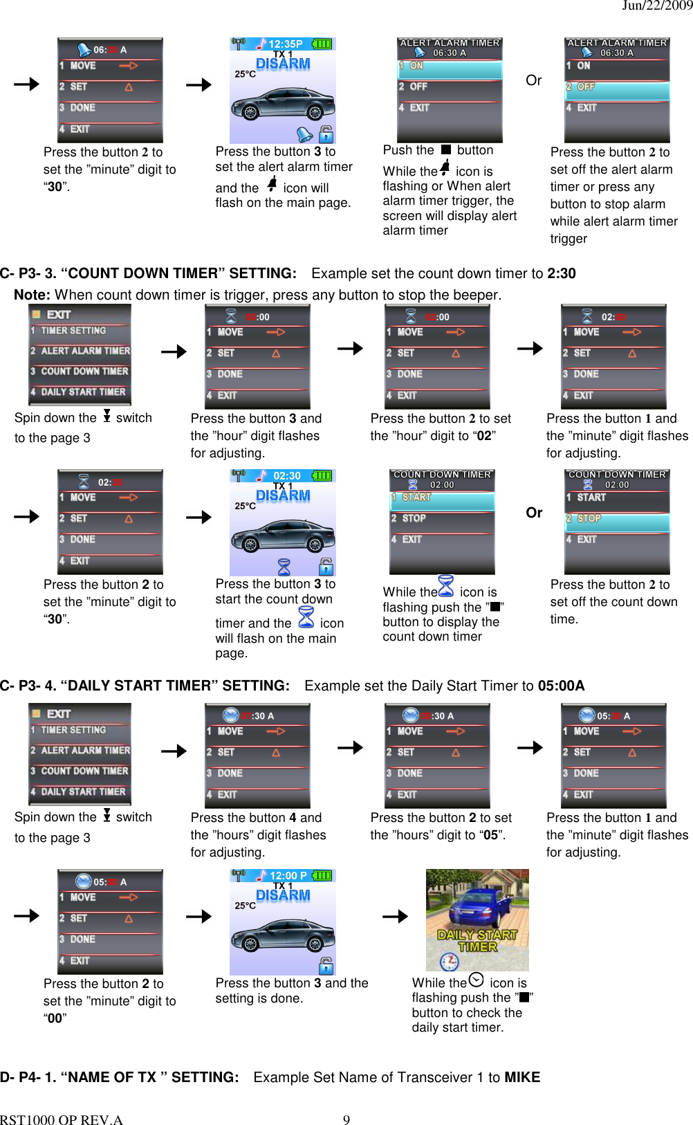
![Jun/22/2009 RST1000 OP REV.A 14 5. Turn the Ignition Switch to “Off” position. [4] Chirps form siren/horn and [3] flashes from the parking light will indicate the system has been disarmed. I. VALET MODE: (System in Disarm or Valet mode) The valet switch allows you to temporarily bypass all alarm function, eliminating the need to hand your transmitter to a parking attendants or a garage mechanic. When the system is in valet mode, all alarm function and remote start functions are bypassed, however the remote panic feature and remote door locks will remain operational. To use the valet mode, the system must first be disarmed. Enter Valet Mode: 1. From the disarmed condition, turn the ignition to the “ON” position. 2. Push and hold valet switch for 2 seconds until the LED turns on solid. The LED will remain on as long as the system is in 'valet mode'. Exit Valet Mode: 1. To return to normal operation, turn the ignition 'ON'. 2. Push and hold valet switch for 2 seconds. The LED will turn off to indicate the system has exiting the valet mode. J. CAR LOCATOR While the system is armed, press the button to activate car locator function. The siren will chirp 6 times. The parking lights will flash 12 times, for you to easily locate your vehicle. K. PANIC FUNCTION: The transmitter can be used as a remote panic switch to manually trigger the alarm in case emergency. 1. Press and hold the button for 3 second. The alarm will immediately sound and the “Panic” icon will display on the OLED screen. 2. During panic mode, the normal function of this transmitter button will be suspended. The transmitter and buttons can be used to lock and unlock the door (if the option is installed), however once the button is pressed, the vehicle’s starter disable device, (where installed) will be enable allowing the vehicle to start. 3. To stop the alarm press the transmitters . The panic mode will be turned off immediately. 4. If the button is not pressed, the alarm will automatically stop after 30 seconds. L. TRIGGERING THE SYSTEM When armed, your vehicle is protected as follows: 1.Light impact will trigger the warn-away signal. 2.Heavy impacts / Doors open / Hood open / Trunk open / Turning on the ignition key will trigger the programmed sequence. The starter disable relay (if installed) prevents the vehicle’s starter from cranking. The siren, horn, parking lights, and dome light will turn on to alert of an intrusion for 30 seconds. Then it will stop and automatically reset and re-arm. If the sensors or detectors are still active, the alarm system will sound a maximum of 6 times of 30 seconds cycles. Stop The Melody Sound: While triggering the alarm the OLED screen will alert user through melody sound and flashing trigger icon, press any button on the OLED remote transceiver to stop melody sound.](https://usermanual.wiki/Advance-Security/TR32/User-Guide-1143850-Page-14.png)