Advance Security TR32 Remote Control User Manual 090702 C3 RS1100
Advance Security Inc Remote Control 090702 C3 RS1100
Users Manual
Jun/22/2009
RST1000 OP REV.A 1
MODEL RST-1100
REMOTE ENGINE STARTER
WITH ALARM SYSTEM
OWNER’S MANUAL
WARNINGS:
As with any product that performs automatic functions, there are certain safety precautions that you must
practice and be aware of.
1. Keep the transmitter out of children’s reach.
2. Do not leave anyone in the vehicle while running on remote control.
3. Alert servicing personnel that the vehicle can be started automatically.
4. Do not start the vehicle by remote while it’s in an enclosed area or garage.
5. Always apply the parking brake and lock the vehicle as you exit the vehicle.
6. The vehicle windows must be rolled up.
7. Should the unit malfunction, disconnect the fuse until the problem is corrected.
8. The use and operations of this system is the sole responsibility of the operator.
9. Some areas may have local ordinances that prohibit leaving a vehicle running on public streets.
10. Do not start the vehicle by remote while the standard transmission vehicle is parked at a steep place.

Jun/22/2009
RST1000 OP REV.A 2
OLED REMOTE TRANSCEIVER:
A. OLED DISPLAY……………………………….………………………………………………………………………… 4
B.
CHARGE THE BATTERY
……….…………………………………………………………………………..…….. 4
C.
MAIN PAGE
…………………………………………………………………………………………………………… 5
D.
SELECT THE TRANSCEIVER’S BUTTON CONFIGURATION
…………………………………………. 6
E.
SELECT THE TRANSCEIVER FEATURES
…………………………………………..………………………. 6
P1-1: Enable / Disable Bi Sound While Pressing Button (7)
P1-2: Button Lock Setting (7)
P1-3: Melody / Vibration Mode (7)
P1-4: Demo Mode (8)
P2-1: Power Save Mode (8)
P2-2: Parking Meter Setting (8)
P2-3: Parking Area Setting (8)
P2-4: “Light For OLED” Timer Setting (9)
P3-1: Timer Setting (9)
P3-2: Alert Alarm Timer Setting (9)
P3-3: Count Down Timer Setting (10)
P3-4: Daily Start Timer Setting (10)
P4-1: Name of
Transceiver
Setting (11)
P5-1: Name of
Channel
Setting (11)
P6-1: Language Setting (11)
P6-4: Set To Defaults (12)
TABLE OF CONTENTS:
A. REMOTE TRANSMITTER OPERATION ……………………………………….………………….………….…… 12
B. LED DISPLAY .……………..……………………………………………………………………….……………..……12
C. CHIRP INDICATOR ..………..……………………………………………………………………………….…..……. 13
D. PARKING LIGHT …….……..…………………………………………………………………………..……….….…. 13
E. ACTIVE ARMING – ARM & LOCK .……………………………………………………………………….…………. 13
Ajar Warning / Silent Arming / Sensor By-Pass / Noiseless Mode / Hidden Alarm Mode / Auto Immobiliser /
Arming While Driving
F. PASSIVE ARMING .…………………………………………..…………………….………………………….….…… 14
Passive Arming with Passive Door Locking / Passive Arming By-Pass
G. ACTIVE DISARMING – UNLOCK & DISARM .…………………………………………………..…………………. 14
Silent Disarming / Tamper Disarming / Pathway Illumination / Two Steps Door Unlock / Automatic Re-Arm
H. DISARMING WITHOUT A TRANSMITTER .……………..…………………………………………………..…….... 14
Overrides the Alarm without Password Pin Code / Overrides the Alarm With Password Pin Code
I. VALET MODE .……………..…………………………………………………………………….…………………..…... 15
J. CAR LOCATOR .……………………………………………………………………….……………………………...… 15
K. PANIC FUNCTION .……………………………………………………………………………..….……………….….. 15
L. TRIGGER THE SYSTEM .………………………………………..………………………..………….………….…….. 15
Stop The Melody Sound / Noise Abatement Circuit
M. ANTI CAR- JACKING .…………………………………………………………………………………………….…….. 16
N. SYSTEM’S TRIGGER CHECK ……………………………………………………………….….….…………....……. 17
O. SYSTEM’S STATUS CHECK ……………………………………………………………..……….……………..……. 17
P. DRIVER PAGING / LOSE AND FOUND ………………………….…………..……………………...………………...17
Q. DOME LIGHT CONVENIENCE DELAY & SUPERVISION ……………………..………………….………..……....17
R. IGNITION CONTROL THE DOOR LOCK/UNLOCK. ………..………………….……………………………..…..….17
S. TRUNK RELEASE (CHANNEL 3) OUTPUT ………..……………………………………………….……………..….17
T. CHANNEL 4 / 5 / 6 / 7 TIMER CONTROL OUTPUT ………..……………………………………………….………..17
U. MULTI-VEHICLE SECURITY OPREATION: ………..……………………………………………………………….…18
V. OUT OF RANGE INDICATION: ………..…………………………….….…………………………………………….…18
W. POWER SAVER MODE: …….…..……………………………………………………………….…….……………….. 18
X. POWER ON MEMONRY: ………..……………………………………………………………….…….……………….. 18
REMOTE START OPERATION:
A. TO REMOTE START THE VEHICLE ………..……………………………………………………………..………….. 19
B. ENGINE START MEMORIZING FOR THE VEHICLE WITH STANDARD TRANSMISSION GEAR …………... 19
C. TO OPERATE THE VEHICLE WHILE RUNNING ON THE REMOTE START ………………………………..….. 19
D. TEMPORARY STOP FEATURE ……………………………………………….………………….…………………… 20
E. TURBO TIMER MODE ……………………..………………………………….……………….………...………..….… 20
F. TIMER START …………………………………………….…………….……………………….…..…………………… 20
3 (2 or 1) Hours Timer Start / Daily Timer Start / Cancel the Timer Start
G. TEMPERATURE CHECK …………….……………………………………………….…...……….…………….….… 20
H. TO TURN OFF THE REMOTE START ……………………………………………….….…….………………….….…20
I. SHUT-DOWN INPUT FOR REMOTE STARTER …………………………….……………………………..….………. 21
J. DISABLING THE REMOTE START SYSTEM …………………………….……………………..……………….….… 21
TEST MODE …………………..…………….……………………………………………….…...……….………..…….…… 21
SHUTDOWN DIAGNOSTICS …………….……………………………………………….…...……….………..…….…… 21
Jun/22/2009
RST1000 OP REV.A 3
Vibration Mode
REMOTE TRANSCEIVER (TX)
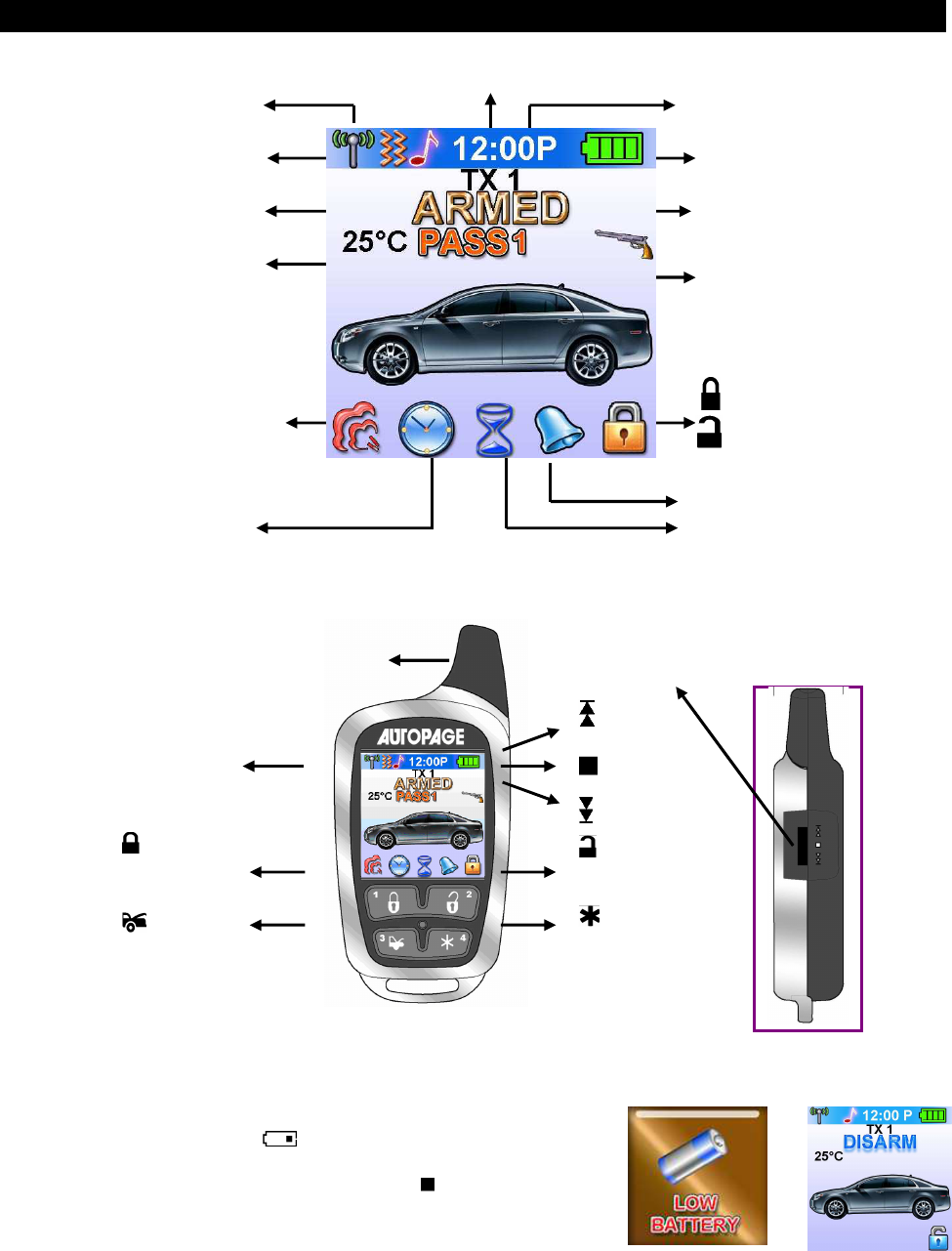
A. OLED DISPLAY
I n case the remote transceiver malfunction,
errors or freeze of display, it is recommended
to reset your remote transceiver.
B. CHARGE THE BATTERY
Power by built-in 3.7V lithium polymer b
attery, if the OLED screen
display low battery or
is flash, charge your remote
transceiver. While the battery of the Remote Transceiver is under
the battery charging, you can push the ” ”
button to check
charging condition.
switch
Button
Button
1
OLED Display
Name of Transmitter
Button
Button
3
Button
Button
2
Button
Button
4
switch
button
Antenna
Level and
push switch
Battery Level
Car Jacking
In – Range Indicator
Door Lock
Door Unlock
Alarm Status
Temperature
Engine Running
Melody Mode
Timer Start Alert Alarm
Count Down Timer
Parking Timer
Timer
Bypass Sensor 1
(Zone 4)
Bypass Sensor 2
(Zone 6)
Jun/22/2009
RST1000 OP REV.A 4
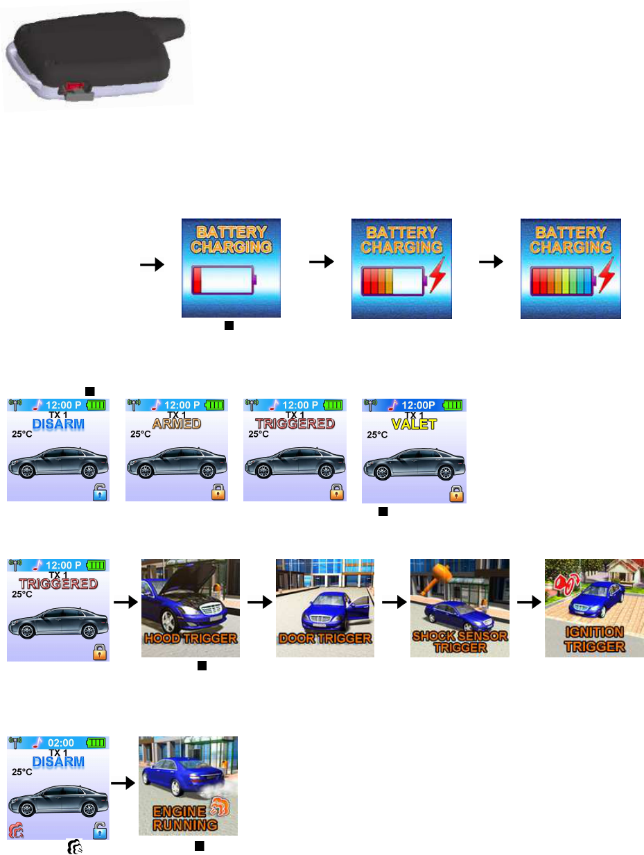
1. The remote transceiver equipped AC ADAPTOR (Output
Voltage: 4.2VDC – 5.5VDC and with same USB plug),
then you can charge the battery indoors.
2. Charging is difficult in places subject to extremely high/
low temperatures.
3. To protect the battery, it is recommended to temperature
charge in places with temperature of 5 C to 35 C (41 F to
95 F).
While the battery of
the Remote
Transceiver is under
charging.
Push the button; the
screen will display
Battery charging.
C. MAIN PAGE:
1. Press the button, the screen will display main page.
2. While the icon flashing on the OLED screen, press the button, the OLED screen will display the
detail of the flash icon, the display sequence of flash icon as follows: TRIGGERED / ENGINE
RUNNING / COUNT DOWN TIMER / TIMER START / ALART TIMER condition.
While the
TRIGGERED icon
flash.
Push the
button to display
triggered area.
While the
icon flash
Push the button
Charge Input
USB Input
Jun/22/2009
RST1000 OP REV.A 5
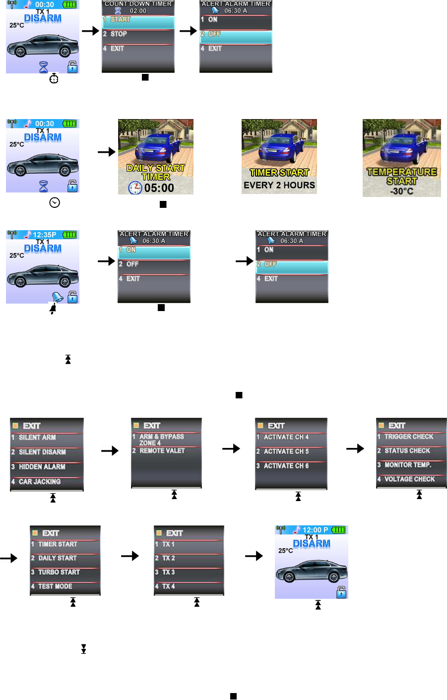
While the
icon
flash
Push the
button, the count
down timer will
display.
Press the button
2 to set off the
count down time
or
or
While the icon flash
Push the button, the OLED screen will display individually i.e. daily start timer
,
timer start or temperature start, depend on which you selected.
While the icon
flash
Push the button, the alert
alarm time will display.
Press the button 2 to set off
the alert alarm timer
D. SELECT THE TRANSCEIVER’S BUTTON CONFIGURATION:
1. Spin up the Switch to select the transceiver button configuration you need and the OLED screen will
display the transceiver button configuration you select.
2. Within 5 seconds press the button 1, 2, 3 or 4 to remote control “button configuration” you selected.
Note: If 5 seconds of inactivity expired, or push the button, the transceiver button configuration mode
will exit.
Spin up the switch
to the page 1
Spin up the switch
to the page 2
Spin up the switch
to the page 3
Spin up the switch
to the page 4
Spin up the switch
to the page 5
Spin up the switch
to the page 6
Spin up the switch
resume to main page.
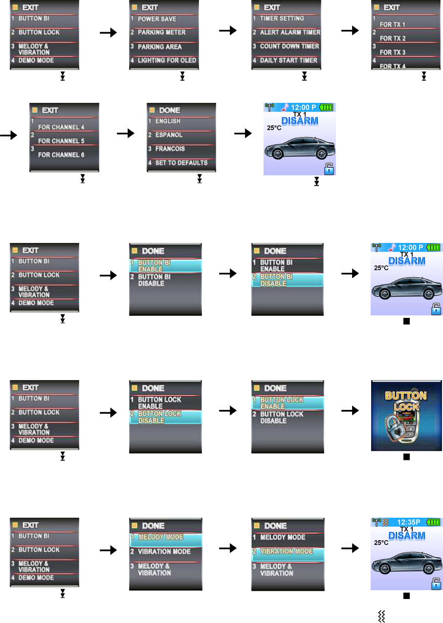
E. SELECT THE TRANSCEIVER FEATURES:
1. Spin down the Switch to select the transceiver feature you need and the OLED screen will display
the features you select.
2. Press the button 1, 2, 3 or 4 once within 3 seconds after finished selection and the OLED screen will
change the display alternatively.
Note: If 5 seconds of inactivity expire, or push the button, the transceiver features program mode will
exit.
Jun/22/2009
RST1000 OP REV.A 6
Spin down the
switch
to the page 1
Spin down the
switch
to the page 2
Spin down the
switch
to the page 3
Spin down the
switch
to the page 4
Spin down the
switch
to the page 5
Spin down the
switch
to the page 6
Spin down the
switch
resume to main page.
E- P1- 1. “BUTTON BI” SETTING: Example: Set the “Button Bi Disable”.
It has a short “bi” sound while pressing the button of the remote transceiver
Spin down the
switch
to the page 1
Press the button 1 and it
will display previously
setting
Press the button 2 to
change the setting
Press the button and
the setting is done.
E- P1- 2. “BUTTON LOCK” SETTING: Example: Set the “Button Lock Enable”.
Spin down the
switch
to the page 1
Press the button 2 and it
will display previously
setting
Press the button 1 to
change the setting
Press the button and
the setting is done.
D- P1- 3. “MELODY / VIBRATION MODE” SETTING: Example: set the Vibration mode.
Spin down the
switch
to the page 1
Press the button 3
and it
will display previously
setting
Press the button 2 to
change the setting
Press the button and
the setting is done also
the
icon
will display
on the OLED screen
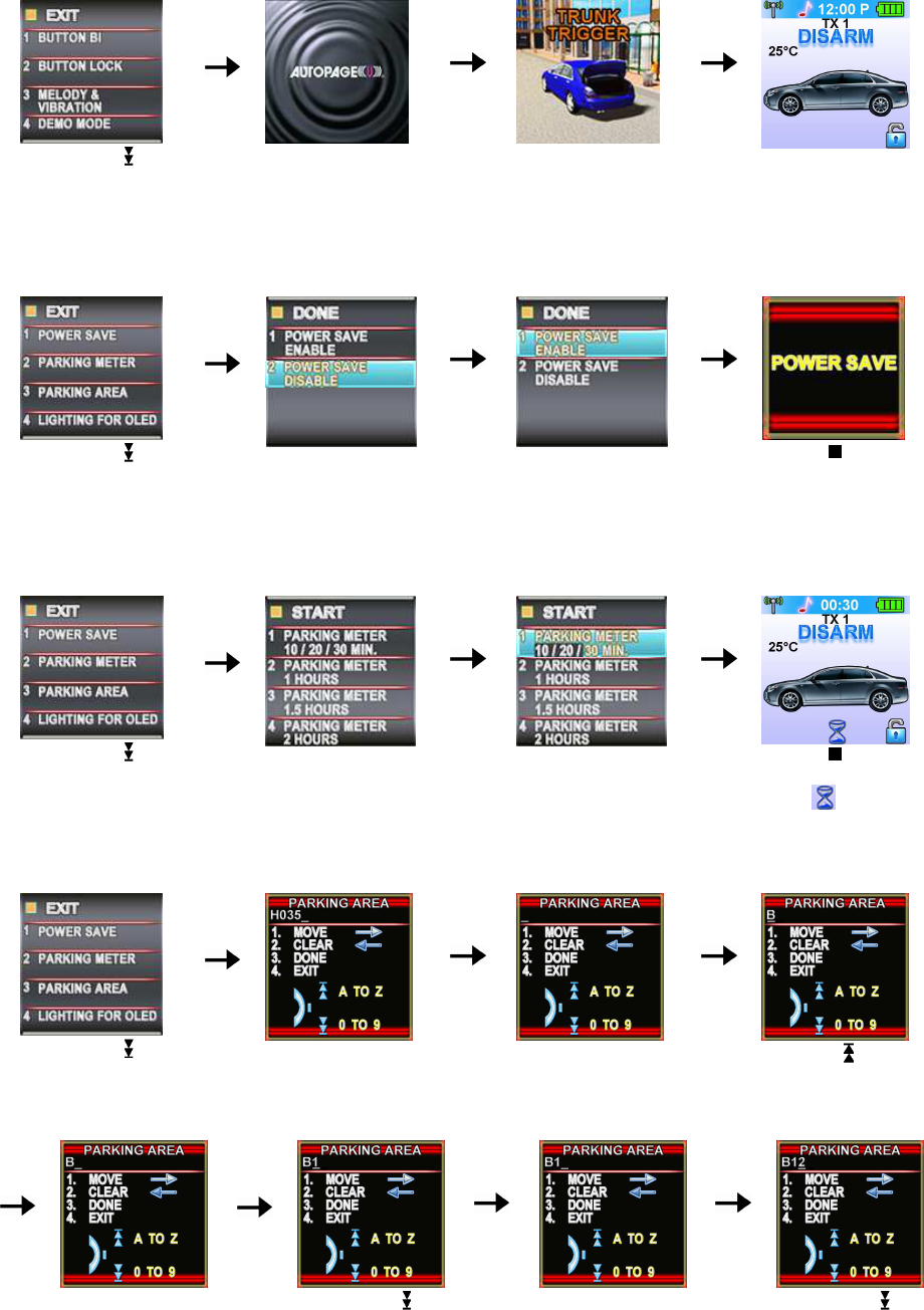
E- P1- 4. “DEMO MODE”:
Jun/22/2009
RST1000 OP REV.A 7
Spin down the
switch
to the page 1
Press the button 4 to
start Demo movie
Demo movie playing
Press the any Button to
exit.
E- P2- 1. “POWER SAVE” SETTING: Example set the “Power Save Enable”.
While the power save mode, the LCD remote transceiver uses “0” current to save the battery power.
Spin down the
switch
to the page 2
Press the button 1 and it
will display previously
setting.
Press the button 1 to
change the setting.
Press the button and
the setting is done.
E- P2- 2. “PARKING METER” SETTING: Example set the “Parking Meter 30 min..
Note: When “parking meter” trigger presses any button to stop the beeper.
Spin down the switch
to the page 2
Press the button 2
Press the button 1 three
times to set the parking
timer to 30 minutes.
Press the button to
start the parking meter
and the icon will
flash on the main page.
D- P2- 3. “PARKING AREA” SETTING: Example set the “Parking Area.” to “B120
Spin down the switch
to the page 2
Press the button 3, it will
display previously
parking area
Press the button 2 to
clear the parking area,
and the “
-
” flashes for
setting.
Spin up the
switch to
set segment “B”
Press button 1 confirm
the programmed
segment and move
forward to next
segment for setting.
Spin down the
switch to set segment
“1”
Press button 1 confirm
the programmed
segment and move
forward to next
segment for setting.
Spin down the
switch to set segment
“2”.
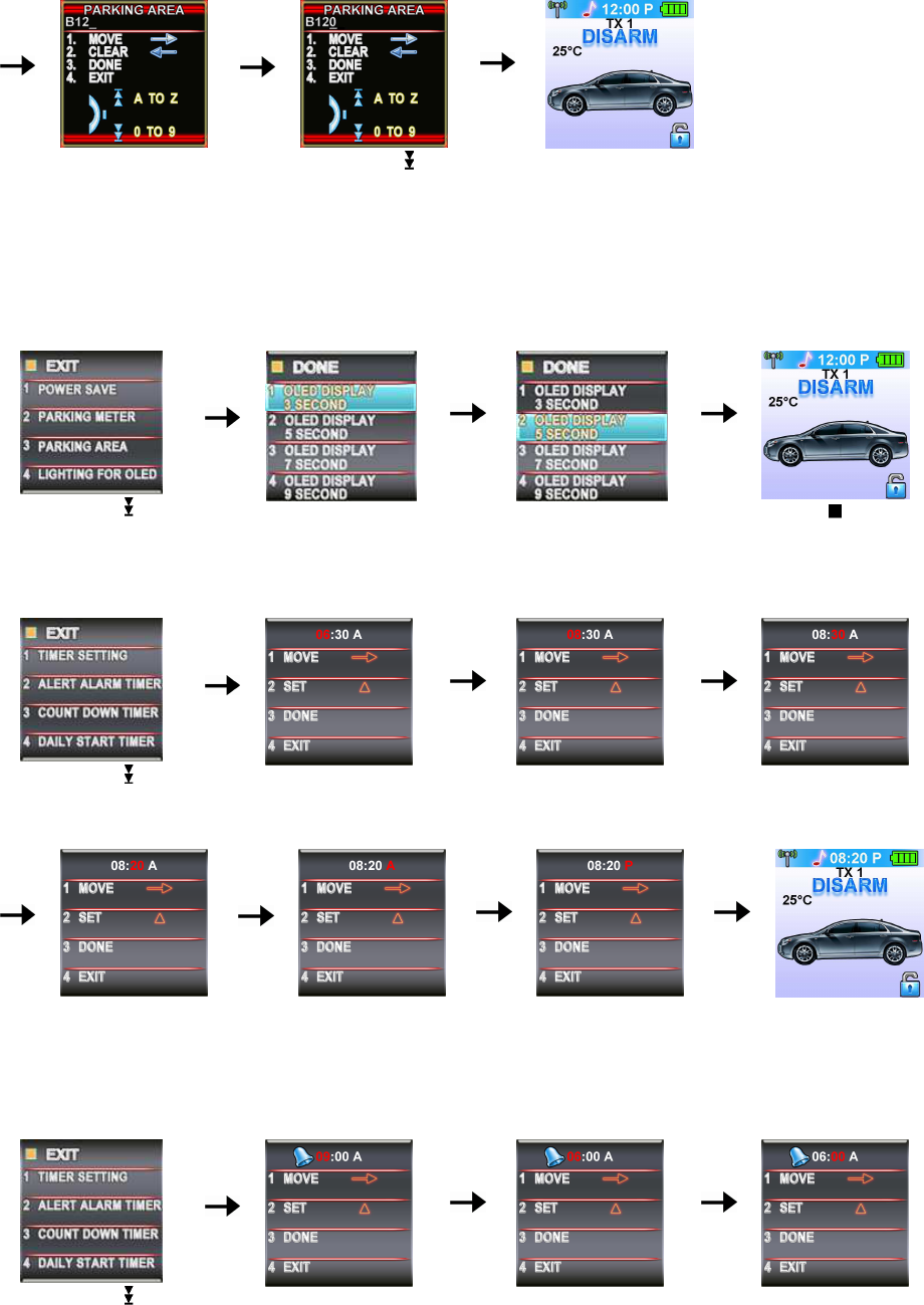
Jun/22/2009
RST1000 OP REV.A 8
Press the button 1
confirm the
programmed segment
and move forward to
next segment for
setting.
Spin down the
switch
to segment “0”.
Press the button 3 and
the setting is done.
D- P2- 4. “LIGHTING FOR OLED” TIMER SETTING: Example: set the LCD display from 3 seconds to 5
seconds.
Spin down the switch
to the page 2
Press the button 4
and it
will display previously
setting
Press the button 2 to
change the setting
Press the button and
the setting is done.
D- P3- 1. “TIMER” SETTING: Example set the timer to 08:20P
Spin down the switch
to the page 3
Press the button 1 and
the ”hour” digit flashes
for adjusting.
Press the button 2
to set
the ”hours” digit to “08”
Press the button 1 and
the ”minute
” digit flashes
for adjusting.
Press the button 2
to
set the “minute” digit to
“20”
Press the button 1 and
the ”A” digit flashes for
adjusting.
Press the button 2 to
set the “P”
Press the button 3 and
the setting is done.
D- P3- 2. “ALERT ALARM TIMER” SETTING: Example set alert alarm timer to 06:30A
Note: When alert alarm timer trigger press any button to stop the beeper.
Spin down the switch
to the page 3
Press the button 2 and
the ”hour” digit flashes
for adjusting.
Press the button 2 to set
the ”hour” digit to “06”.
Press the button 1 and
the ”minute
” digit flashes
for adjusting.
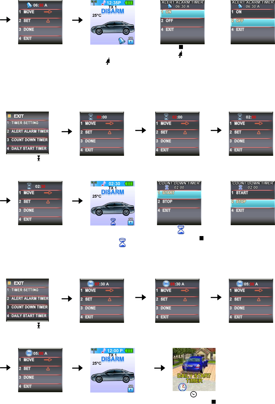
Jun/22/2009
RST1000 OP REV.A 9
Press the button 2 to
set the ”minute” digit to
“30”.
Press the button 3 to
set the alert alarm timer
and the icon will
flash on the main page.
Push the button
While the icon is
flashing or When alert
alarm timer
trigger, the
screen will display alert
alarm timer
Or
Press the button 2 to
set off the alert alarm
timer or press any
button to stop alarm
while alert alarm timer
trigger
C- P3- 3. “COUNT DOWN TIMER” SETTING: Example set the count down timer to 2:30
Note: When count down timer is trigger, press any button to stop the beeper.
Spin down the switch
to the page 3
Press the button 3 and
the ”hour” digit flashes
for adjusting.
Press the button 2 to set
the ”hour” digit to “02”
Press the button 1 and
the ”minute
” digit flashes
for adjusting.
Press the button 2 to
set the ”minute” digit to
“30”.
Press the button 3 to
start the count down
timer and the icon
will flash on the main
page.
While the icon is
flashing push the ” ”
button to display the
count down timer
O
r
Press the button 2 to
set off the count down
time.
C- P3- 4. “DAILY START TIMER” SETTING: Example set the Daily Start Timer to 05:00A
Spin down the switch
to the page 3
Press the button 4
and
the ”hours” digit flashes
for adjusting.
Press the button 2
to set
the ”hours” digit to “05”.
Press the button 1 and
the ”minute
” digit flashes
for adjusting.
Press the button 2 to
set the ”minute” digit to
“00”
Press the button 3 and the
setting is done.
While the icon is
flashing push the ” ”
button to check the
daily start timer.
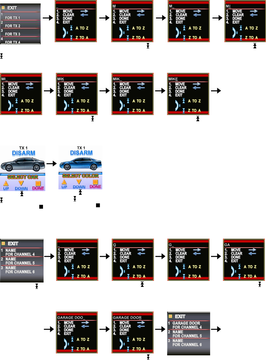
D- P4- 1. “NAME OF TX ” SETTING: Example Set Name of Transceiver 1 to MIKE
Jun/22/2009
RST1000 OP REV.A 10
Spin down the
switch to the
page 4
Press the button1
and the “
-
” flash
for setting the 1
st
letter.
Spin down the
switch to set the
“M”.
Press the button 1
and the “
-
” flash
for setting next
letter.
Spin up the ”
switch to set
the ”I”.
Press the button 1
and the “
-
” flash
for setting.
Spin down the
switch to set
the ”K”.
Press the button
1 and the “
-
” flash
for setting.
Spin up the
switch to set
the ”E”.
Press button 3
done confirm
your program
Spin up or down
to select car
photo, Push the
button to confirm
your selection
Spin up or
down to select
color, Push the
button to confirm
your selection
D- P5- 1. “NAME OF CHANNEL ” SETTING: Example Set Name of channel 4 to GARAGE DOOR
Spin down the
switch to the page
5
Press the button
1 and the “
-
”
flashes for
setting.
Spin up the
switch to set
the ”G”.
Press the button
1 and the “
-
”
flashes for
setting.
Spin down the
switch to setting
the ”A”.
Following the
above step to
setting
GARAGE
DOOR
Press the button
1 and the “
-
”
flashes for
setting.
Spin down the
switch to set
the ”R”
Press button 3
and the setting is
done.
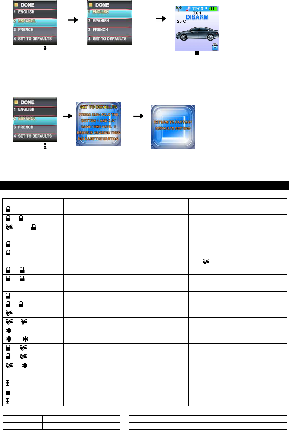
D- P6- 1. LANGUAGE SETTING: Example set the Language to
English
Jun/22/2009
RST1000 OP REV.A 11
Spin down the switch
to the page 6
Press the button
1
to set the
Language to ”ENGLISH”.
Press the button and the
setting is done.
D- P6- 4. SET TO DEFAULTS:
Spin down the
switch to the page 6
Press the button
4
.
Press the button
1
&
2
at same time to set
the remote defaults.
OPERATION:
A. REMOTE TRANSMITTER OPERATION:
Transmitter Button System Function Remark
1
Lock Doors & Arm System / Button 1
- Arm and Bypass Zone 4. Shock Sensor Press twice within 3 seconds
then Arm System and Hidden, (Silent) Alarm
Function
Press within 3 seconds
Car Locator Upon armed
(3-second)
Panic function Press and Hold for 3 seconds.
To cancel.
+ Silent Arming / Disarming Ignition in "off" position.
+ (2-second) Active Anti Car-Jacking Mode. Programming
required
Ignition in "on" position press and
hold for 2 seconds
2
Unlock Doors & Disarm System / Button 2
-
--
- Two Steps Door Unlock & Disarm System Press twice within 3 seconds.
3
(3-second) Trunk Release (Channel 3) Press and Hold for 3 seconds
- Passive Arming By-pass While the system Disarmed.
4
Turn ON & Off The Remote Start / Button 4 .
-
--
- Safety Start. Programming required Press twice within 3 seconds.
+ Channel # 4 Timer Output Programming required
+ Channel # 5 Timer Output Programming required
+ Channel # 6 Timer Output Programming required
II
IIII
II
Switching code For 2nd
Car Operation. For regular remote transmitter
Button Function Selection For Two way Remote transceiver
Confirm Button / Back to Main Page For Two way Remote transceiver
Feature Selection For Two way Remote transceiver
B. LED display:
LED Function
LED Function
Off Disarmed 1 flashes... pause Zone 1 / Trigger on Hood
Jun/22/2009
RST1000 OP REV.A 12
Slow Flash Armed 2 flashes... pause Zone 2 / Trigger on Trunk
Fast Flash Passive Arming 3 flashes... pause Zone 3 / Trigger on Door Switch
On (Solid) Valet Mode 4 flashes... pause Zone 4 / Trigger on Shock Sensor
Pause On Password Lock-Out
5 flashes... pause Zone 5 / Trigger on Ignition Switch
C. CHIRP INDICATORS: D. PARKING LIGHT:
Chirp Function
Parking light Function
1 chirp Arm 1 flash Arm
2 chirps Disarm 2 flashes Disarm
3 chirps Ajar Warning 3 flashes Disarm / Triggered
4 chirps Disarm / Triggered 12 flashes Car Locator
6 chirps Car Locator Constant On Under Remote Start
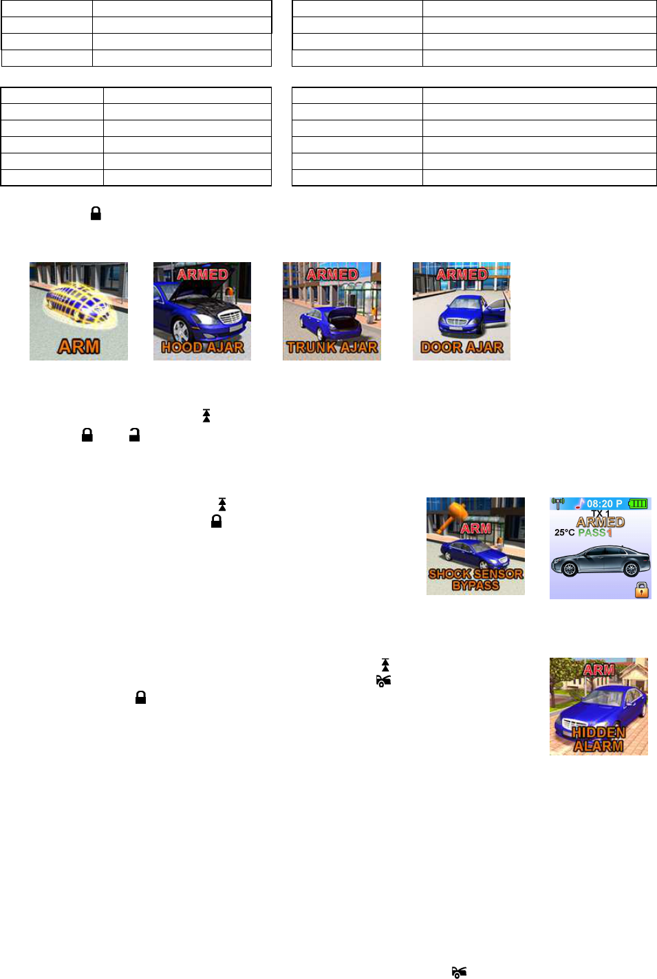
E. ACTIVE ARMING – LOCK & ARM:
1. Press the button on the transmitter.
2. The siren will chirp once and parking light will flash once indicating that the system is now armed. The
vehicle door will lock upon arming when interfaced with the security system.
AJAR WARNING: If the siren sounds 3 chirps, then you have left a door, trunk, or hood lid ajar.
SILENT ARMING:
Spin up the
switch to the page
1
and then press the “Silent Arm” button
or press the
transmitter and buttons at the same time to arm your security system, No chirp sound will be heard,
arm confirmation will be through the vehicles parking lights only.
SENSOR BY-PASS:
Bypass The Zone 4: Spin up the
switch to the page
2
and then
press the button
1
or press the button on
the transmitter two
times within 3 seconds. This will arm t
he security system and
by-pass the zone 4-shock sensor.
The system will chirp one additional time to confirm the sensor bypass mode was activated. The sensor
bypass feature is programmed to activate for one arming cycle only. The security system will return to
normal operation during the next arming cycle.
HIDDEN ALARM FUNCTION (Silent Alarm): Spin up the switch to the page 1
and then press the “Hidden Alarm” button or press the button first; within 3
seconds press the button to activate the hidden alarm function. The security
system will arm and with “Hidden Alarm Function” The siren / horn will be silenced
even if the unit is triggered in the armed status. Notification will only be through the
hand held two-way remote.
F. PASSIVE ARMING (Programming Required)
Active arming / disarming is controlling your security system via the remote transmitter. This security
system is equipped with an optional Passive Arming feature which allows the security system to arm 30
seconds after the last door is closed. Operation is as follows.
1. Turn the ignition to the “OFF” position and exit the vehicle.
2. After all entrances are closed, the security system LED will flash fast for 30 seconds. If you reopen any
door / hood / trunk, the security system LED will stop flashing. It will begin flashing again once all of the
vehicle entrances are closed.
3. After 30-second timer has elapsed, the security system will automatically “ARM”. The siren will chirp [1]
time and the parking lights will flash [1] time.
PASSIVE ARMING WITH PASSIVE DOOR LOCKING:
The vehicle doors will automatically lock after passive arming cycle has been completed.
PASSIVE ARMING BY-PASS: While the system disarmed, Press the button twice, the security will
respond with [1] chirp and LED will turn “ON”. The security system will remain in this temporary state for as
Jun/22/2009
RST1000 OP REV.A 13
long as you wish. To exit passive by-pass, press the transmitter or button and the system will return to
normal status.
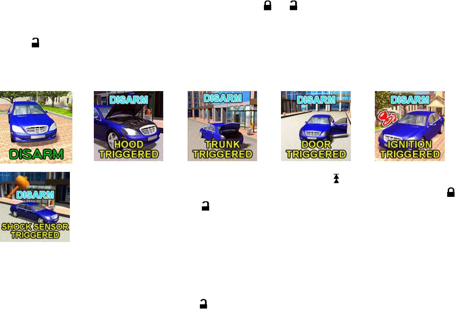
G. ACTIVE DISARMING – UNLOCK & DISARM:
1. Press button on the transmitter.
2. The siren will chirp twice and parking light flash twice to indicating that the security system is now
disarmed. The vehicle’s door will unlock and dome light turns on for 30 seconds upon disarming when
interfaced with the security system.
SILENT DISARMING:
Spin up the
switch to the page
1
and
then press the “Silent Disarm” button or press the transmitter
and buttons at the same time to disarm your security
system, No chirp sound will be heard, arm and disarm
confirmation will be through the vehicles parking lights only.
TAMPER DISARMING: If alarm triggered, upon disarming the system, the siren will chirp 4 times and the
parking light will flash 3 times.
PATHWAY ILLUMINATION: This feature turns the parking lights “ON” for 30 seconds upon an unlock
signal and for 10 seconds upon the lock signal. (Programming required)
TWO STEPS DOOR UNLOCK: This feature will independently unlock the driver’s door only when
disarming the security system. Pushing the button a second time within 3 seconds will unlock the
other doors. (Additional installation is required)
AUTOMATIC RE-ARM: If this feature is selected, the security system will automatically re-arm itself in 60
seconds after disarming with remote transmitter. Automatic rearm will cancel if the ignition is turned ON
and will pause if any door is opened before the 60 seconds timer has elapsed.
H. DISARMING WITHOUT A TRANSMITTER
OVERRIDES THE ALARM WITHOUT PASSWORD PIN CODE: (Factory Default Setting)
The Override function may be used if the remote transmitter is lost or inoperative.
1. Enter the vehicle and turn the ignition switch to 'ON’ position. (Alarm will sound.)
2. Within 10 seconds push and release the valet switch
The alarm will stop sounding and enter the disarmed mode. You can now start and operate the vehicle
normally.
OVERRIDE THE ALARM WITH PASSWORD PIN CODE:
If the valet switch is located in a place that can be easily found, this security system allows the consumer to
program a password pin code offering a higher level of security.
1. Enter the vehicle and turn the ignition switch to the 'ON’ position. (Alarm will sound.)
2. Within 5 seconds, enter your chosen the first digit code by pressing and releasing the Valet Switch.
(When you are finished with the above procedures, the system's siren stops alarming and the parking
lights stop flashing, but the vehicle cannot be started and driven away.)
3. If you use one digit to be a password pin code, skip to Step 6. If you use two digits to be a password pin
code, advance to Step 4.
4. Within 15 seconds of the last digit code enter (the 1st code), turn the Ignition Switch “Off” and then “On”.
5. Within 15 seconds, enter your chosen of the second digit code by press and release the Valet Switch.
6. Turn the ignition switch to the “OFF” position. [4] Chirps form siren/horn, [3] flash from parking light to
indicate the system was disarmed.
Note: If someone keys-in the wrong password pin code, the system allows him to make 2 mistakes. If the
third code is still wrong, it will automatically shut down for 5 minutes. During this period the system
will not accept any code and the LED will “pause on” (the LED will turn on 1 second
and turn off 0.1 second).
EXAMPLE: To Override The System With The Password Code 83, you would;
1. Enter the vehicle and turn the ignition switch to 'ON’ position. (Alarm will sound.)
2. Within 5 seconds, Press and Release the Valet Switch 8 times
(When finish the above procedure, the system's siren will stop alarming and the parking lights will stop
flashing, but the vehicle cannot be started and driven away.)
3. Within 15 seconds of the last digit code enter (the 1
st
code), turn the Ignition Switch “Off” and then “ON”.
4. Within 15 seconds, Press and Release the Valet Switch 3 times
Jun/22/2009
RST1000 OP REV.A 14
5. Turn the Ignition Switch to “Off” position. [4] Chirps form siren/horn and [3] flashes from the parking
light will indicate the system has been disarmed.
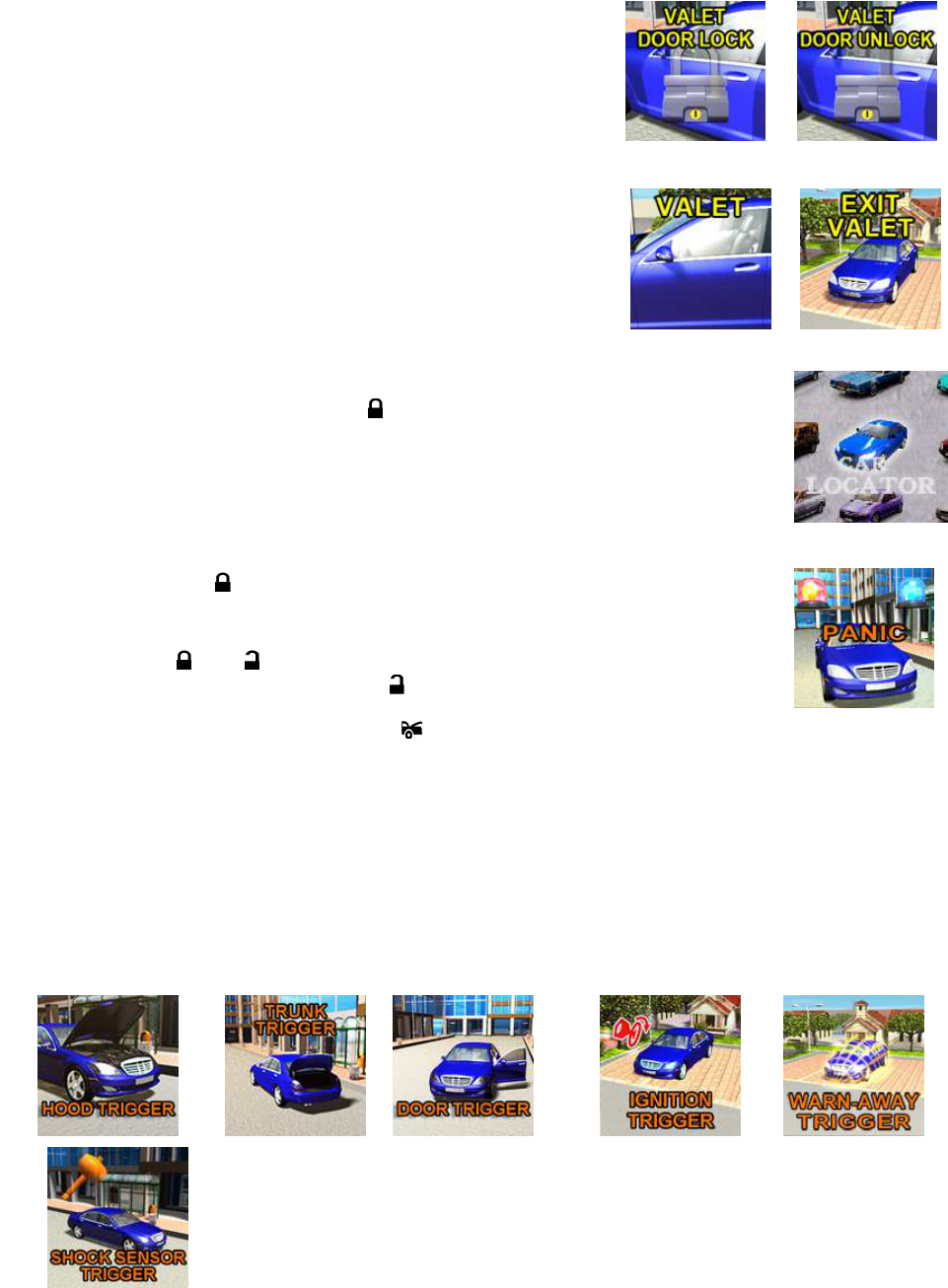
I. VALET MODE:
(System in Disarm or Valet mode)
The valet switch allows you to temporarily bypass all alarm function, eliminating the need to hand your
transmitter to a parking attendants or a garage mechanic.
When the system is in valet mode, all alarm function and remote
start functions
are bypassed, however the remote panic feature
and remote door locks will remain operational. To use the valet
mode, the system must first be disarmed.
Enter Valet Mode:
1.
From the disarmed condition, turn the ignition to the “ON”
position.
2.
Push and hold valet switch for 2 seconds until the LED turns on
solid. The LED will remain on as long as the system is in 'valet
mode'.
Exit Valet Mode:
1. To return to normal operation, turn the ignition 'ON'.
2.
Push and hold valet switch for 2 seconds. The LED will turn off
to indicate the system has exiting the valet mode.
J. CAR LOCATOR
While the system is armed, press the button to activate c
ar locator function. The
siren will chirp 6 times. The parking lights will flash 12 times, for you to easily locate
your vehicle.
K. PANIC FUNCTION:
The transmitter can be used as a remote panic switch to manually trigger the alarm in case emergency.
1. Press and hold the button for 3 second. The alarm will immediately sound
and
the “Panic” icon will display on the OLED screen.
2.
During panic mode, the normal function of this transmitter button will be suspended.
The transmitter and
buttons can be used to lock and unlock the door (if the
option is installed), however once the
button is pressed, the vehicle’s starter
disable device, (where installed) will be enable allowing the vehicle to start.
3. To stop the alarm press the transmitters . The panic mode will be turned off immediately.
4. If the button is not pressed, the alarm will automatically stop after 30 seconds.
L. TRIGGERING THE SYSTEM
When armed, your vehicle is protected as follows:
1.Light impact will trigger the warn-away signal.
2.Heavy impacts / Doors open / Hood open / Trunk open / Turning on the ignition key will trigger the
programmed sequence.
The starter disable relay (if installed) prevents the vehicle’s starter from cranking. The siren, horn, parking
lights, and dome light will turn on to alert of an intrusion for 30 seconds. Then it will stop and automatically
reset and re-arm. If the sensors or detectors are still active, the alarm system will sound a maximum of 6
times of 30 seconds cycles.
Stop The Melody Sound:
While triggering the
alarm the OLE
D screen will alert user through
melody sound and f
lashing trigger icon, press any
button on the OLE
D remote transceiver to stop
melody sound.

Jun/22/2009
RST1000 OP REV.A 15
NOISE ABATEMENT CIRCUIT: Your system has “Noise Abatement Circuit”. It can prevent annoying
repetitive trigger sequences due to faulty door pin switches or environmental condition such as thunder,
jackhammers, airport noise, etc.
Here’s how the “Noise Abatement Circuit” works: If the alarm triggers five times, each time the same
sensor (zone 4) is triggered the “Noise Abatement Circuit” will interpret this pattern of triggers as false
alarms. After the fifth trigger, the “Noise Abatement Circuit” ignores, or bypasses that sensor until any other
sensor or switch is triggered.
“Noise Abatement Circuit” covers doors (Hood/Trunk) differently: If the alarm is triggered by an open door
for six full cycles, the doors will be bypassed until the trigger ceases.
M. ANTI CAR- JACKING
Warning: If you don't need the car jacking function in this alarm system, be sure to set car jacking feature
“OFF”. This system is default setting all car-jacking “OFF”.
ACTIVE ANTI CAR JACKING:
1. Spin up the
switch to the page
1
and then press and hold the “Car Jacking”
button for 2 seconds or press and hold the transmitter and buttons at the
same time for 2 seconds while the vehicle’s ignition is ON. The parking lights will
turn on for 1.5 seconds to indicate the system has entered the car-jacking mode.
2. Once the system is in car-jacking mode and you are forced from the vehicle, the
system will be triggered when the door is opened and closed while the ignition is in
the “ON” position.
PASSIVE ANTI CAR- JACKING:
(Programmable)
1. Turn the ignition switch to the “ON” position. The system enters the car-
jacking
mode.
2. Once the system is in car-jacking mode and you are forced from the vehi
cle, the
system will trigger when the door is opened and closed while the ignition is in the
“ON” position.
TRIGGER THE ANTI CAR -JACKING MODE:
a). 50 seconds after the system has beer triggered. The siren will start chirping for 15 seconds.
b). During this 15 seconds period of chirping, you will be alerting to push the valet switch once to turn off
the car-jacking feature. If not, it will enter second timer car jacking.
c). 65 seconds after the system has beer triggered. The siren starts alarming and the parking light starts
flashing. (Forced engine shutdown mode is activated (if installed), the vehicle will slowly shutdown
within 25 seconds.)
d). 90 seconds after the system has beer triggered
1. The siren still alarming and the parking light flashing, and
2. The starter disable will activate to prevent the vehicle from starting.
3. It will remain active until the vehicle's battery power exhausted.
OVERRIDE THE SYSTEM TO TURN OFF ANTI CAR- JACKING:
Turn the ignition switch from OFF to ON, and within 10 seconds push valet switch, the siren will stop and
the system disarmed
Note: If you use password pin code to double protect the vehicle security, you will need to use it to
completely disarm the system.
N. SYSTEM’S TRIGGER CHECK
Spin up the
switch to the page
4
and then press the “Trigger
Check” button. The remote will respond with one melody sound
and all trigger records will immediately be displayed on the OLED
screen.
Note: It will display the homepage if there were no system’
s
triggered.
O. SYSTEM’S STATUS CHECK
Spin up the
switch to the page
4
and then press the “Status
Check” button. The remote will respond with one melody sound
and the vehicles status will immediately be displayed on the OLED
screen.
Note: It will display the home page if the car’s status is normal.
P. DRIVER PAGING / LOSE & FOUND
It is useful the event that someone wants to page the driver of the parked vehicle or someone cannot find
his OLED remote transceiver.
Jun/22/2009
RST1000 OP REV.A 16
Indoor Driving Paging
If the ignition switch is in
the “off” position, press and hold the valet switch for 2
seconds to page the driver. One chirp sound shall be emitted from the vehicle and the
paging melody will sound from your Remote OLED transceiver. “DRIVER PAGING
”
indication will flash on the OLED screen.
Q. DOME LIGHT CONVENIENCE DELAY & SUPERVISION
The alarm with a unique feature which will turn on your vehicle dome light as following:
1. Upon disarming, the interior light will remain on for 30 seconds.
2. If the vehicle is intruded, the interior light will flash for the same duration as the siren.
Note: Turn on the ignition switch or arm the alarm will turn off the dome light.
R. IGNITION CONTROL DOOR LOCK/UNLOCK.
If the vehicles door locks have been interfaced to the security system, the system will automatically lock the
vehicle's doors when the ignition is turned “ON” and /or unlock the vehicle’s doors when the ignition is
turned “OFF”.
S. TRUNK RELEASE (CHANNEL 3) OUTPUT.
Press and hold button on the transmitter for three seconds to remotely control the
trunk release or other electric devices.
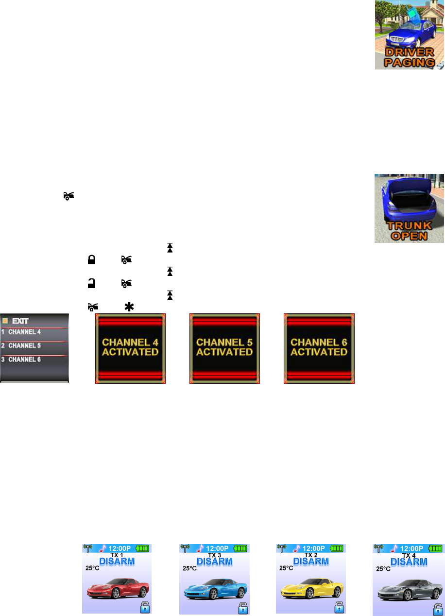
T. CHANNEL 4/5/6 TIMER CONTROL OUTPUT
Activate The Channel 4: Spin up the
switch to the page
3
and then press the “Channel 4” button or
press the transmitter and buttons at the same time to active Channel 4 function.
Activate The Channel 5: Spin up the
switch to the page
3
and then press the “Channel 5” button or
press the transmitter and buttons at the same time to active Channel 5 function.
Activate The Channel 6: Spin up the
switch to the page
3
and then press the “Channel 6” button or
press the transmitter and buttons at the same time to active Channel 6 function.
U. MULTI- VEHICLE SECURITY OPREATION:
Your remote transmitter can be utilized to control multi- vehicle security system, to program the remote
control transmitter to a second vehicle, follow the instructions for Transmitter programming. All
programming parameters will be the same except for the following:
For Regular Remote Control Transmitter:
1. Prior to pushing any button on the transmitter. Press the Select
II
IIII
II
button first on the transmitter.
2. Once
II
IIII
II
button is pressed the LED on the transmitter will illuminate for 3.5 seconds to indicate the
second transmitter pin code is ON.
3. While the LED is illuminated, press any button on the remote control transmitter to control a second
vehicle security system.
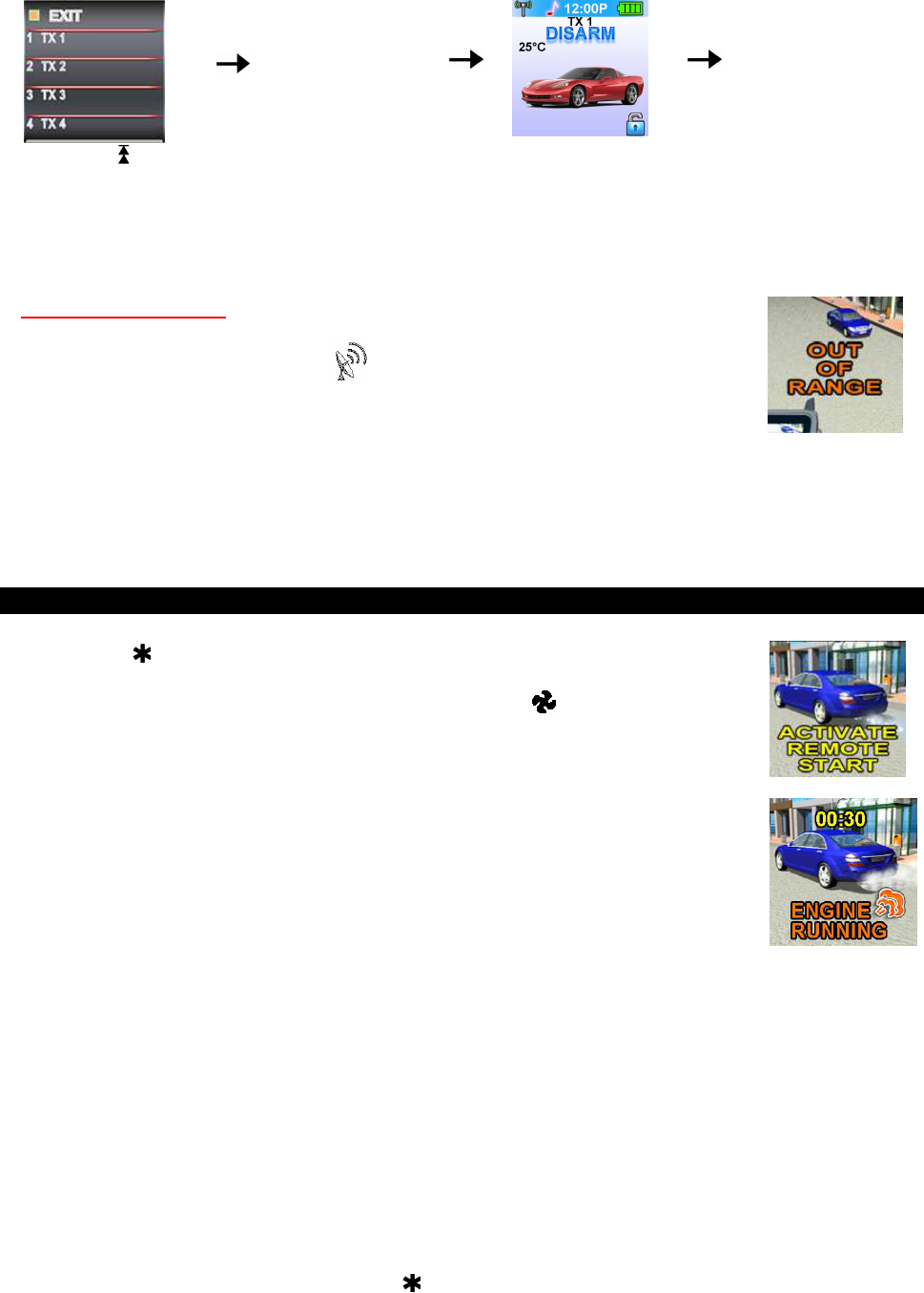
For 2-way OLED Remote Control Transceiver:
A maximum of
four vehicle’s
security
systems can be
controlled by
this transceiver.
TX1
TX2
TX3
TX4
Jun/22/2009
RST1000 OP REV.A 17
Spin up the switch
to the page 6
The four transmitters will
be display on the OLED
screen, you can select
one of them through
your hand hold unit.
Press the button 3 and
the setting is done also
the “
TX 3”
will display
on the OLED screen
Now you can press
button to remote control
The “
TX 3 “
vehicle’s
security system.
V. OUT OF RANGE AND TEMPERATURE INDICATION:
If this feature is selected, the system will automatically check the range and update
the temperature every 33 minutes.
1. If the user is within the range, the icon will display on the OLED screen.
2. If the user is out of range, the remote will have five short “bi” sounds and the “Out
Of Range” icon will appear on the OLED screen.
Note: Programming “Out Of Range and Temperature Indication” will decrease the life
expectancy of the battery.
W. POWER ON MEMORY:
This security system is equipped with circuitry that will allow the unit to remember its alarm state if the
power is lost and then reconnected.
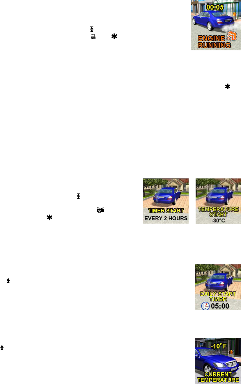
REMOTE START OPERATION:
A. TO REMOTE START THE VEHICLE:
1. Press the button on the transmitter. Twice if safety start has been programmed.
2. The parking light will activate to indicate the remote start received the signal. (A
melody sound from your Remote OLED transceiver and “
” icon will flash on the
OLED screen to confirm the remote start was activated.)
3. The engine will start in approximately 5 seconds.
4. Once the engine is running, after the parking lights will turn on again
and your
climate controls will activate and adjust the vehicles interior temperature to your
Preset setting. (While the vehicle is running, the “Engine Running
” icon and the
“minutes” digit on the OLED screen will flash. It will indicate a count down ti
mer
based on the 5, 10, 20 or 30 minute run time set up by your installation center.)
5. The vehicle will run for a 5 to 3
0 minute cycle and automatically shut down. (When
the unit shuts off the count down timer will turn off and the transmitter will play
a
melody.)
Note: The Remote Start Unit will not start the vehicle if any one of the following
conditions exists:
1. The hood is opened.
2. The brake pedal is pressed.
3. Move the optional remote start enable toggle switch to OFF position. (If installed)
4. The gear selector is in any gear other then “PARK” or “NEUTRAL”
B. TO OPERATE THE VEHICLE WHILE RUNNING ON THE REMOTE START:
To operate the vehicle while engine running on the remote start.
1. Insert the ignition key and turn it to “ON” (not the start) position.
2. Press the brake pedal.
Note: If the brake pedal is pressed before the key is in the ON position, the engine will shut down.
C. TEMPORARY STOP FEATURE:
This feature allows the vehicle to remain running after the key has been removed from the ignition. This
feature is useful for occasions when you wish to exit and lock the vehicle for short periods of time, but
would like to leave the motor running and the climate control on.
1. Before turning off the engine, press the button on the transmitter. Twice if safety start has been
programmed. The LED indicator will flash 3 times to confirm.
2.Turn the ignition key to OFF position. (The engine will stay running.)
3.The engine will run until the pre-programmed time elapsed or a shutdown input is received.
D. TURBO TIMER MODE:
(Factory defaults setting at active turbo timer mode.)
Jun/22/2009
RST1000 OP REV.A 18
Turbo timer
mode keeps the engine running after arriving at your destination for a
programmable period of 1, 3 or 5
minutes. This allows the system time to conveniently
cool down the turbo after you have left the vehicle. To activate the turbo timer:
1. While engine is running, place the transmission gear in the park position and pull up
the hand brake.
2. Before turning off the engine, Spin up the
switch to the page
5
and then
press
the “Turbo Start” button or press and release and buttons at the same time.
-- The parking light will activate to indicate the remote start has entered turbo timer mode. --
3. Pull out the “Ignition Key” from the key cylinder.
-- The engine will continue to run. --
4. Exit and secure the vehicle.
-- Engine continues running until the pre-programmed time has elapsed. --
If you do not want the vehicle to continue running, simply step on the vehicle's brake, or activate the
button in succession. Any of these will cause the engine to turn off.
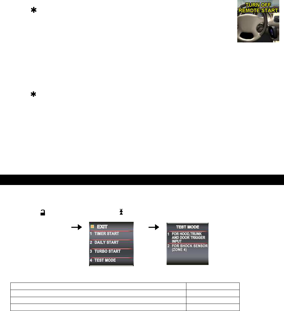
E. TIMER START:
Your system has the ability to automatically start the vehicle every 1,2 or 3 hours, run for the
pre-programmed time (10, 20, 30 or 60 minutes), and then shut off. This will continue for 48 hours. This
feature is especially useful in cold climates where the only means to keep the engine and engine fluids
warm is to periodically start the engine.
If the system is set up to start in temperature mode, the system can be programmed to automatically start
the vehicle engine whenever the temperature inside the vehicle reaches or drops below the
preprogrammed temperature level. The system will monitor the air temperature every 3 (2 /1) hour and will
only start the engine during extreme cold temperatures.
WARNING! Be certain that the vehicle is outdoors before using this or any remote vehicle-starting device.
A running engine produces dangerous carbon monoxide fumes, which can be harmful or fatal if prolonged
exposure occurs. DO NOT remote start the vehicle if it is garaged.
Timer Start Operation:
1. Turn the ignition key on then off. Within 15 seconds …..
2-a. For 2-Way Transceiver: Spin up the
switch to the page 5
and then press the “Timer Start” button. or
2-b. For Regular one-way Transmitter: Press the button
first,
with 3 seconds press the button.
3. The parking lights will flash and the siren will chirp 3 times indicating the timed start mode has been
activated.
Daily Timer Start Operation: The feature is very useful for the driver who wants to run the vehicle
punctually at the same time next morning. Before set-up of the “Daily Timer Start”, you should set you time
Engine start time (See the “Daily Start Timer” Setting on page 10)
1. Turn the ignition key ON then OFF. Within 15 seconds …..
2. Spin up the switch to the page 5 and then press the “Daily start” button.
3. The parking lights will flash and the siren will chirp 6 times indicating the daily timed
start mode is activated.
Cancel the timer start: To cancel the timer start do one of the following:
1. Start the vehicle manually with the use of the ignition key.
2. Remote start the vehicle using your keychain RF transmitter.
G. TEMPERATURE CHECK
You can monitor the present indoor temperature
of the passenger compartment
through the OLED screen, before cooling or heating your vehicle.
Spin up the
switch to the page
4
and then press the “Monitor TEMP.” button
; the
in-door temperature will be shown on the OLED screen. This reading may be highe
r
than actual ambient temperature due to the greenhouse effect and is relative only to
the inside vehicle temperature.
H. TO TURN OFF THE REMOTE START:
Jun/22/2009
RST1000 OP REV.A 19
When the engine is running by remote start and you want to stop it,
1. Press button on the remote transmitter while in remote start mode.
2. Move the optional remote start enable toggle switch to OFF position.(If installed)
3. Press the brake pedal.
The vehicle will shut down and turn off the parking light to indicate engine stopped.
I. SHUT-DOWN INPUT FOR REMOTE STARTER:
If any of the following conditions exist while the system is operating, the engine will not start or will shut
down immediately:
1. The hood is opened.
2. The brake pedal is pressed.
3. Engine is over-revved. {“Tachometer checking type” only}
4. The pre-programmed run time (5 /10 /20 / 30 minutes) has elapsed.
5. Press button on the remote transmitter while in remote start mode.
6. Move the optional remote start enable toggle switch to OFF position. (If installed)
7. The vehicle refused to start running after {3} unsuccessful attempts.
J. DISABLING THE REMOTE START SYSTEM:
(If installed)
This feature allows your system’s remote start unit to be temporarily disabled to prevent the vehicle from
being remote started accidentally. This feature is useful if the vehicle is being serviced or stored in an
enclosed area. To disable the remote start, move the optional remote start enable toggle switch to the OFF
position or place the unit in Valet Mode.
TEST MODE
In this test mode, this system can test the all of the trigger input. The installer can save time to test the
sensitivity of the 2-stage shock sensor and optional sensor and without using the traditional
arming/disarming procedures to test the sensors.
1. Press the button
to disarm the system,
within 10 seconds
2.
Spin up the switch to
the page 5
3. Press button 4
4. Press button 1 to test the Trigger and Safety Shutdown Input: One chirp to indicate your are in test mode
Trigger sensor Siren short chirps
Zone 2 / Trunk trigger (H3/1 Dark Blue wire) 2
Zone 3 / Door trigger (H3/2 Dark Green or H3/3 Violet wire) 3
5. Press button 2 to test the Two Stage Shock Sensor: Two chirps to indicate your are in the two-stage
shock sensor test mode.
1. Activate the warn-away (first stage of the shock sensor); system will emit a short chirp.
2. Activate the full alarm (second stage of the shock sensor); system will emit a long chirp.
3. Continue to test the shock sensor until you reach the proper sensitivity.
Federal Communication Commission Interference Statement
This equipment has been tested and found to comply with the limits for a Class B
digital device, pursuant to Part 15 of the FCC Rules. These limits are designed to
provide reasonable protection against harmful interference in a residential installation.
This equipment generates, uses and can radiate radio frequency energy and, if not
installed and used in accordance with the instructions, may cause harmful interference
to radio communications. However, there is no guarantee that interference will not
occur in a particular installation. If this equipment does cause harmful interference to
radio or television reception, which can be determined by turning the equipment off
and on, the user is encouraged to try to correct the interference by one of the
following measures:
. Reorient or relocate the receiving antenna.
. Increase the separation between the equipment and receiver.
. Connect the equipment into an outlet on a circuit different from that to which the
receiver is connected.
. Consult the dealer or an experienced radio/TV technician for help.
FCC Caution :To assure continued compliance, any changes or modifications not
expressly approved by the party responsible for compliance could void the user's
authority to operate this equipment. (Example - use only shielded interface cables
when connecting to computer or peripheral devices).
FCC Radiation Exposure Statement
This device complies with Part 15 of the FCC Rules. Operation is subject to the
following two conditions:
(1) This device may not cause harmful interference, and (2) This device must accept
any interference received, including interference that may cause undesired
operation.
To satisfy FCC RF exposure compliance requirements, this device should be used in
hand-held, hand-operated configurations only. The device and its antenna must
maintain a separation distance of 20cm or more from a person’s body, except for the
hand and wrists, to satisfy RF exposure compliance.
This device is designed to be used in a person’s hands and its operating configurations
do not support normal transmissions while it is carried in pockets or holsters next tot a
person’s body.