Advanced Card Systems ACR330 ACR330 Validator with QR Code Scanner User Manual ACR330 V1 00
Advanced Card Systems Limited ACR330 Validator with QR Code Scanner ACR330 V1 00
UserManual.wiki
>
Advanced Card Systems
>
ACR330 User Manual
User Manual
Navigation menu
Upload a User Manual
Namespaces
Wiki Guide
HTML
PDF
Info
Views
User Manual
Discussion / Help
Navigation

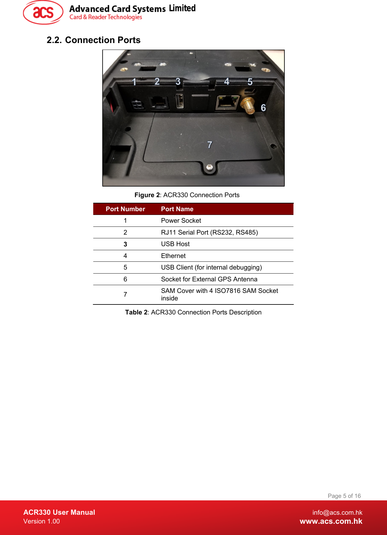
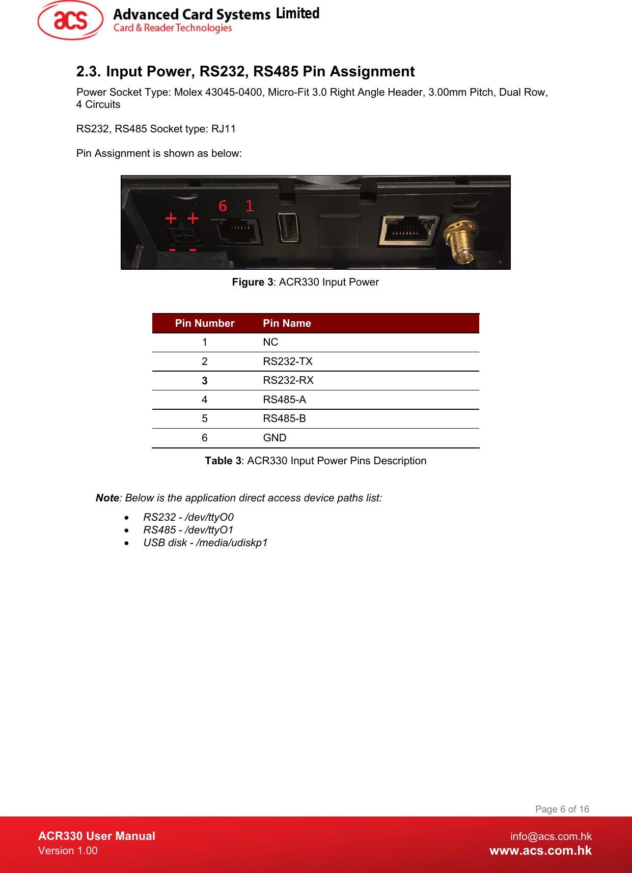
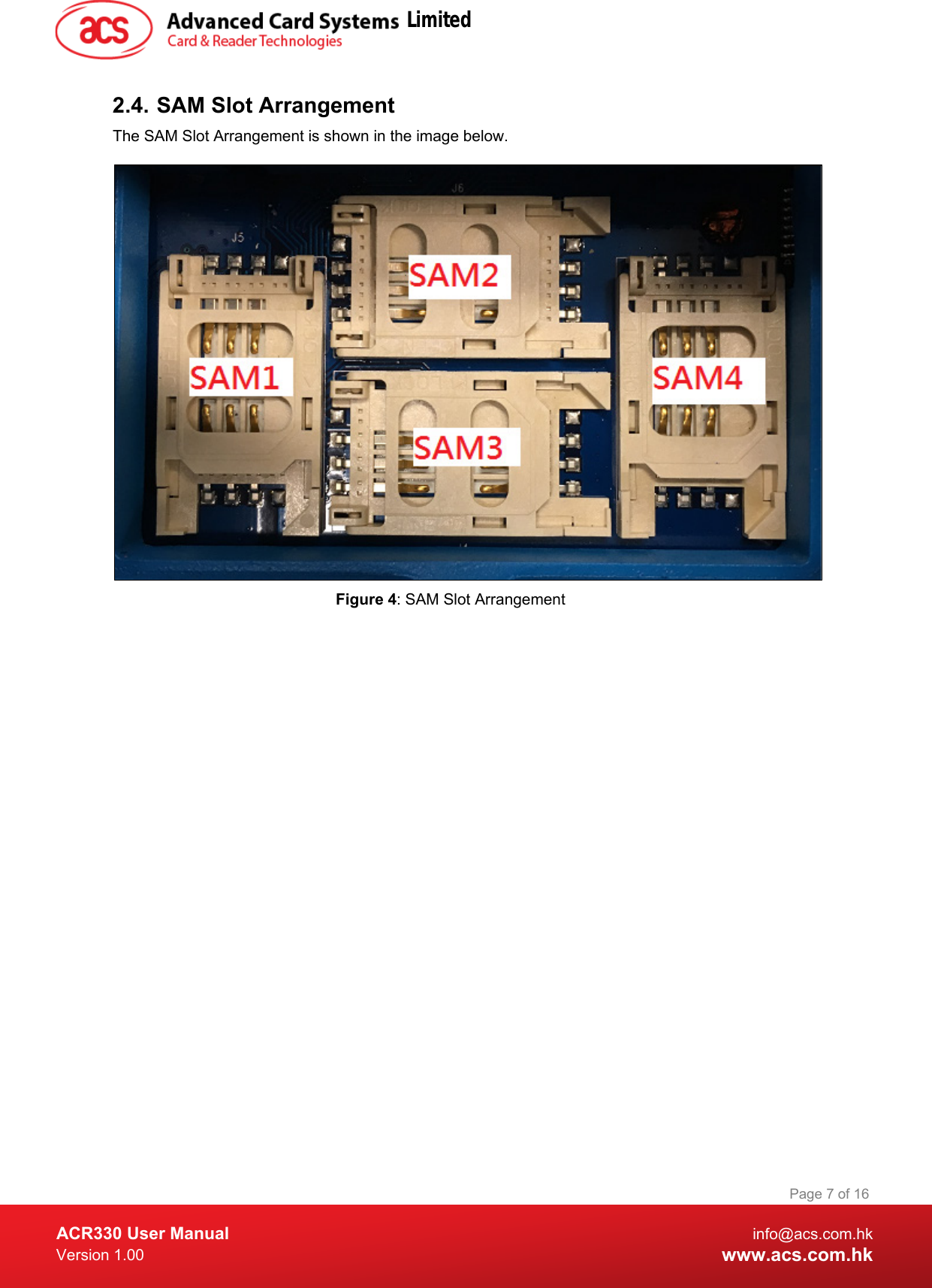
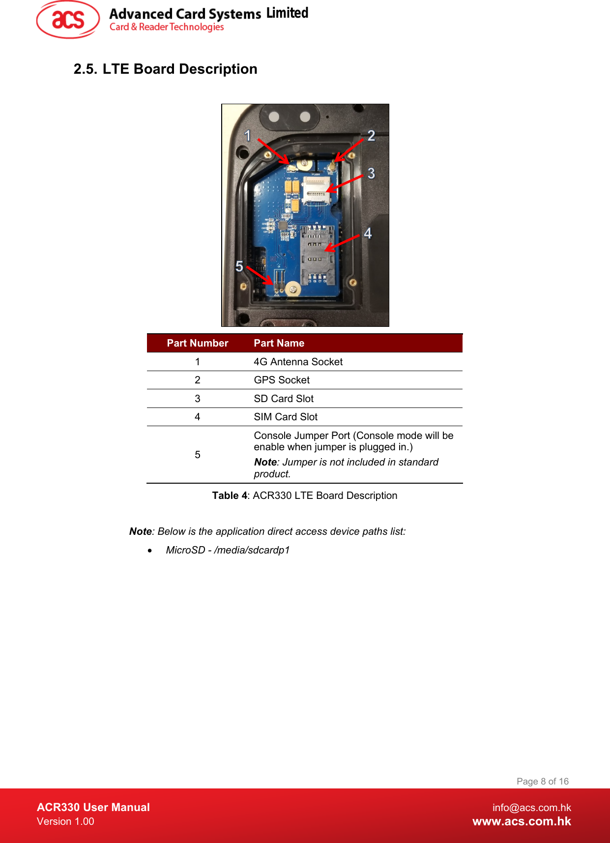
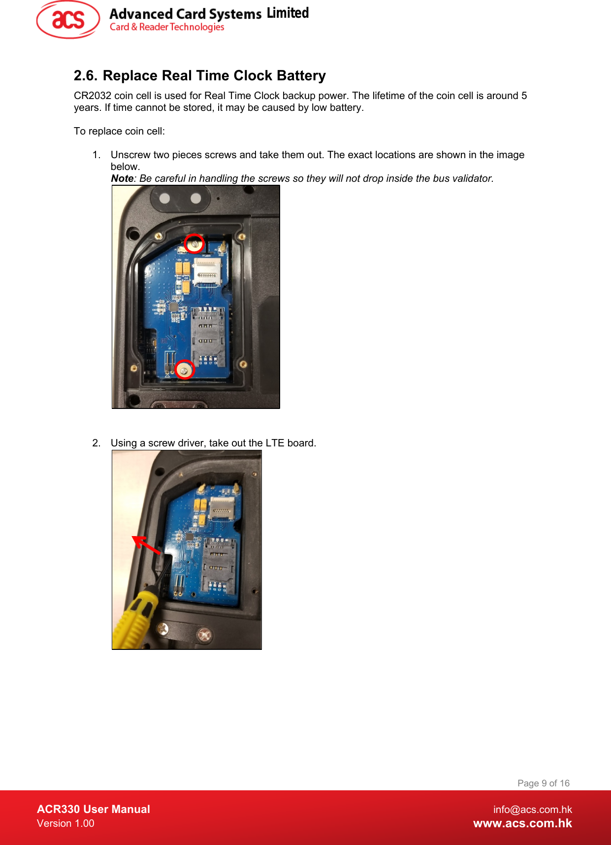
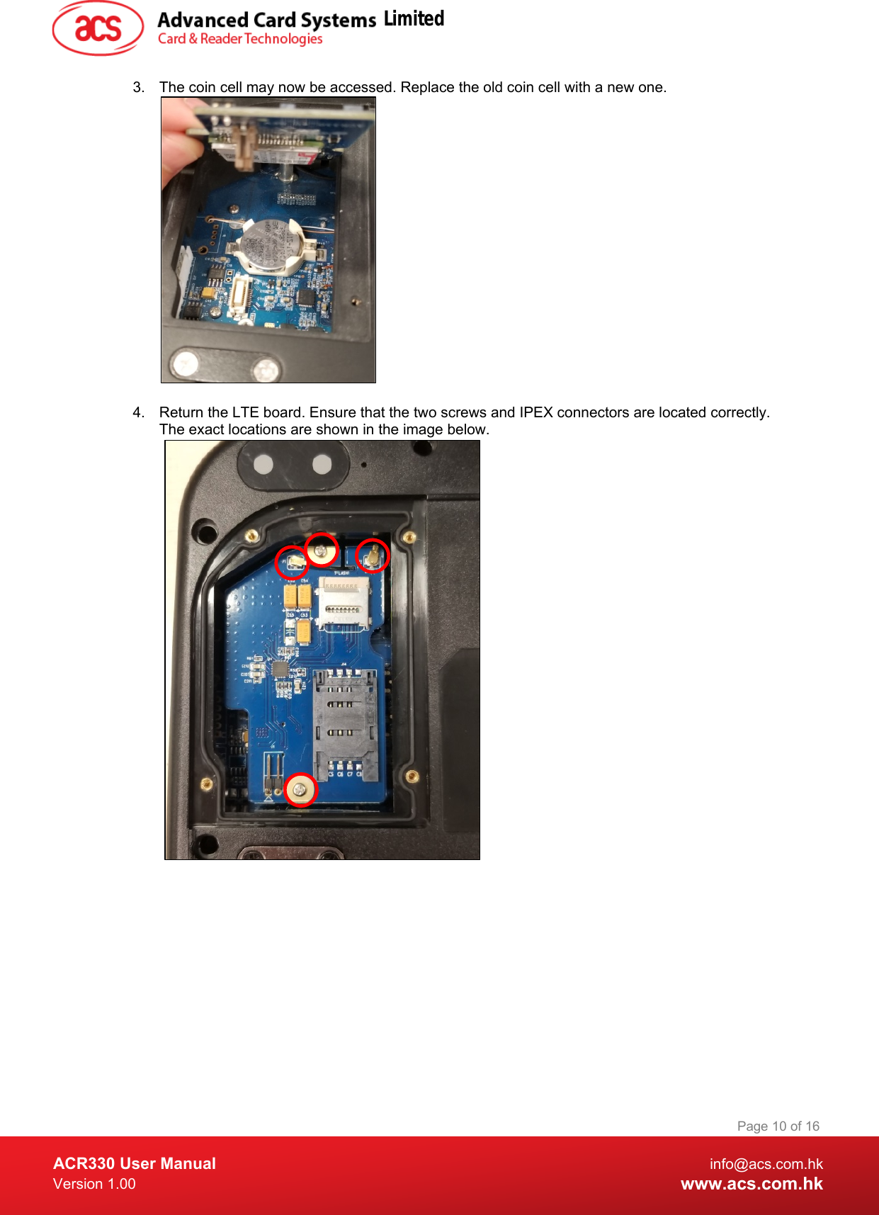
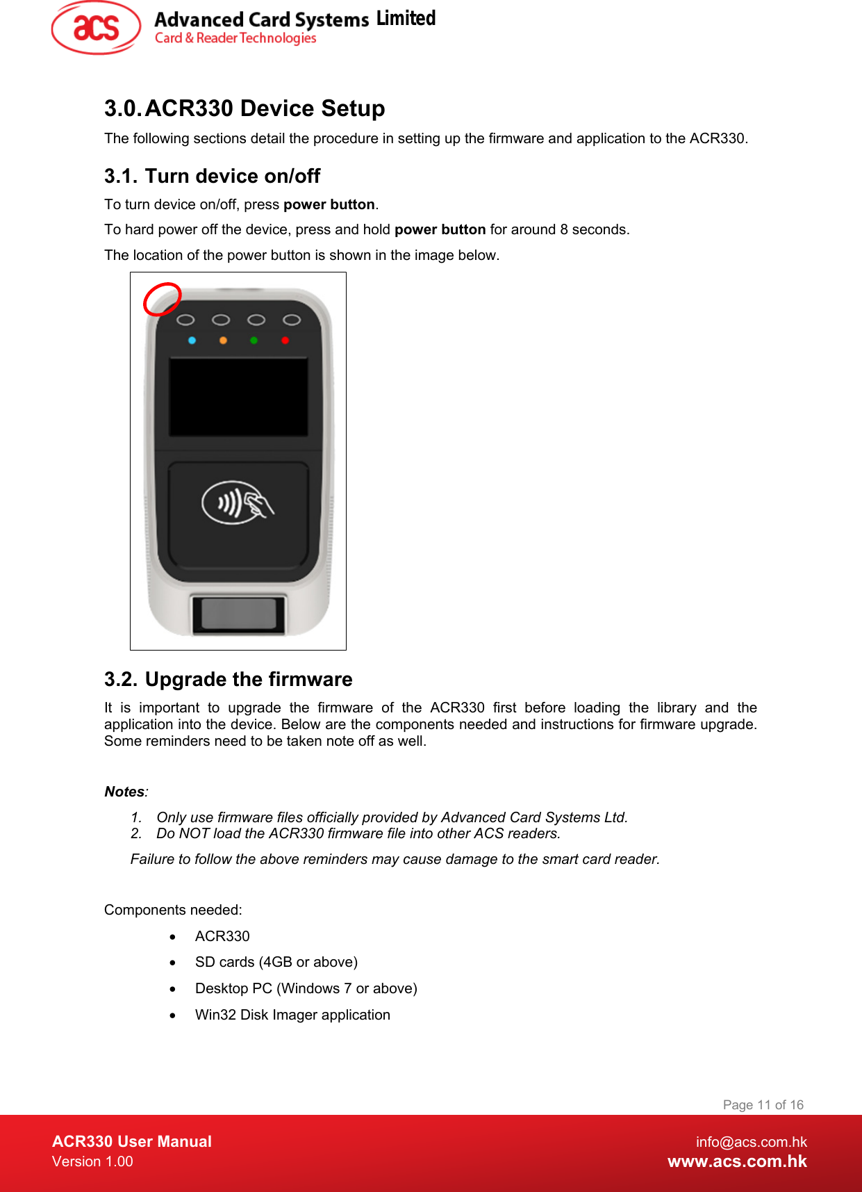
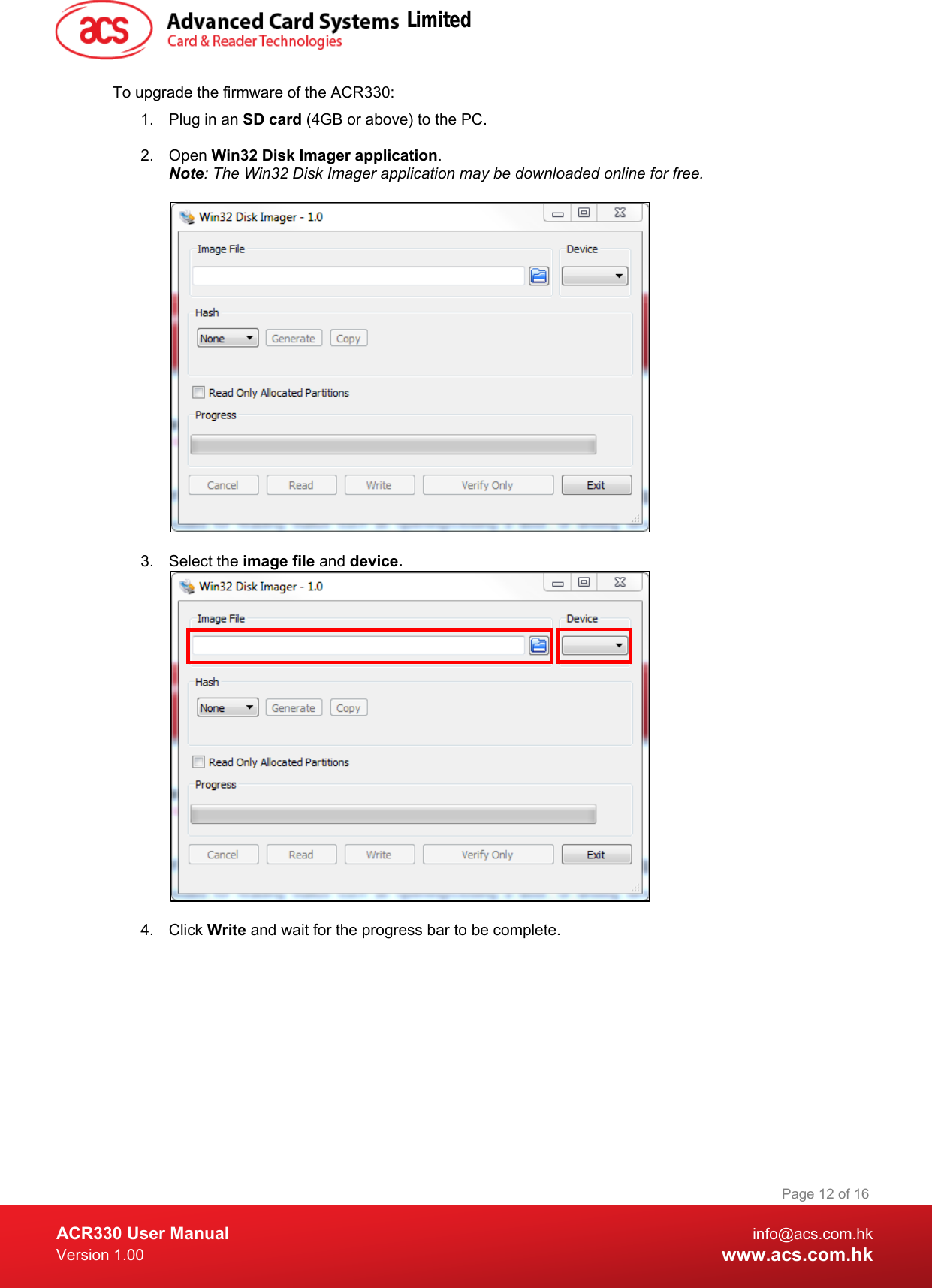
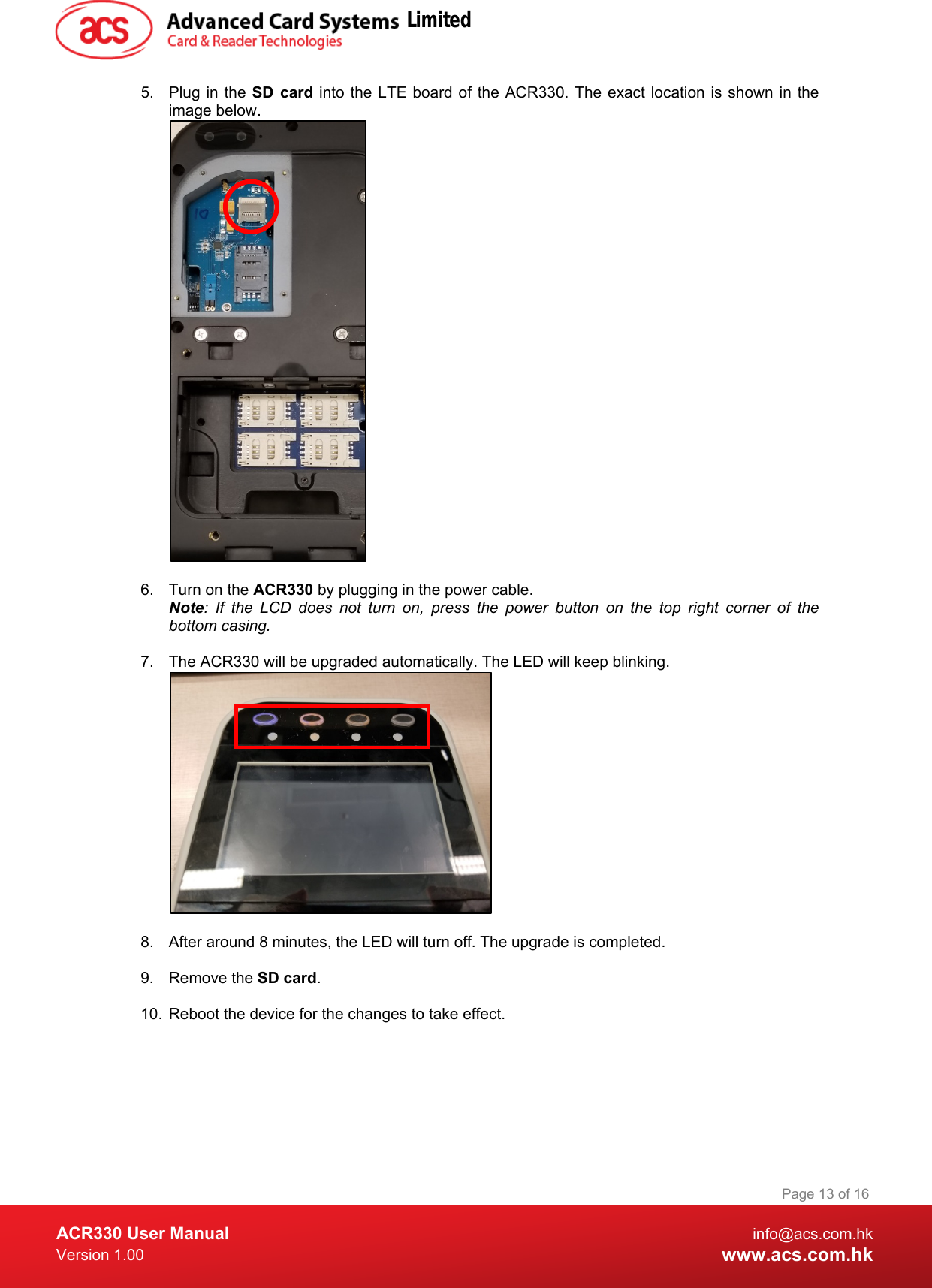
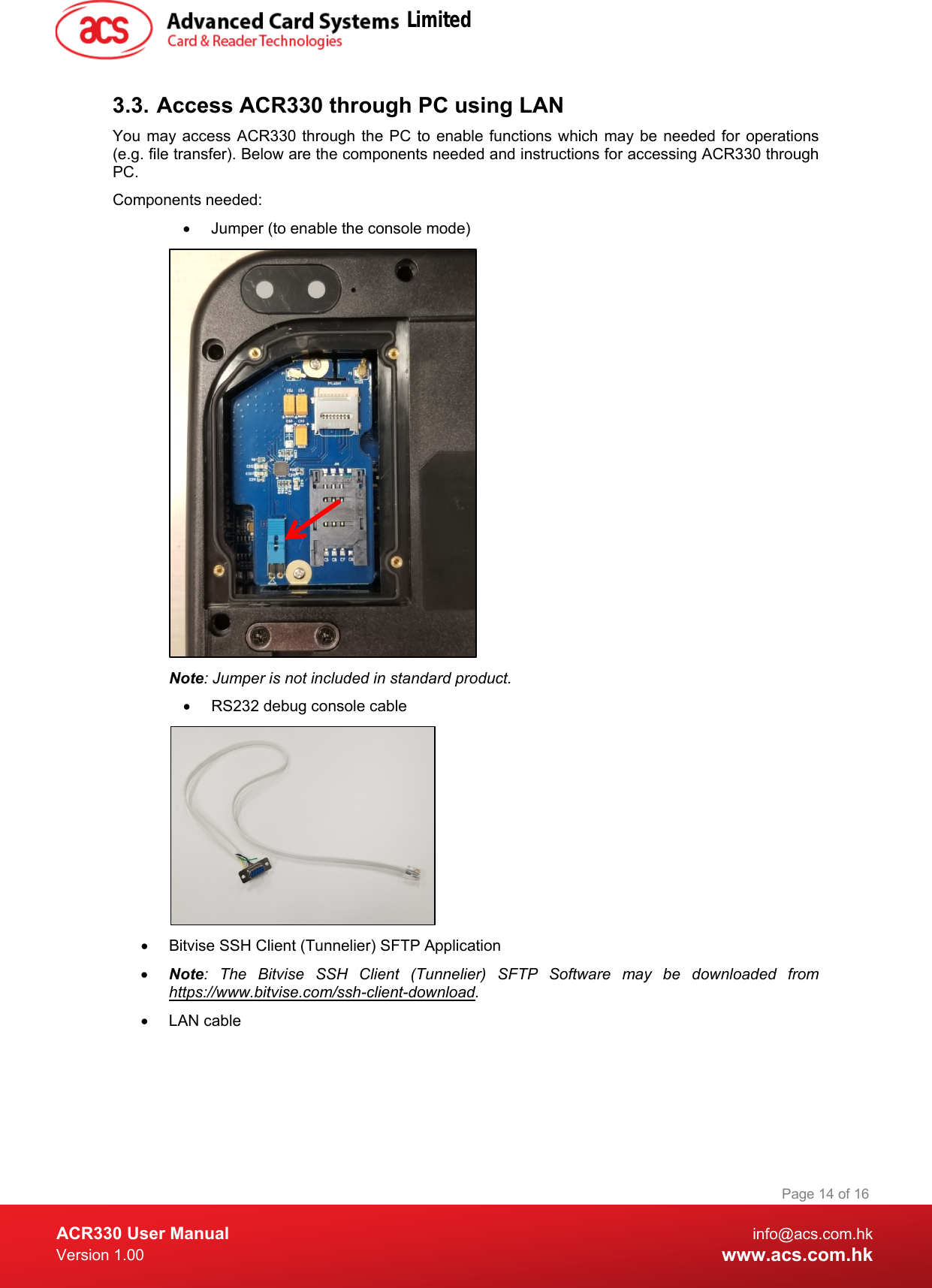
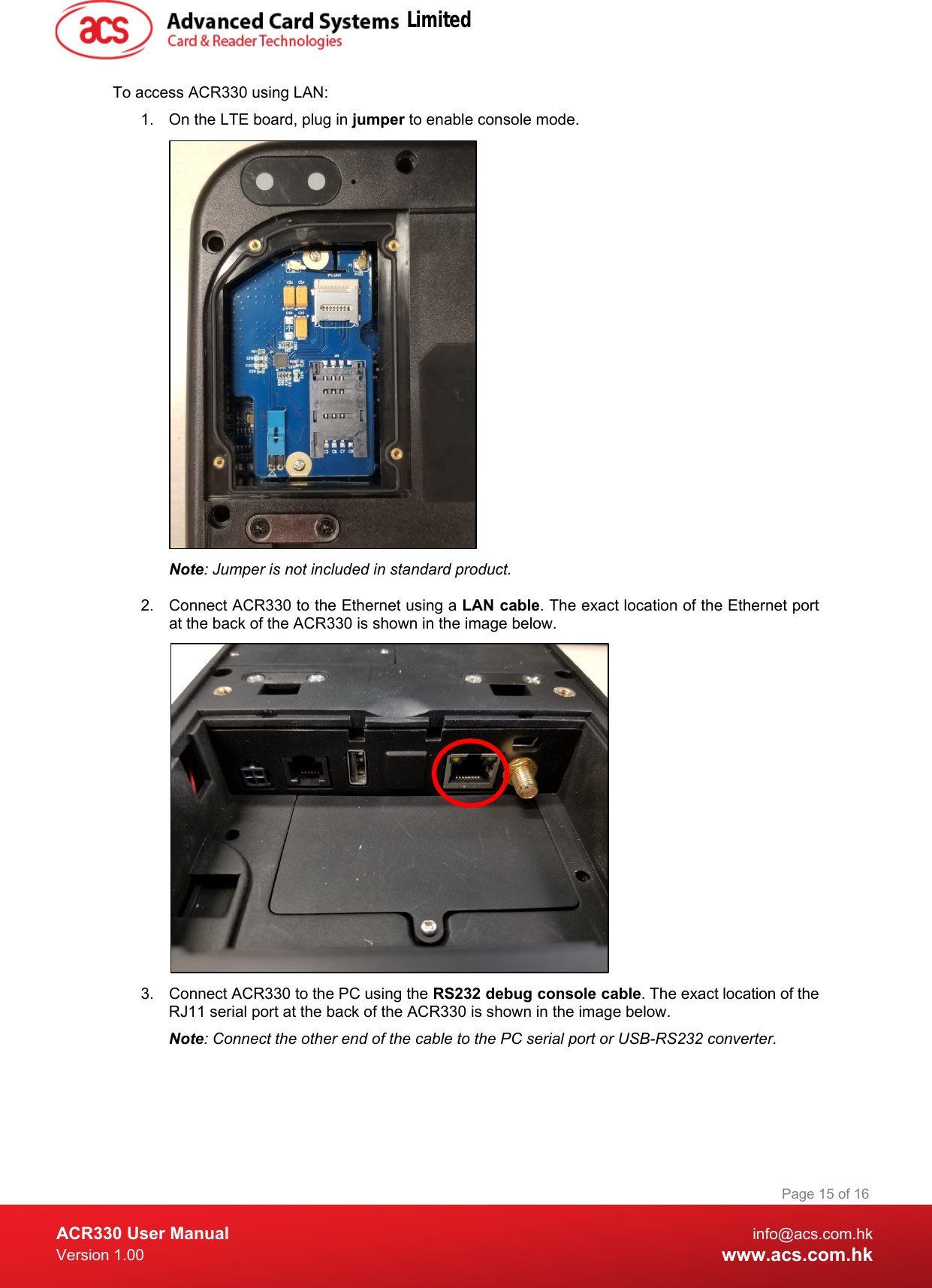
![ACR330 User Manual info@acs.com.hk Version 1.00 www.acs.com.hk Page 16 of 16 4. Turn on the ACR330. 5. Login in to the console. a. Login name: root b. Password: root Note: If [root@Linux/root] # is shown, it means login is successful 6. Type “ifconfig eth0” to get IP address. 7. Open the Bitvise SSH Client (Tunnelier) SFTP Application on the PC. 8. Login with the IP address in step 5. a. Login name: machinekit b. Password: machinekit 9. The ACR330 may now be accessed on the PC. Note: For more details, please refer to ACR330 API.chm. Limited](https://usermanual.wiki/Advanced-Card-Systems/ACR330/User-Guide-4104545-Page-16.png)