Advanced Card Systems ACR330 ACR330 Validator with QR Code Scanner User Manual ACR330 V1 00
Advanced Card Systems Limited ACR330 Validator with QR Code Scanner ACR330 V1 00
User Manual
Subject to change without prior notice info@acs.com.hk
www.acs.com.hk
User Manual V1.00
ACR330
Bus Validator II
Limited

ACR330 User Manual info@acs.com.hk
Version 1.00 www.acs.com.hk
Page 2 of 16
Table of Contents
1.0. Introduction ............................................................................................................... 3
2.0. ACR330 Overview ..................................................................................................... 4
2.1. Parts Description ................................................................................................................... 4
2.2. Connection Ports ................................................................................................................... 5
2.3. Input Power, RS232, RS485 Pin Assignment ....................................................................... 6
2.4. SAM Slot Arrangement .......................................................................................................... 7
2.5. LTE Board Description ........................................................................................................... 8
2.6. Replace Real Time Clock Battery .......................................................................................... 9
3.0. ACR330 Device Setup ............................................................................................. 11
3.1. Turn device on/off ................................................................................................................ 11
3.2. Upgrade the firmware .......................................................................................................... 11
3.3. Access ACR330 through PC using LAN .............................................................................. 14
List of Figures
Figure 1 : ACR330 Parts ........................................................................................................................ 4
Figure 2 : ACR330 Connection Ports ..................................................................................................... 5
Figure 3 : ACR330 Input Power ............................................................................................................. 6
Figure 4 : SAM Slot Arrangement .......................................................................................................... 7
List of Tables
Table 1 : ACR330 Parts Description ....................................................................................................... 4
Table 2 : ACR330 Connection Ports Description ................................................................................... 5
Table 3 : ACR330 Input Power Pins Description .................................................................................... 6
Table 4 : ACR330 LTE Board Description .............................................................................................. 8
Limited

ACR330 User Manual info@acs.com.hk
Version 1.00 www.acs.com.hk
Page 3 of 16
1.0. Introduction
The ACR330 Bus Validator is designed specifically for the Automatic Fare Collection (AFC) system, to
offer the convenience of cashless payment in buses, ferries, trams, railways and other transportation
modes.
ACR330 enables high-speed transaction processing and transaction records collection through 13.56
MHz contactless (RFID) technology. It supports all smart cards/tags compliant to ISO 14443 Type A &
B, Felica and MIFARE®. Through GPS, it enables to locate vehicles, manage fleets and set flexible
distance-based fares.
An embedded barcode scanner allows transaction through print out or mobile barcodes. It supported
various advanced connection modes for data transfer which includes Wi-Fi, 3G/4G and GSM/GPRS.
The mobile validator supported multiple payment transactions as a means of propriertary use that
consists of four payment system certifications that caters to both Visa PayWave and MasterCard.
The purpose of this document is to provide a detailed guide on how to use the ACR330.
Limited
ACR330 User Manual info@acs.com.hk
Version 1.00 www.acs.com.hk
Page 4 of 16
2.0. ACR330 Overview
2.1. Parts Description
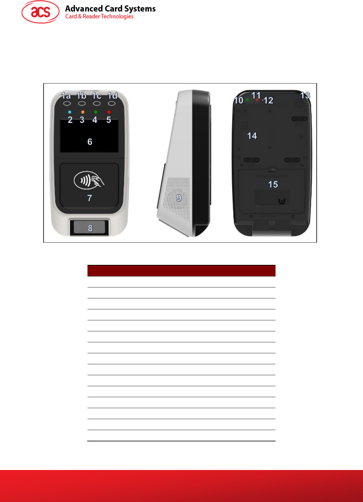
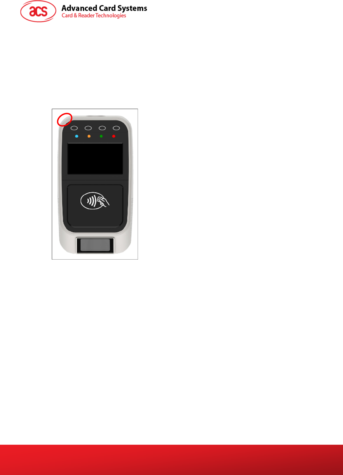
Figure 1: ACR330 Parts
Part Number Part Name
1a, 1b, 1c,1d Programmable Button with Backlight (Blue)
2 Blue LED Indicator (For passenger)
3 Yellow LED Indicator (For passenger)
4 Green LED Indicator (For passenger)
5 Red LED Indicator (For passenger)
6 LCD Display with Touch Panel
7 Tapping Area
8 1D/2D Barcode Scanning Area
9 Speaker
10 Green LED Indicator (For Driver)
11 Red LED Indicator (For Driver)
12 Buzzer
13 Power Button
14 SIM and SD Card Cover
15 Back Cover
Table 1: ACR330 Parts Description
Limited
ACR330 User Manual info@acs.com.hk
Version 1.00 www.acs.com.hk
Page 5 of 16
2.2. Connection Ports
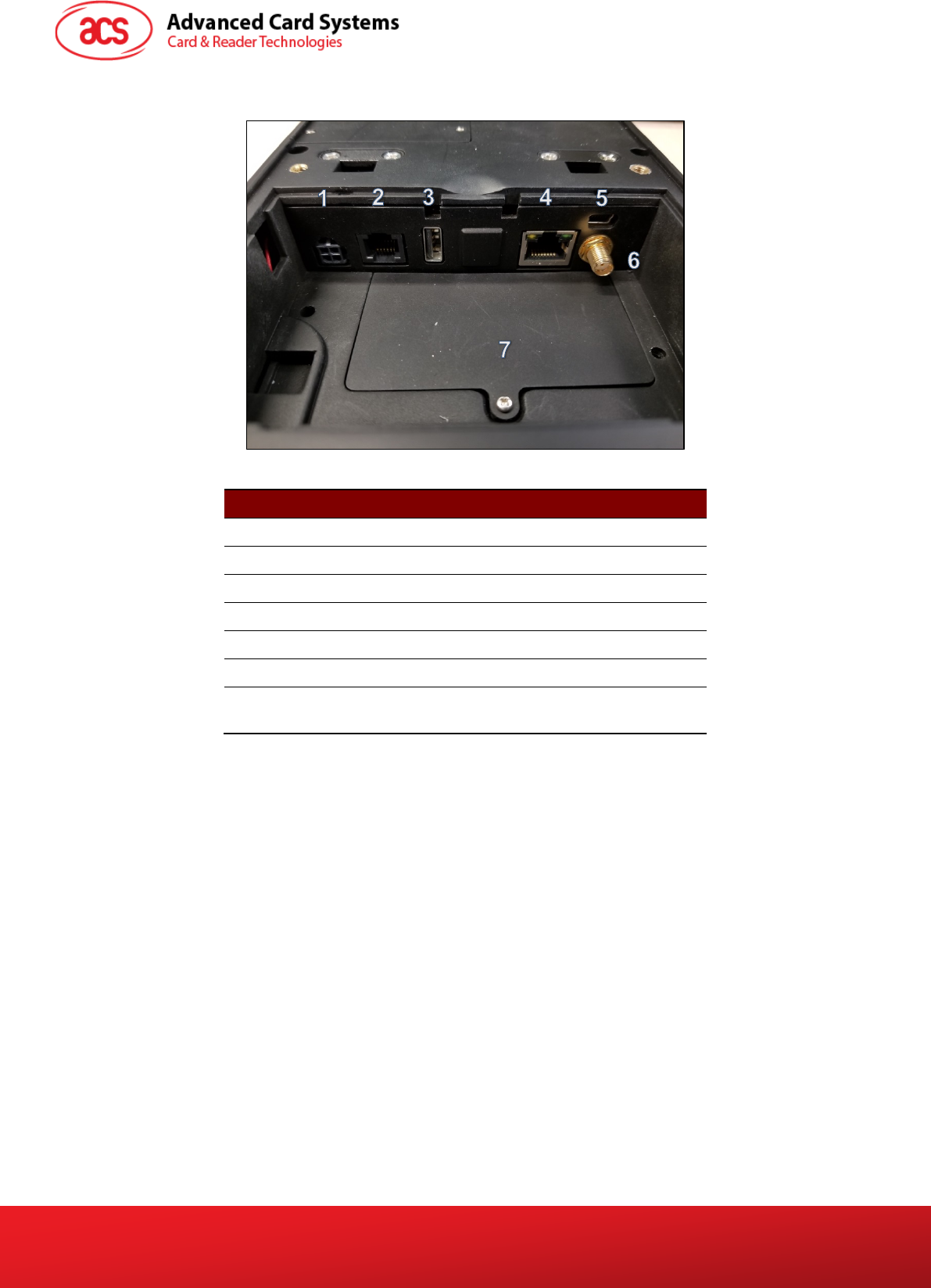
Figure 2: ACR330 Connection Ports
Port Number Port Name
1 Power Socket
2 RJ11 Serial Port (RS232, RS485)
3 USB Host
4 Ethernet
5 USB Client (for internal debugging)
6 Socket for External GPS Antenna
7 SAM Cover with 4 ISO7816 SAM Socket
inside
Table 2: ACR330 Connection Ports Description
Limited
ACR330 User Manual info@acs.com.hk
Version 1.00 www.acs.com.hk
Page 6 of 16
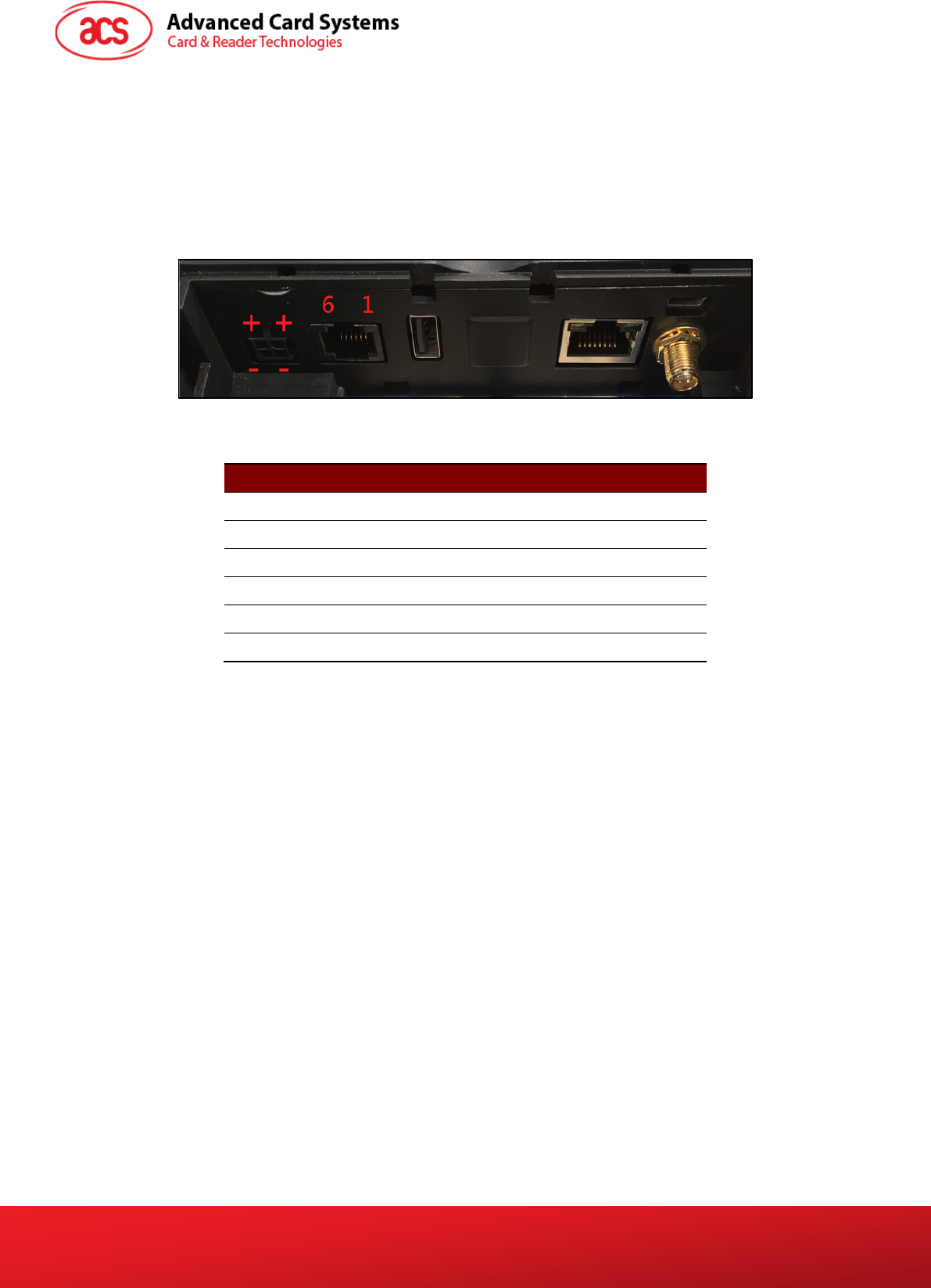
2.3. Input Power, RS232, RS485 Pin Assignment
Power Socket Type: Molex 43045-0400, Micro-Fit 3.0 Right Angle Header, 3.00mm Pitch, Dual Row,
4 Circuits
RS232, RS485 Socket type: RJ11
Pin Assignment is shown as below:
Figure 3: ACR330 Input Power
Pin Number Pin Name
1 NC
2 RS232-TX
3 RS232-RX
4 RS485-A
5 RS485-B
6 GND
Table 3: ACR330 Input Power Pins Description
Note: Below is the application direct access device paths list:
• RS232 - /dev/ttyO0
• RS485 - /dev/ttyO1
• USB disk - /media/udiskp1
Limited
ACR330 User Manual info@acs.com.hk
Version 1.00 www.acs.com.hk
Page 7 of 16
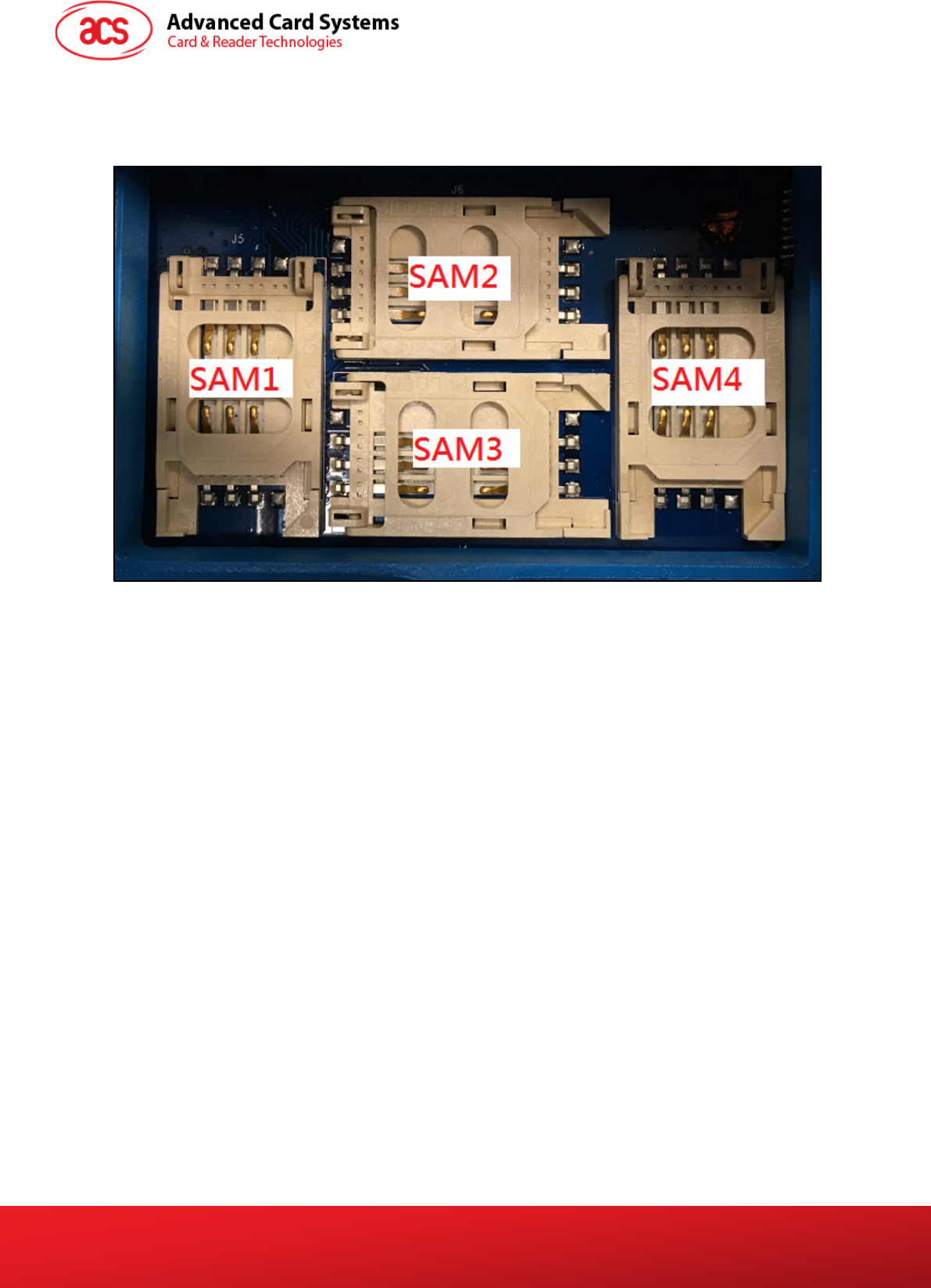
2.4. SAM Slot Arrangement
The SAM Slot Arrangement is shown in the image below.
Figure 4: SAM Slot Arrangement
Limited
ACR330 User Manual info@acs.com.hk
Version 1.00 www.acs.com.hk
Page 8 of 16
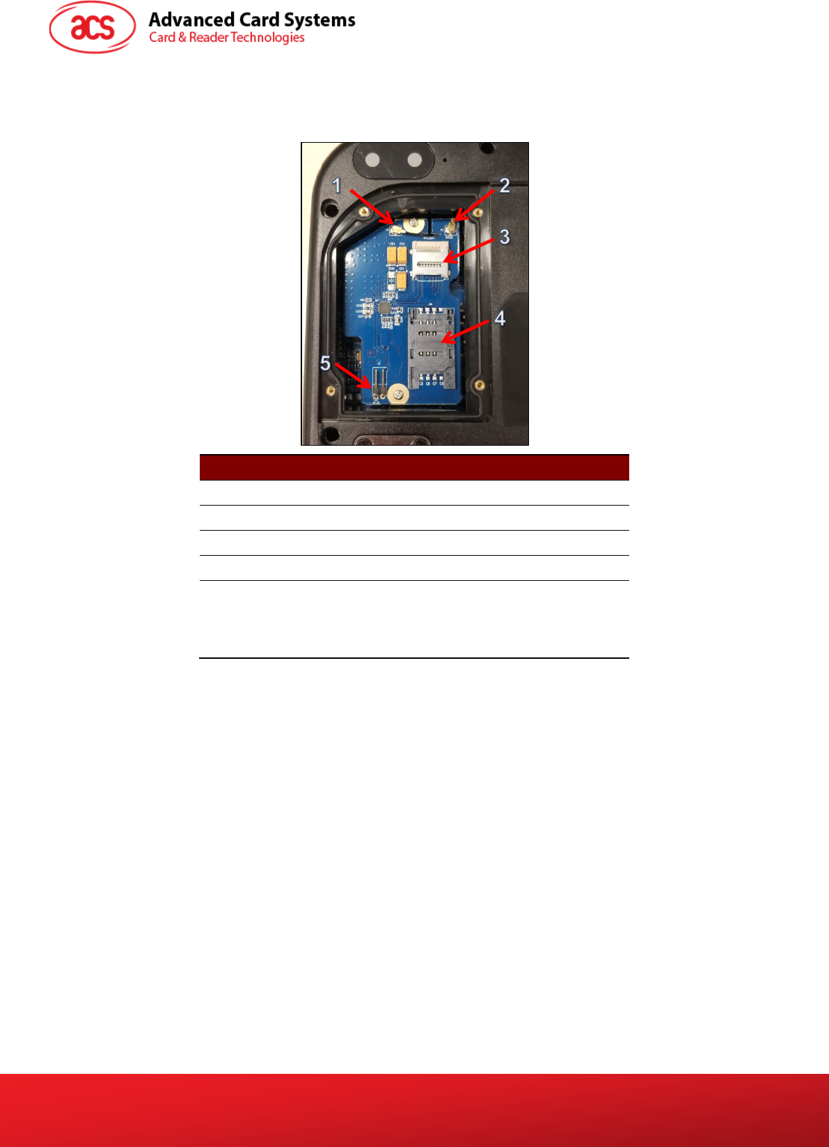
2.5. LTE Board Description
Part Number Part Name
1 4G Antenna Socket
2 GPS Socket
3 SD Card Slot
4 SIM Card Slot
5
Console Jumper Port (Console mode will be
enable when jumper is plugged in.)
Note: Jumper is not included in standard
product.
Table 4: ACR330 LTE Board Description
Note: Below is the application direct access device paths list:
• MicroSD - /media/sdcardp1
Limited
ACR330 User Manual info@acs.com.hk
Version 1.00 www.acs.com.hk
Page 9 of 16
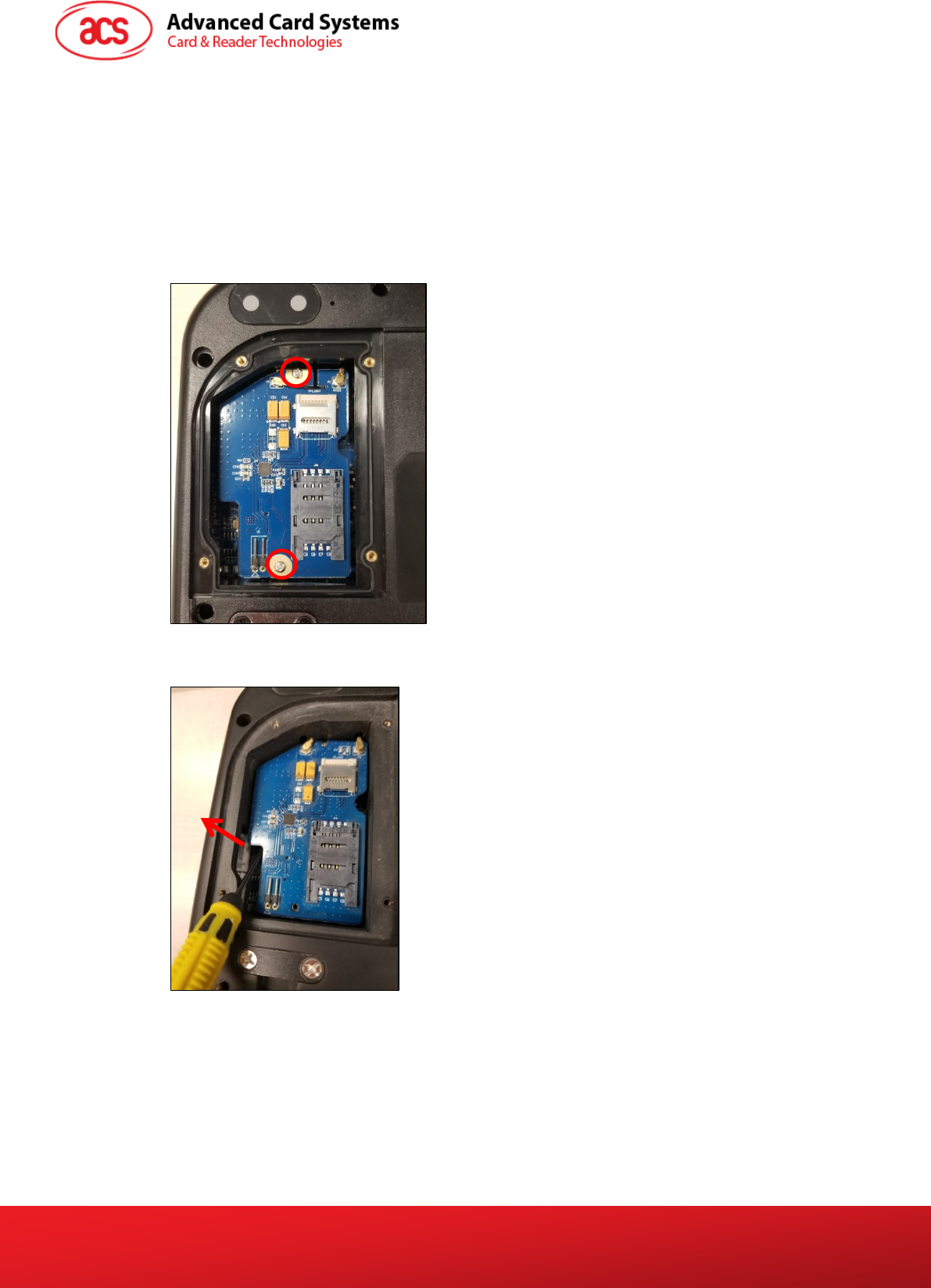
2.6. Replace Real Time Clock Battery
CR2032 coin cell is used for Real Time Clock backup power. The lifetime of the coin cell is around 5
years. If time cannot be stored, it may be caused by low battery.
To replace coin cell:
1. Unscrew two pieces screws and take them out. The exact locations are shown in the image
below.
Note: Be careful in handling the screws so they will not drop inside the bus validator.
2. Using a screw driver, take out the LTE board.
Limited
ACR330 User Manual info@acs.com.hk
Version 1.00 www.acs.com.hk
Page 10 of 16
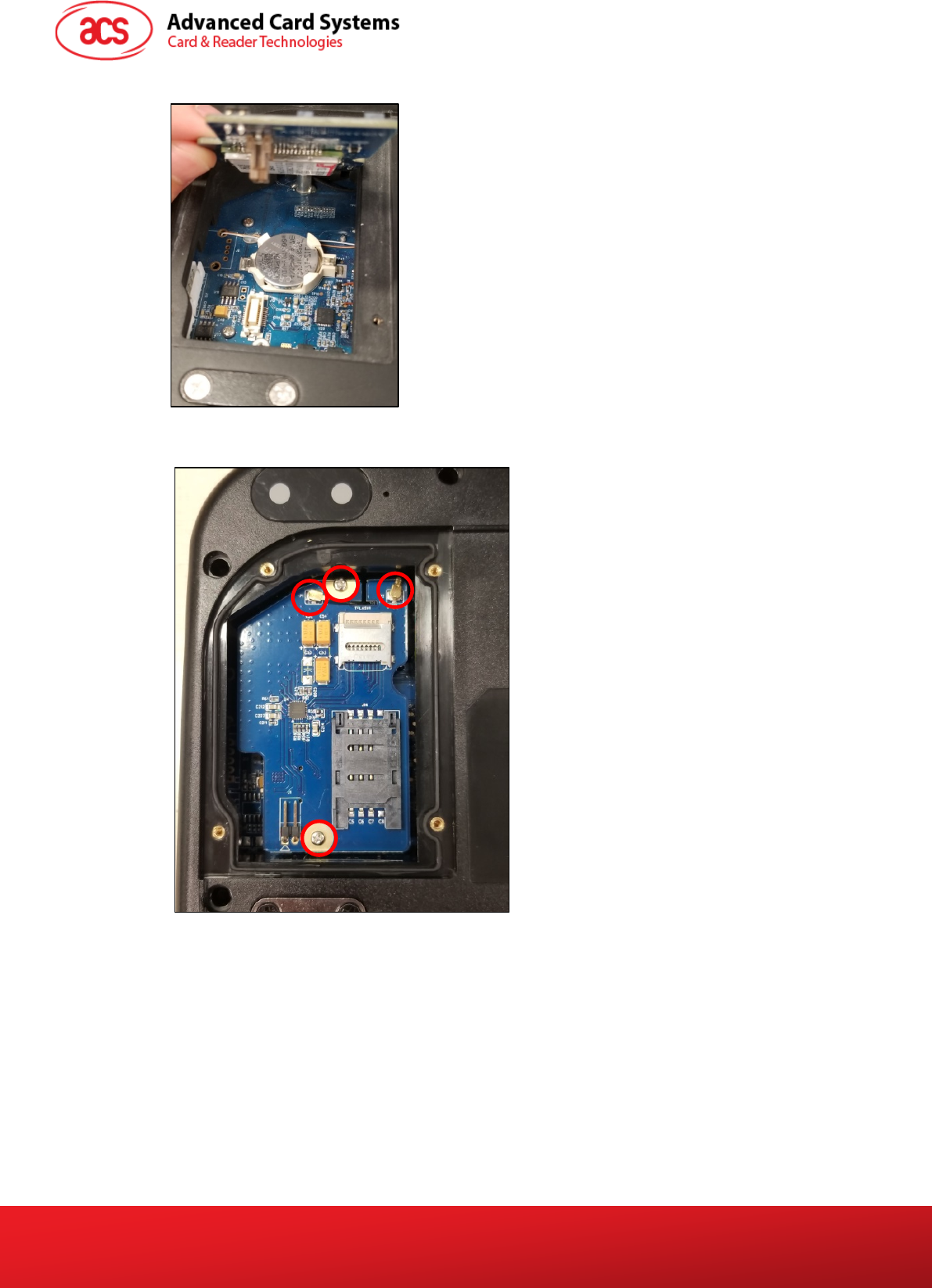
3. The coin cell may now be accessed. Replace the old coin cell with a new one.
4. Return the LTE board. Ensure that the two screws and IPEX connectors are located correctly.
The exact locations are shown in the image below.
Limited
ACR330 User Manual info@acs.com.hk
Version 1.00 www.acs.com.hk
Page 11 of 16
3.0. ACR330 Device Setup
The following sections detail the procedure in setting up the firmware and application to the ACR330.
3.1. Turn device on/off
To turn device on/off, press power button.
To hard power off the device, press and hold power button for around 8 seconds.
The location of the power button is shown in the image below.
3.2. Upgrade the firmware
It is important to upgrade the firmware of the ACR330 first before loading the library and the
application into the device. Below are the components needed and instructions for firmware upgrade.
Some reminders need to be taken note off as well.
Notes:
1. Only use firmware files officially provided by Advanced Card Systems Ltd.
2. Do NOT load the ACR330 firmware file into other ACS readers.
Failure to follow the above reminders may cause damage to the smart card reader.
Components needed:
• ACR330
• SD cards (4GB or above)
• Desktop PC (Windows 7 or above)
• Win32 Disk Imager application
Limited
ACR330 User Manual info@acs.com.hk
Version 1.00 www.acs.com.hk
Page 12 of 16
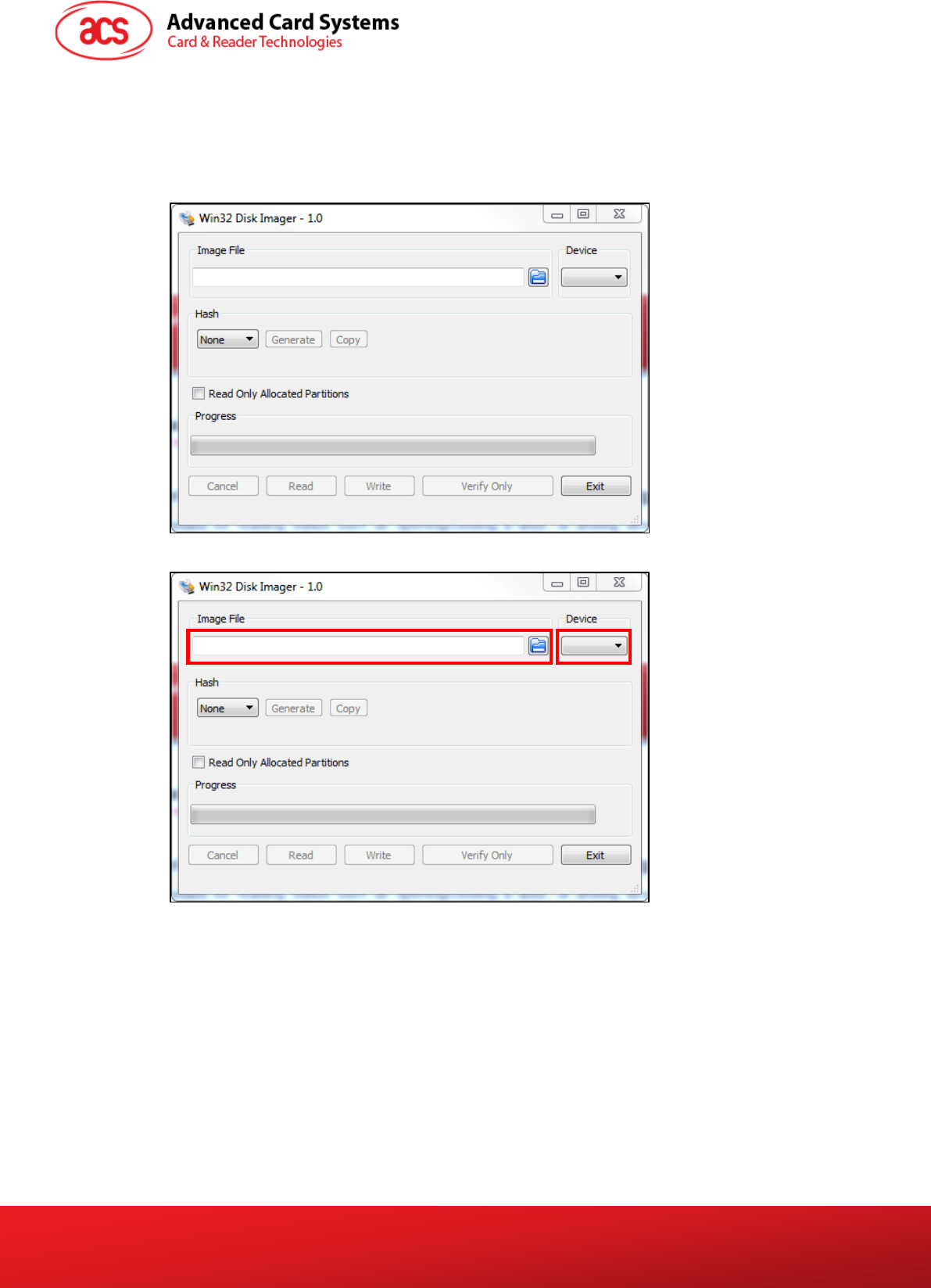
To upgrade the firmware of the ACR330:
1. Plug in an SD card (4GB or above) to the PC.
2. Open Win32 Disk Imager application.
Note: The Win32 Disk Imager application may be downloaded online for free.
3. Select the image file and device.
4. Click Write and wait for the progress bar to be complete.
Limited
ACR330 User Manual info@acs.com.hk
Version 1.00 www.acs.com.hk
Page 13 of 16
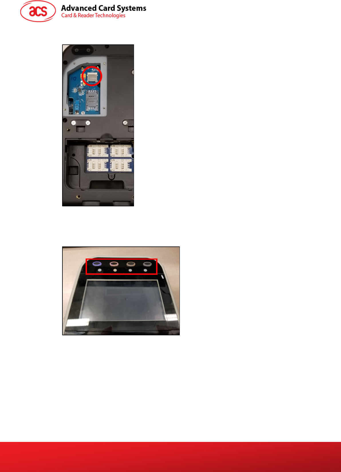
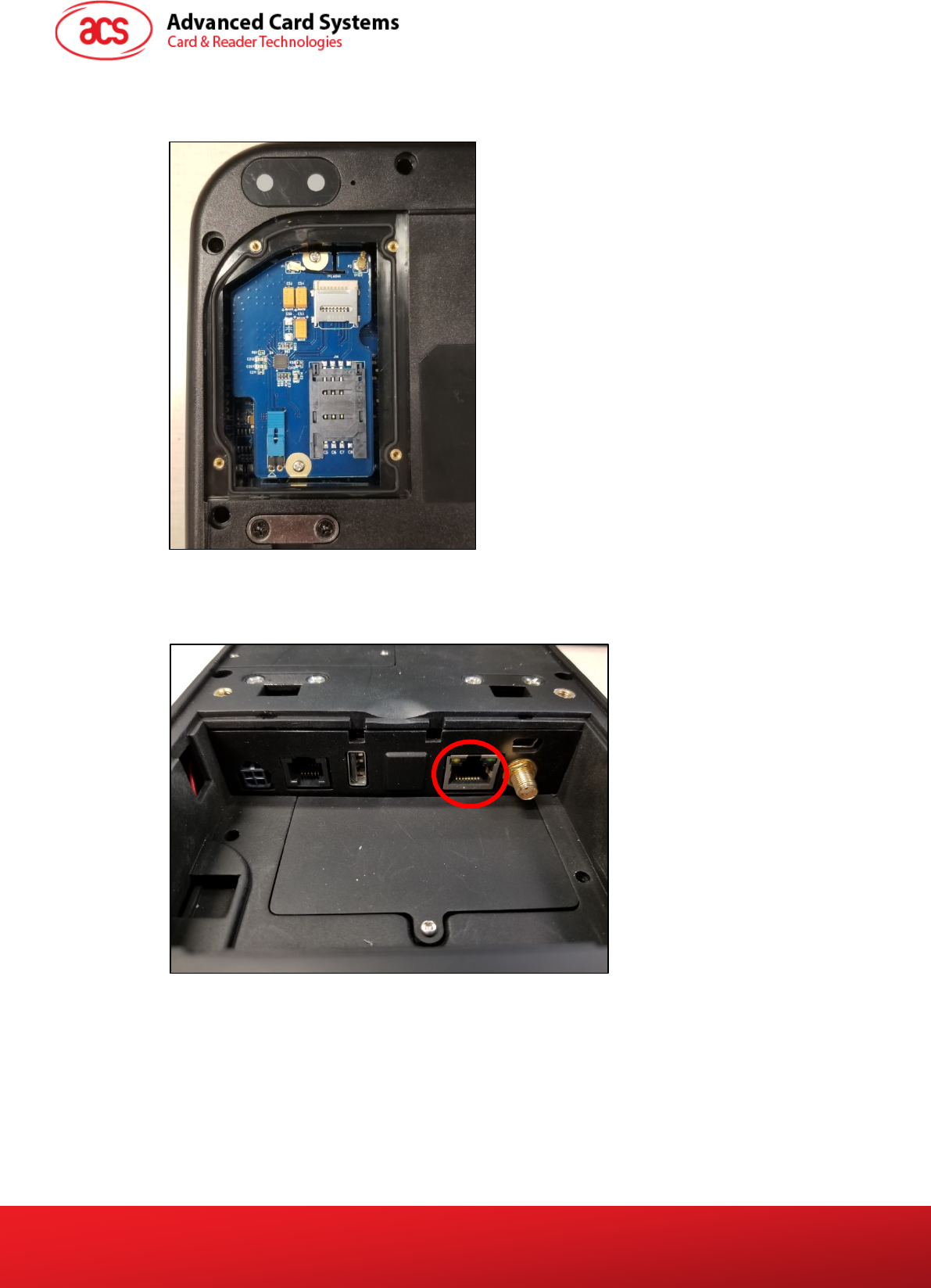
5. Plug in the SD card into the LTE board of the ACR330. The exact location is shown in the
image below.
6. Turn on the ACR330 by plugging in the power cable.
Note: If the LCD does not turn on, press the power button on the top right corner of the
bottom casing.
7. The ACR330 will be upgraded automatically. The LED will keep blinking.
8. After around 8 minutes, the LED will turn off. The upgrade is completed.
9. Remove the SD card.
10. Reboot the device for the changes to take effect.
Limited
ACR330 User Manual info@acs.com.hk
Version 1.00 www.acs.com.hk
Page 14 of 16
3.3. Access ACR330 through PC using LAN
You may access ACR330 through the PC to enable functions which may be needed for operations
(e.g. file transfer). Below are the components needed and instructions for accessing ACR330 through
PC.
Components needed:
• Jumper (to enable the console mode)
Note: Jumper is not included in standard product.
• RS232 debug console cable
• Bitvise SSH Client (Tunnelier) SFTP Application
• Note: The Bitvise SSH Client (Tunnelier) SFTP Software may be downloaded from
https://www.bitvise.com/ssh-client-download.
• LAN cable
Limited
ACR330 User Manual info@acs.com.hk
Version 1.00 www.acs.com.hk
Page 15 of 16
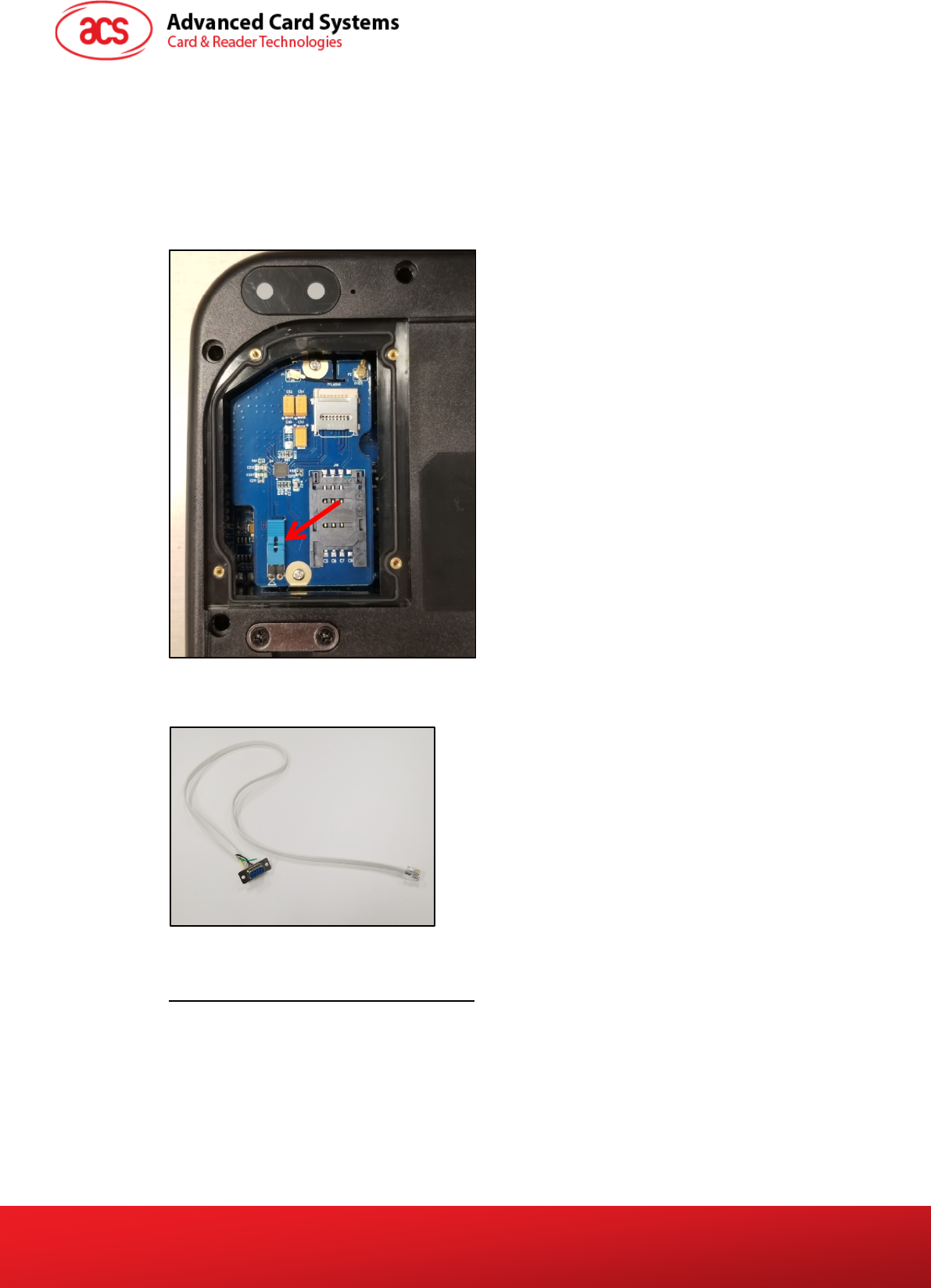
To access ACR330 using LAN:
1. On the LTE board, plug in jumper to enable console mode.
Note: Jumper is not included in standard product.
2. Connect ACR330 to the Ethernet using a LAN cable. The exact location of the Ethernet port
at the back of the ACR330 is shown in the image below.
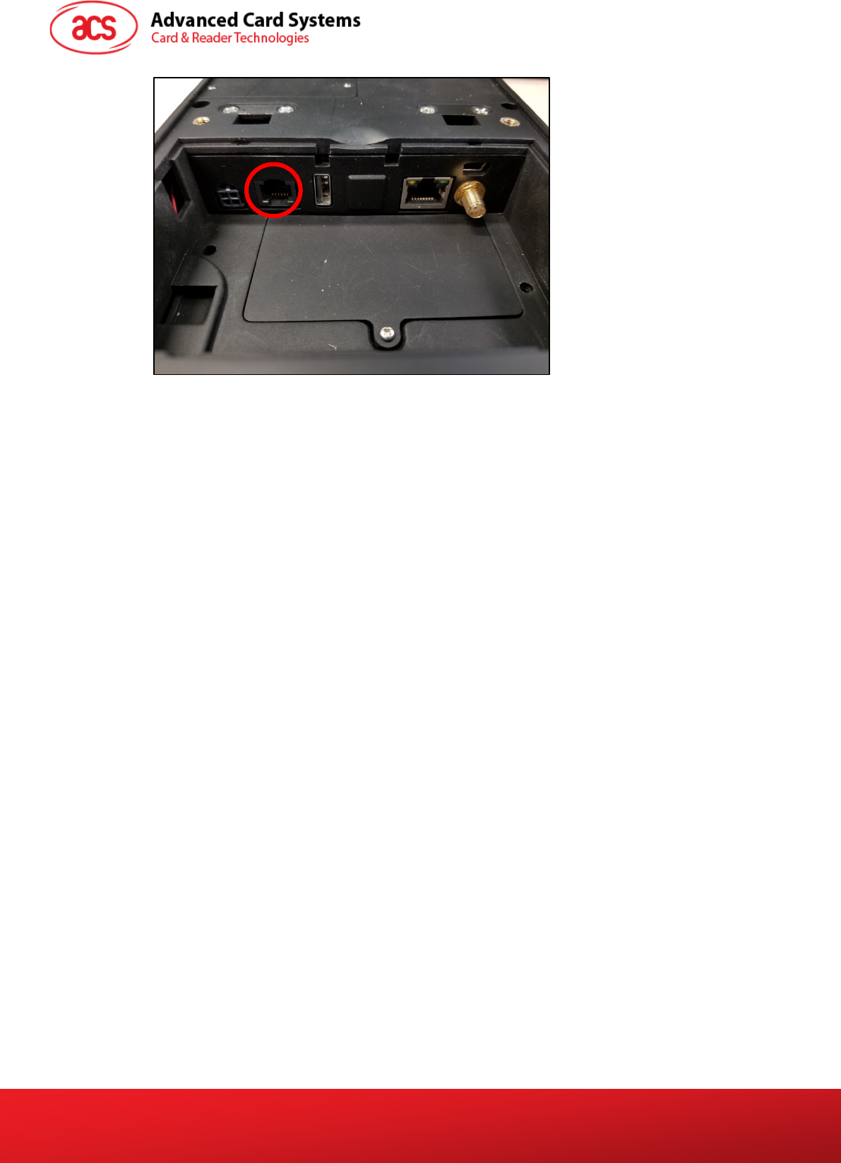
3. Connect ACR330 to the PC using the RS232 debug console cable. The exact location of the
RJ11 serial port at the back of the ACR330 is shown in the image below.
Note: Connect the other end of the cable to the PC serial port or USB-RS232 converter.
Limited
ACR330 User Manual info@acs.com.hk
Version 1.00 www.acs.com.hk
Page 16 of 16
4. Turn on the ACR330.
5. Login in to the console.
a. Login name: root
b. Password: root
Note: If [root@Linux/root] # is shown, it means login is successful
6. Type “ifconfig eth0” to get IP address.
7. Open the Bitvise SSH Client (Tunnelier) SFTP Application on the PC.
8. Login with the IP address in step 5.
a. Login name: machinekit
b. Password: machinekit
9. The ACR330 may now be accessed on the PC.
Note: For more details, please refer to ACR330 API.chm.
Limited

FCCCaution.
Thisdevicecomplieswithpart15oftheFCCRules.Operationissubjecttothefollowingtwo
conditions:(1)Thisdevicemaynotcauseharmfulinterference,and(2)thisdevicemustaccept
anyinterferencereceived,includinginterferencethatmaycauseundesiredoperation.
AnyChangesormodificationsnotexpresslyapprovedbythepartyresponsibleforcompliance
couldvoidtheuser'sauthoritytooperatetheequipment.
Note:ThisequipmenthasbeentestedandfoundtocomplywiththelimitsforaClassBdigital
device,pursuanttopart15oftheFCCRules.Theselimitsaredesignedtoprovidereasonable
protectionagainstharmfulinterferenceinaresidentialinstallation.Thisequipmentgenerates
usesandcanradiateradiofrequencyenergyand,ifnotinstalledandusedinaccordancewiththe
instructions,maycauseharmfulinterferencetoradiocommunications.However,thereisno
guaranteethatinterferencewillnotoccurinaparticularinstallation.Ifthisequipmentdoes
causeharmfulinterferencetoradioortelevisionreception,whichcanbedeterminedbyturning
theequipmentoffandon,theuserisencouragedtotrytocorrecttheinterferencebyoneor
moreofthefollowingmeasures:
‐Reorientorrelocatethereceivingantenna.
‐Increasetheseparationbetweentheequipmentandreceiver.
‐Connecttheequipmentintoanoutletonacircuitdifferentfromthattowhichthereceiveris
connected.
‐Consultthedealeroranexperiencedradio/TVtechnicianforhelp.
FCC Radiation Exposure Statement:
This equipment complies with FCC radiation exposure limits set forth for an
uncontrolled environment .This equipment should be installed and operated with
minimum distance 20cm between the radiator& your body.