Advanced Card Systems AET62 Contactless Smart Card Reader with Fingerprint Scanner User Manual AET62 V1 0
Advanced Card Systems Limited Contactless Smart Card Reader with Fingerprint Scanner AET62 V1 0
Users Manual
Advanced Card Systems Ltd. Website: www.acs.com.hk
Email:
info@acs.com.hk
AET62
User Manual
AET62 Design Specification
Version 1.0 8-DEC-09
Page
2
of
18
AET62
Revision History
Version Date Prepared By Description
1.00 28 Mar 2008 Jason Ngan Initial release
1.10 24 Aug 2009 Jason Ngan Updated Features

AET62 Design Specification
Version 1.0 8-DEC-09
Page
3
of
18
AET62
Table of Contents
1.0.
Introduction ................................................................................................................. 4
2.0.
FEATURES................................................................................................................... 5
3.0.
SYSTEM BLOCK DIAGRAM....................................................................................... 6
4.0.
HARDWARE INTERFACES ........................................................................................ 7
4.1.
Power Supply.........................................................................................................................7
4.2.
USB Interface ........................................................................................................................7
4.2.1.
Endpoints ......................................................................................................................7
4.3.
Bi-Color LED ..........................................................................................................................8
4.4.
Buzzer (optional)....................................................................................................................8
4.5.
SAM Interface (optional) ........................................................................................................8
4.6.
Built-in Antenna .....................................................................................................................8
4.7.
FINGERPRINT SCANNNER .................................................................................................8
5.0.
Commands for Contact and Contactless Interfaces Handling............................ 10
5.1.
PSEUDO APDUS IN CONTACTLESS READER................................................................11
5.1.1.
Direct Transmit............................................................................................................11
6.0.
APIs for Fingerprint Sensor..................................................................................... 12
6.1.
PTOpen................................................................................................................................12
6.2.
PTClsoe ...............................................................................................................................12
6.3.
PTGrab ................................................................................................................................13
6.4.
Get Response......................................................................................................................14
6.5.
Bi-Color LED and Buzzer Control ........................................................................................15
6.6.
Get the Firmware Version of the reader ..............................................................................17
7.0.
Technical Specification............................................................................................ 18

AET62 Design Specification
Version 1.0 8-DEC-09
Page
4
of
18
AET62
1.0. Introduction
AET62 is a USB 2.0 full speed Contactless card reader, which is the interface for the communication
between a computer and a smart card reader. Simultaneously, it is also a fingerprint reader using strip
sensor.

AET62 Design Specification
Version 1.0 8-DEC-09
Page
5
of
18
AET62
2.0. FEATURES
Slope casing for strip sensor for easy finger snapping - as small as possible
Horizontal card placement
The card should not cover the strip sensor.
Add weight to prevent swinging
Un-detachable USB wire of length same as ACR122
USB version 1.1 full speed
A bi-colour LED shows the statues of device power supply and smart card reader
ISO14443 Parts 1-4 Type A & B, Mifare, Desfire, Topaz, ISO/IEC18092 (NFC) compliant – all
3 modes
Maxmium smart card operation speed: 424 kbps
CCID standard,
PC/SC compliant
Support anti-collision. Even in the presence of multiple cards, at least 1 tag can be correctly
identified.
(By PC/SC Escape Commands) Allow manual card polling option
Operating Distance for different Tags ~ 40mm
Optional: 1 SAM slot (Not changing often)
Match-on-device
BioAPI 1.1, Windows Biometric Framework (WBF)
CE & FCC, RoHS compliant, REACH compliant
(Optional) VCCI
OS supported: Windows 2000, 2003, XP 32, XP 64, Vista 32 and Vista 64, Linux, Mac
AET62 Design Specification
Version 1.0 8-DEC-09
Page
6
of
18
AET62
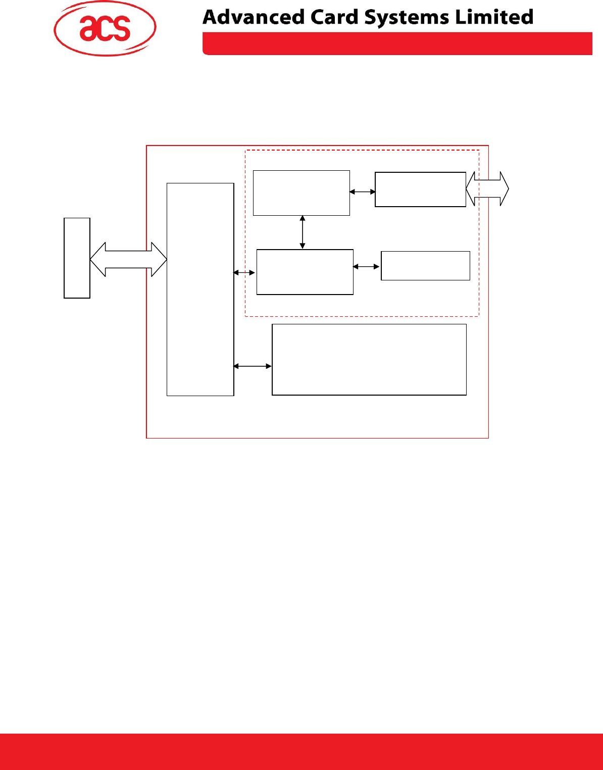
3.0. SYSTEM BLOCK DIAGRAM
AET62 is a merge version with ACR122 and finger print sensor. ACR122 is a contactless reader. The
system block of AET62 is shown as follow:
The USB Hub Controller is the communication interface between the PC and the host controller and
fingerprint sensor via USB port connection. The companion chip get the fingerprint image form the
Strip sensor and contains the fingerprint template extraction and matching algorithms. The template
matching can be performed in device. The AET62 is powered from USB port without external power
supply.
NFC Card
USB
Hub
Controller
PN532
NFC Interface Chip
Computer
AET62
SAM slot
USB
Interface
Companion Chip and Fingerprint Sensor
(Strip Sensor)
Built-In Antenna
Host controller
ACR122
Contactless Interface
Carrier = 13.56MHz
AET62 Design Specification
Version 1.0 8-DEC-09
Page
7
of
18
AET62
4.0. HARDWARE INTERFACES
4.1. Power Supply
The AET62 requires a voltage of 5V DC, 150mA regulated power supply, and gets the power supply
from PC.
4.2. USB Interface
The AET62 is connected to a computer through USB as specified in the USB Specification 1.1. The
AET62 is working in Full speed mode, i.e. 12 Mbps.
4.2.1. Endpoints
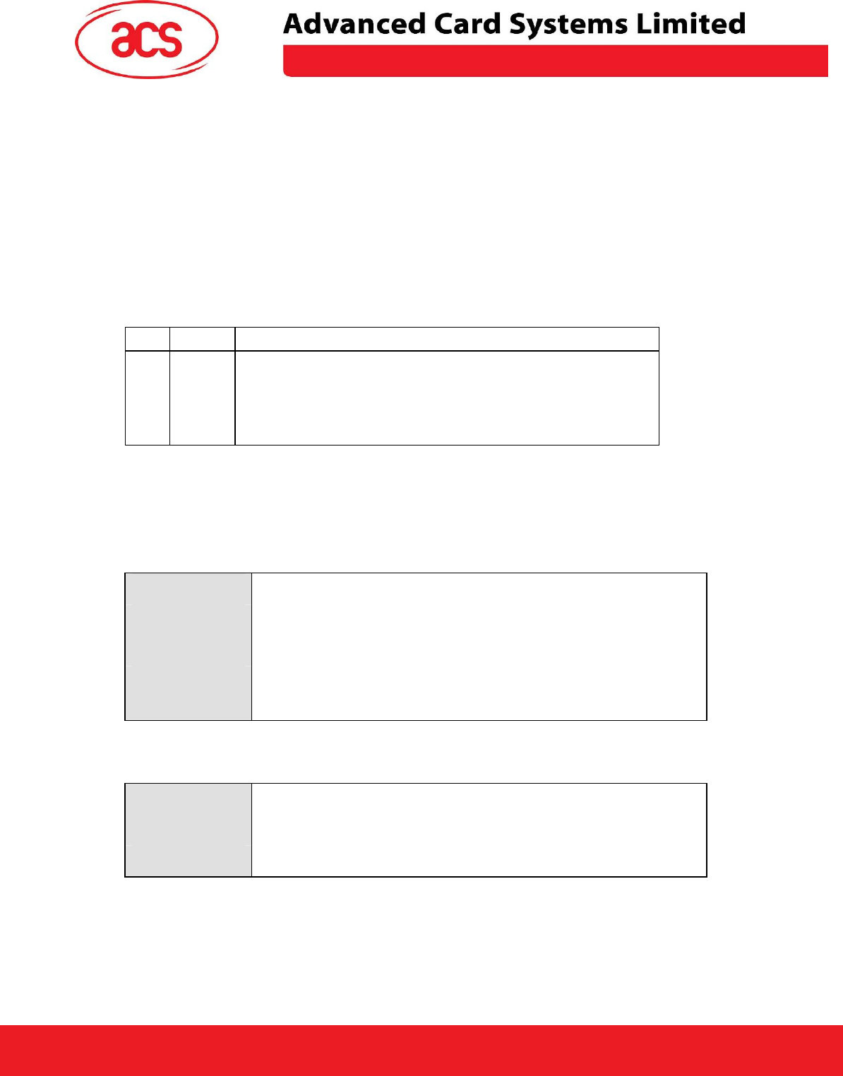
The AET62 uses the following endpoints to communicate with the host computer:
4.2.1.1. Smart Card Reader
Control Endpoint For setup and control purpose
Bulk OUT For command to sent from host to AET62 (data packet size is 64 bytes)
Bulk IN For response to sent from AET62 to host (data packet size is 64 bytes)
Interrupt IN For card status message to sent from AET62 to host (data packet size is 8
bytes)
4.2.1.2. Finger Print Device
Control Endpoint For setup and control purpose
Bulk OUT For command to sent from host to Device (data packet size is 64 bytes)
Bulk IN For response to sent from Device to host (data packet size is 64 bytes)
Pin Signal Function
1 V
BUS
+5V power supply for the reader (Max 200mA, Normal 100mA)
2 D- Differential signal transmits data between AET62 and PC.
3 D+ Differential signal transmits data between AET62 and PC.
4 GND Reference voltage level for power supply

AET62 Design Specification
Version 1.0 8-DEC-09
Page
8
of
18
AET62
4.3. Bi-Color LED
• User-controllable Bi-color LED. Red and Green Color.
• The Green Color LED will be blinking if the “Card Interface” is not connected.
• The Green Color LED will be turned on if the “Card Interface” is connected.
• The Green Color LED will be flashing if the “Card Interface” is operating.
• The Red Color LED is controlled by the application only.
4.4. Buzzer (optional)
• User-controllable buzzer.
• The default Buzzer State is OFF
4.5. SAM Interface (optional)
• One SAM socket is provided.
4.6. Built-in Antenna
• 6 turns symmetric loop antenna. Center tapped.
• The estimated size = 50mm x 40mm.
• The loop inductance should be around ~ 1.6uH to 2.5uH
• Operating Distance for different Tags ~ 40mm to 50mm
• No anti-collision. Only one Tag can be accessed at any one time.
• Contactless Interface Carrier = 13.56MHz
4.7. FINGERPRINT SCANNNER
AET62 is built around the companion chip and fingerprint sensor.
Fingerprint sensor active capacitive sensing provides a much higher immunity to parasitic effects
leading to a higher signal-to-noise ratio and the ability to capture a wider range of fingerprints
than competing technologies, such as passive capacitive sensing. The matching algorithm will be
stored in the Companion chip. The fingerprint matching will be performed on the device. It can
provides “Match on device” feature.
Typically there are two processes involved in a biometric application:
Enrollment:
Before the identity of an individual can be verified via his/her fingerprints, it is necessary to
capture one or several fingerprint samples. This process is called enrollment. The samples

AET62 Design Specification
Version 1.0 8-DEC-09
Page
9
of
18
AET62
are referred to as fingerprint templates and can be stored on a broad range of media such as
computer storage devices or smartcards.
Verification:
The verification process requires a user to verify his identity by placing his finger on the
fingerprint scanner sensor. The live fingerprint is compared with a stored template using a
matching algorithm in order to determine whether they represent the same set of fingerprint.
The matching result is then made available to the computer.
When using the fingerprint device, the security level is mainly governed by two parameters:
False Acceptance Rate (FAR):
FAR is the probability that a false sample matches with the original template previously
extracted from the subject’s fingerprint images during enrollment.
False Rejection Rate (FRR):
FRR is the rate at which the system incorrectly rejects a legitimate attempt to verify.
AET62 Design Specification
Version 1.0 8-DEC-09
Page
10
of
18
AET62
5.0. Commands for Contact and Contactless Interfaces
Handling
The contactless interface is operating on the top of contact interface. Some Pseudo APDUs are
defined for contactless interface. If the reader finds that the APDUs are for contactless interface, the
APDUs will be routed to the contactless interface, otherwise, the APDUs will be routed to contact
interface. The Contact and Contactless Interfaces are able to be operating at the same time.
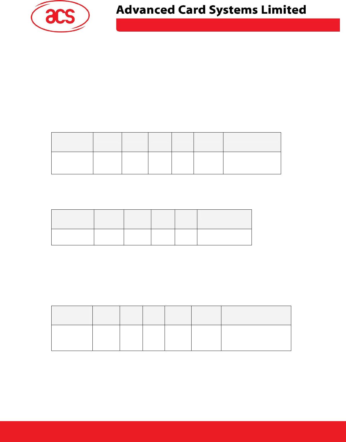
• The Pseudo APDU “Direct Transmit” is used for sending commands to the
contactless interface
Command
Class INS P1 P2 Lc Data In
Direct
Transmit
0xFF 0x00 0x00 0x00 Number
of Bytes
to send
PN532_Contactless
Command
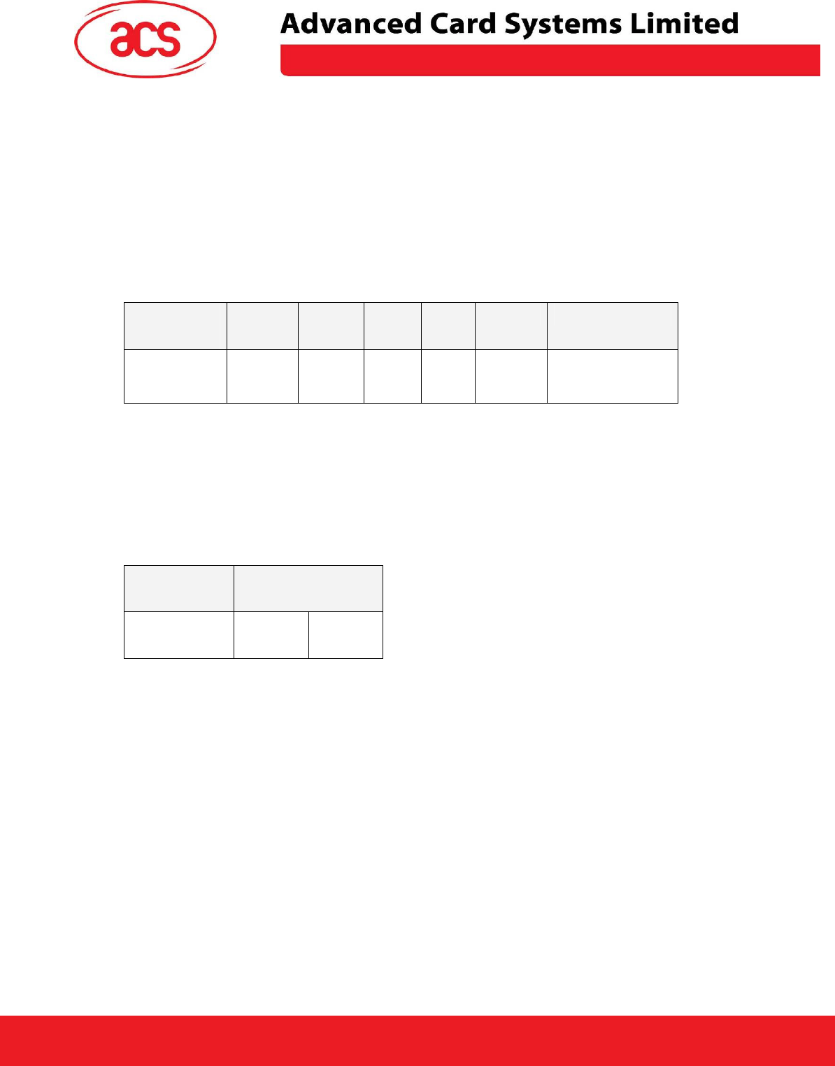
2. The Pseudo APDU “Get Response” is used for retrieving the responses from the contactless
interface.
Command
Class INS P1 P2 Le
Get Response 0xFF 0xC0 0x00 0x00 Number of Bytes to
retrieve
If the reader finds that the APDU is in the form of “FF 00 00 00 Lc XX XX ..” or “FF C0 00 00 Le”, the
APDU will be routed to the contactless interface.
Also, one Pseudo APDU “Bi-Color LED and Buzzer Control” is defined for controlling the LED and
Buzzer.
Command
Class INS P1 P2 Lc Data In
(4 Bytes)
Bi-Color and
Buzzer
LED Control
0xFF 0x00 0x40 LED
State
Control
0x04 Blinking Duration Control
Similarly, if the reader finds that the APDU is in the form of “FF 00 40 XX 04 XX XX XX XX”, the
APDU will be used for setting the LED and Buzzer State.
The contact interface must be activated in order to send commands to the contactless or LED
interface.
AET62 Design Specification
Version 1.0 8-DEC-09
Page
11
of
18
AET62
5.1. PSEUDO APDUS IN CONTACTLESS READER
PCSC interface is used for exchanging APDUs and Responses between the PC and Tag. The AET62
will handle the required protocol internally. AET62 comes with two primitive commands for this
purpose.
5.1.1. Direct Transmit
To send an APDU (PN532 and Contactless Commands), and the length of the Response Data will be
returned.
Table 1.0A: Direct Transmit Command Format (Length of the PN532_Contactless Command + 5
Bytes)
Command
Class INS P1 P2 Lc Data In
Direct
Transmit
0xFF 0x00 0x00 0x00 Number
of Bytes
to send
PN532_Contactless
Command
Lc: Number of Bytes to Send (1 Byte)
Maximum 255 bytes
Data In: PN532_Contactless Command
The data to be sent to the PN532 and Contactless Tag.
Table 1.0B: Direct Transmit Response Format (2 Bytes)
Response
Data Out
Result
SW1 SW2
Data Out: SW1 SW2
Status Code returned by the reader.

AET62 Design Specification
Version 1.0 8-DEC-09
Page
12
of
18
AET62
6.0. APIs for Fingerprint Sensor
6.1. PTOpen
PT_STATUS PTOpen(
IN PT_CHAR *pszDsn
OUT PT_CONNECTION *phConnection
)
Description:
Open a new fingerprint module connection
Parameters :
pszDsn :
ASCII string describing the FM connection parameters. Examples: “USB”
phConnection:
Connection handle result.
Return value:
PT_STATUS:
Return value.
6.2. PTClsoe
PT_STATUS PTClose(
IN PT_CONNECTION hConnection
)
Description:
Close a fingerprint module connection
Parameters :
hConnection:
Connection handle to be closed.
Return value:
PT_STATUS:
Return value.

AET62 Design Specification
Version 1.0 8-DEC-09
Page
13
of
18
AET62
6.3. PTGrab
PT_STATUS PTGrab(
IN PT_CONNECTION hConnection
IN PT_BYTE byType
IN PT_LONG lTimeout
IN PT_BOOL boWaitForAcceptableFinger
OUT PT_DATA **ppGrabbedData
IN PT_DATA *pSignData
OUT PT_DATA **ppSignature
)
Description:
Scan the finger and return the scanned finger image
hConnection:
FM Handle
byType:
The returned data type
lTimeout:
Timeout value in milliseconds.
boWaitForAcceptableFinger:
Value: Description
True Return the finger image if the finger quality would be acceptable
False Always returns the finger image after a single swipe
ppGrabbedData:
Address of the data pointer,
pSignData:
Reserved, Null value
ppSignature:
Reserved, Null value
For the detail, please you can refer UPEK ESS&TFM Application Communication Layer document.
AET62 Design Specification
Version 1.0 8-DEC-09
Page
14
of
18
AET62
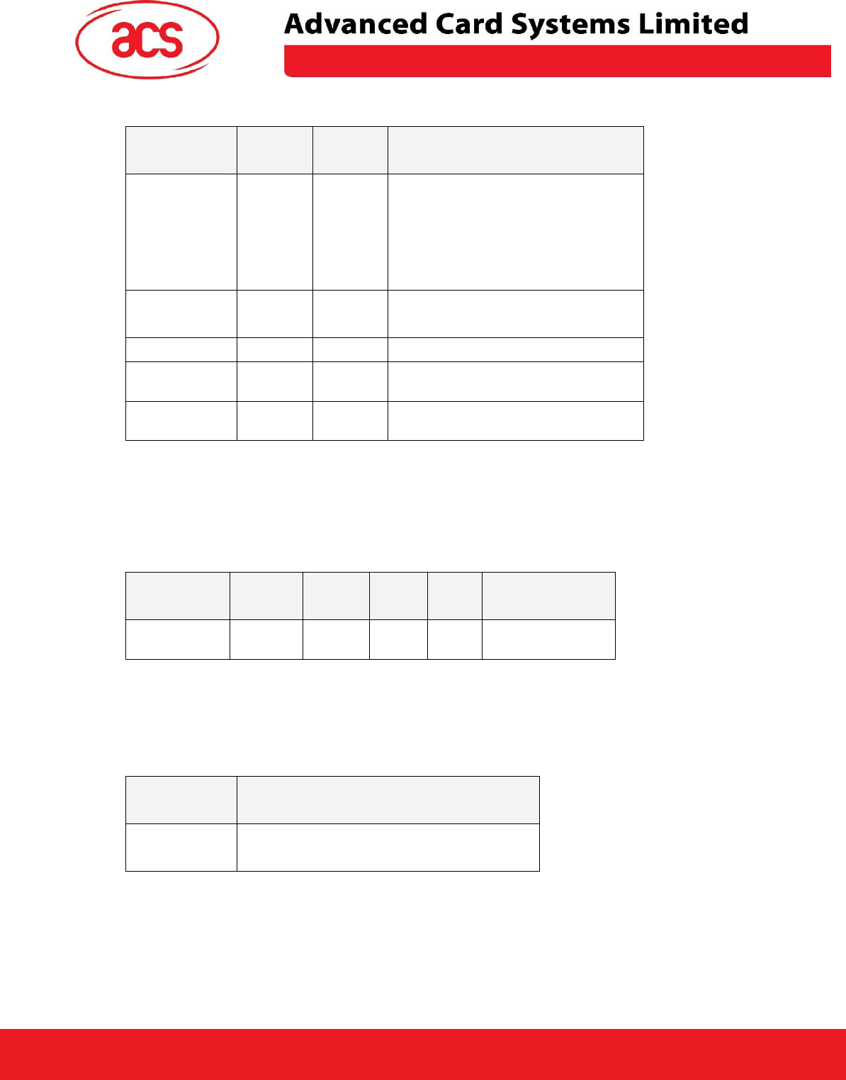
Table 1.0C: Status Code
Results
SW1 SW2 Meaning
Success 61 LEN The operation is completed successfully.
The response data has a length of LEN
bytes.
The APDU “Get Response” should be
used to retrieve the response data.
Error
63 00 The operation is failed.
Time Out Error 63 01 The PN532 does not response.
Checksum Error
63 27 The checksum of the Contactless
Response is wrong.
Parameter Error 63 7F The PN532_Contactless Command is
wrong.
6.4. Get Response
To retrieve the response data after the “Direct Command” is issued.
Table 2.0A: Get Response Command Format (5 Bytes)
Command
Class INS P1 P2 Le
Get Response 0xFF 0xC0 0x00 0x00 Number of Bytes to
retrieve
Le: Number of Bytes to Retrieve (1 Byte)
Maximum 255 bytes
Table 2.0B: Get Response Format (Le bytes, Length of the Response Data)
Response
Data Out
Result
Response Data
Data Out: Response Data, or Error Code “63 00” will be given if no response data is available.

AET62 Design Specification
Version 1.0 8-DEC-09
Page
15
of
18
AET62
Remark:
In general, the Pseudo APDUs “Direct Transmit” and “Get Response” are used in pairs. Once the
APDU “Direct Transmit” is sent, the reader will return the length of the response data. Then, the
APDU “Get Response” is immediately used to retrieve the actual response data.
6.5. Bi-Color LED and Buzzer Control
This APDU is used to control the states of the Bi-Color LED and Buzzer.
Table 3.0A: Bi-Color LED and Buzzer Control Command Format (9 Bytes)
Command
Class INS P1 P2 Lc Data In
(4 Bytes)
Bi-Color and
Buzzer
LED Control
0xFF 0x00 0x40 LED
State
Control
0x04 Blinking Duration Control
P2: LED State Control
Table 3.0B: Bi-Color LED and Buzzer Control Format (1 Byte)
CMD Item Description
Bit 0 Final Red LED State 1 = On; 0 = Off
Bit 1 Final Green LED State 1 = On; 0 = Off
Bit 2 Red LED State Mask 1 = Update the State
0 = No change
Bit 3 Green LED State Mask 1 = Update the State
0 = No change
Bit 4 Initial Red LED Blinking State 1 = On; 0 = Off
Bit 5 Initial Green LED Blinking State 1 = On; 0 = Off
Bit 6 Red LED Blinking Mask 1 = Blink
0 = Not Blink
Bit 7 Green LED Blinking Mask 1 = Blink
0 = Not Blink
AET62 Design Specification
Version 1.0 8-DEC-09
Page
16
of
18
AET62
Data In: Blinking Duration Control
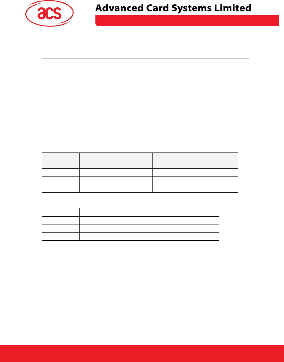
Table 3.0C: Bi-Color LED Blinking Duration Control Format (4 Bytes)
Byte 0 Byte 1 Byte 2 Byte 3
T1 Duration
Initial Blinking State
(Unit = 100ms)
T2 Duration
Toggle Blinking State
(Unit = 100ms)
Number of
repetition
Link to Buzzer
Byte 3: Link to Buzzer. Control the buzzer state during the LED Blinking.
0x00: The buzzer will not turn on
0x01: The buzzer will turn on during the T1 Duration
0x02: The buzzer will turn on during the T2 Duration
0x03: The buzzer will turn on during the T1 and T2 Duration.
Data Out: SW1 SW2. Status Code returned by the reader.
Table 3.0D: Status Code
Results
SW1 SW2 Meaning
Success 90 Current LED State The operation is completed successfully.
Error
63 00 The operation is failed.
Table 3.0E: Current LED State (1 Byte)
Status Item Description
Bit 0 Current Red LED 1 = On; 0 = Off
Bit 1 Current Green LED 1 = On; 0 = Off
Bits 2 – 7 Reserved
Remark:
1. The LED State operation will be performed after the LED Blinking operation is completed.
2. The LED will not be changed if the corresponding LED Mask is not enabled.
3. The LED will not be blinking if the corresponding LED Blinking Mask is not enabled. Also, the
number of repetition must be greater than zero.
4. T1 and T2 duration parameters are used for controlling the duty cycle of LED blinking and Buzzer
Turn-On duration. For example, if T1=1 and T2=1, the duty cycle = 50%. #Duty Cycle = T1 / (T1 +
T2).
5. To control the buzzer only, just set the P2 “LED State Control” to zero.
6. The make the buzzer operating, the “number of repetition” must greater than zero.
7. To control the LED only, just set the parameter “Link to Buzzer” to zero.
AET62 Design Specification
Version 1.0 8-DEC-09
Page
17
of
18
AET62
6.6. Get the Firmware Version of the reader
To retrieve the firmware version of the reader.
Table 4.0A: Get Firmware Version Command Format (5 Bytes)
Command
Class INS P1 P2 Le
Get Response 0xFF 0x00 0x48 0x00 0x00
Table 4.0B: Get Firmware Version Response Format (10 bytes)
Response
Data Out
Result
Firmware Version
E.g. Response = 41 43 52 31 32 32 55 31 30 31 (Hex) = ACR122U101 (ASCII)
AET62 Design Specification
Version 1.0 8-DEC-09
Page
18
of
18
AET62
7.0. Technical Specification
Universal Serial Bus Interface
Power source ....................................... From USB
Speed................................................... 12 Mbps (Full Speed)
Supply Voltage ..................................... Regulated 5V DC
Supply Current ..................................... 300mA (maximum); 100mA (standby); 150mA (normal)
Contactless Smart Card Interface
Standard............................................... MIFARE Classic, ISO14443-4 Type A & B, FeliCa, ISO/IEC 18092 NFC
Operating Frequency ............................ 13.56 MHz
Smart card read / write speed............... 106, 212, 424 kbps
SAM Interface (optional SAM Socket)
Standard............................................... ISO 7816
Protocol................................................ T=0 protocol
Operating Frequency............................ 4 MHz
Smart card read / write speed............... 9600 - 115200 bps
Fingerprint Sensor Interface
Sensor Type ......................................... Swipe
Image resolution................................... 508 DPI
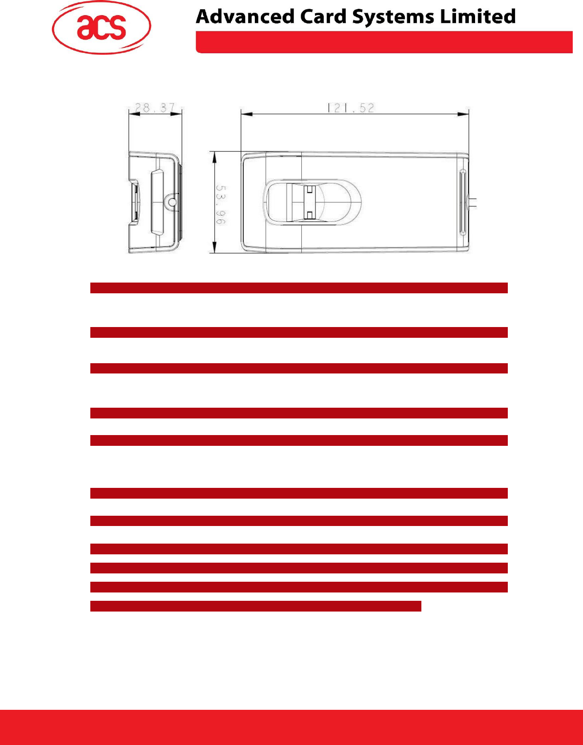
Case
Dimensions........................................... 98 mm (L) x 65 mm (W) x 12.8 mm (H)
Material ................................................ Polycarbonate (PC)
Color..................................................... Pearl White
Antenna Size ........................................ 50mm x 40mm
Operating distance ............................... up to 30 mm (depended on tag type)
Built-in peripherals
Bi-Color LED ........................................ Bi-Color LED, Red and Green
Buzzer .................................................. Monotone (optional)
Operating Conditions
Temperature......................................... 0 - 50° C
Humidity ............................................... 10% - 80%
Cable Connector
Length .................................................. 1.5 M (USB)
Standard/Certifications
CE, FCC
OS
Windows 2K, XP, Vista
OEM
OEM-Logo possible, customer-specific colors, casing, and card connector
Warning:
This device complies with part 15 of the FCC Rules. Operation is subject to the following two conditions:
(1) This device may not cause harmful interference, and (2) this device must accept any interference received,
including interference that may cause undesired operation.
Changes or modifications not expressly approved by the party responsible for compliance could void the
user's authority to operate the equipment.