Advanced RF Technologies ADRF25K Dual Band (PCS & Cellular) bi-directional amplifier User Manual Manual
Advanced RF Technologies, Inc. Dual Band (PCS & Cellular) bi-directional amplifier Manual
UserManual.wiki
>
Advanced RF Technologies
>
ADRF25K User Manual
Manual
Navigation menu
Upload a User Manual
Namespaces
Wiki Guide
HTML
PDF
Info
Views
User Manual
Discussion / Help
Navigation
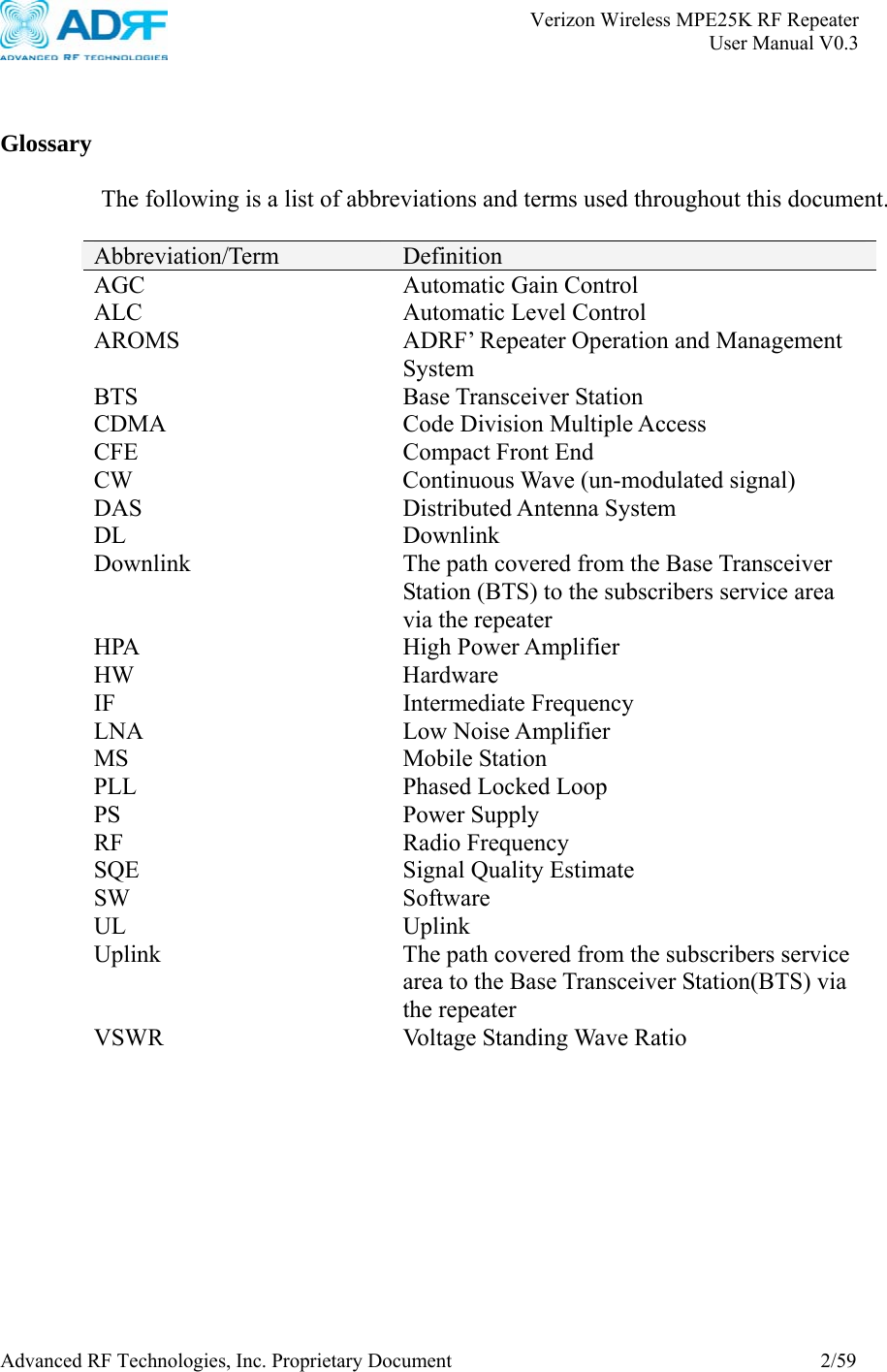
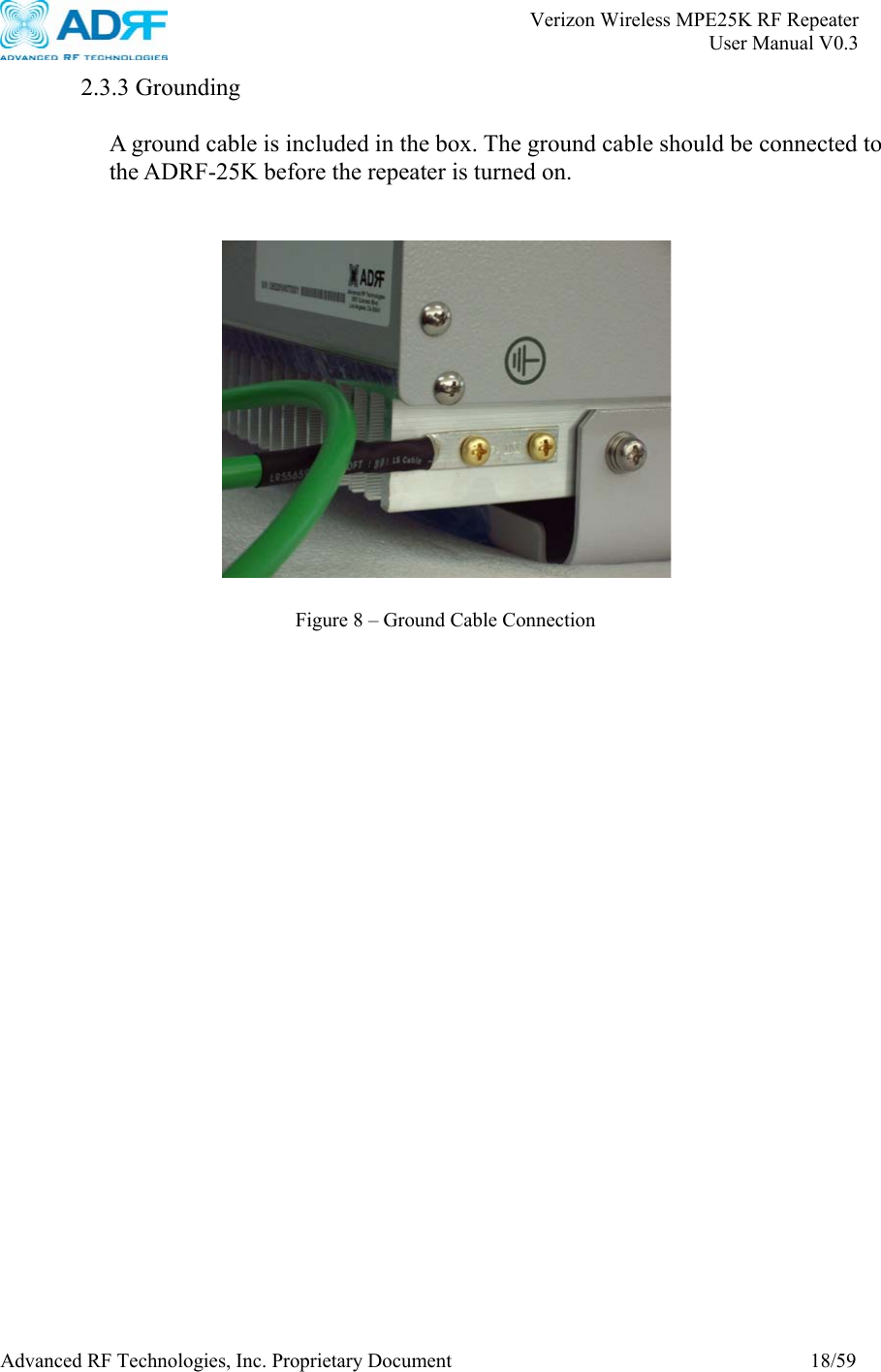
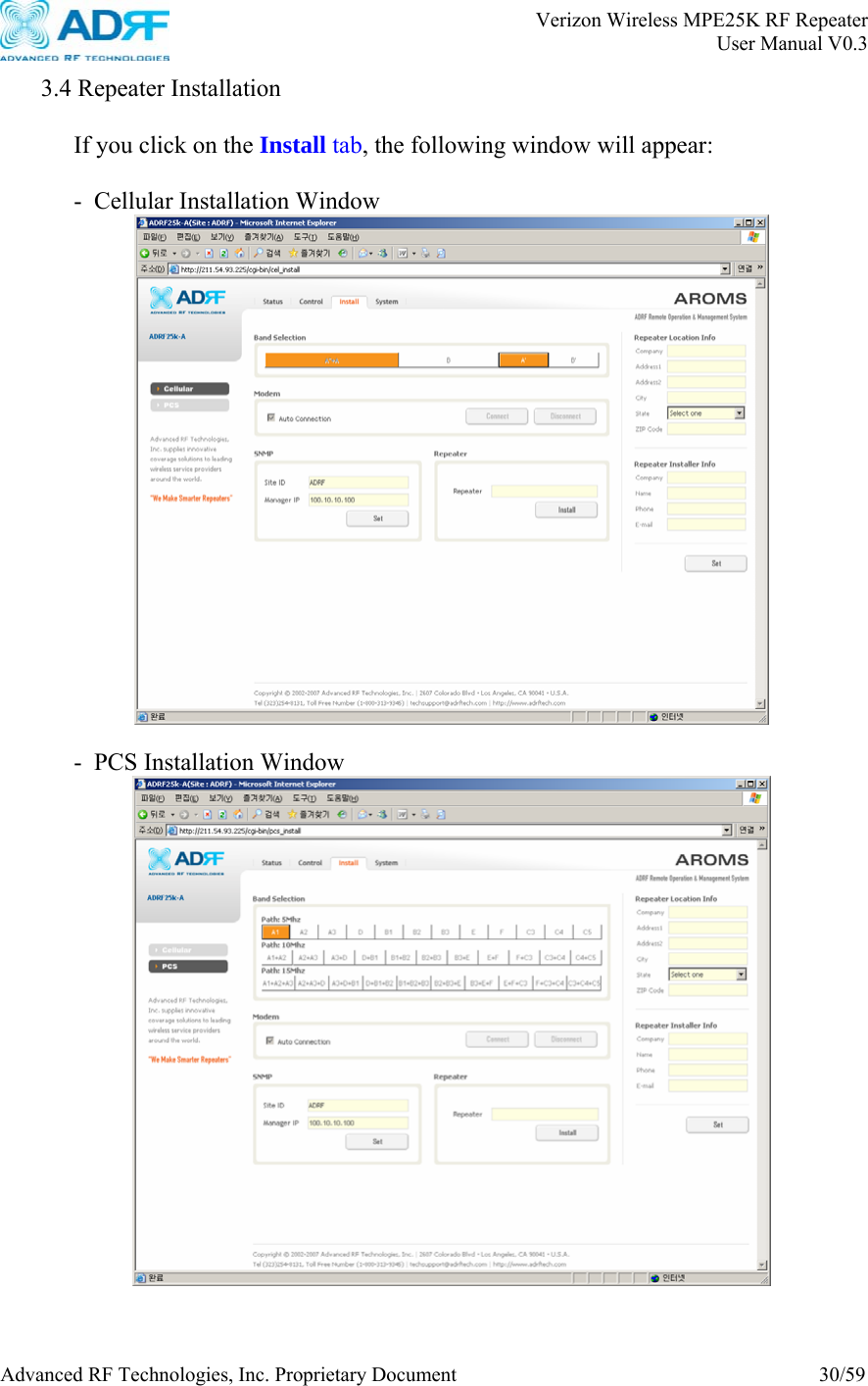
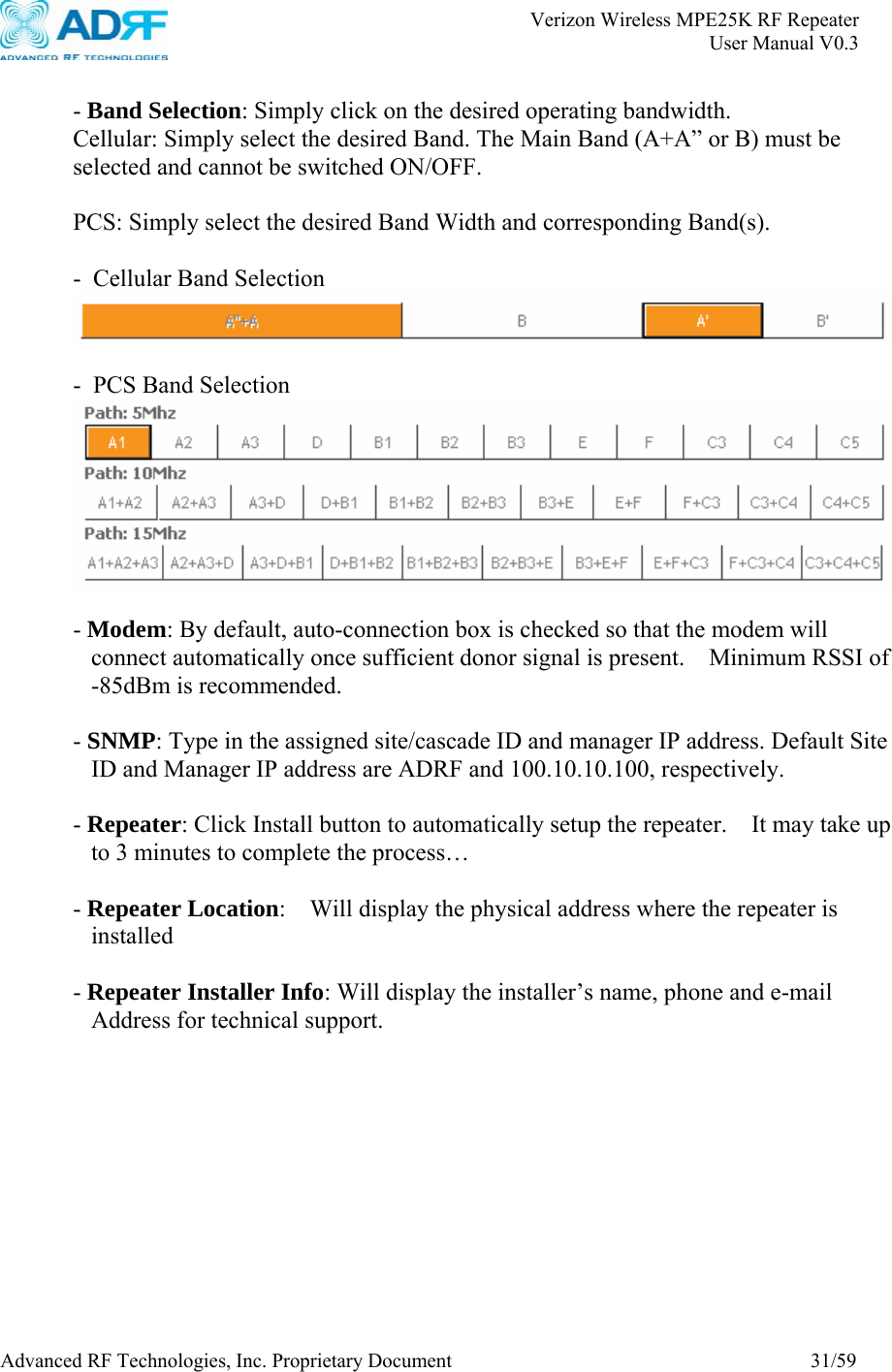
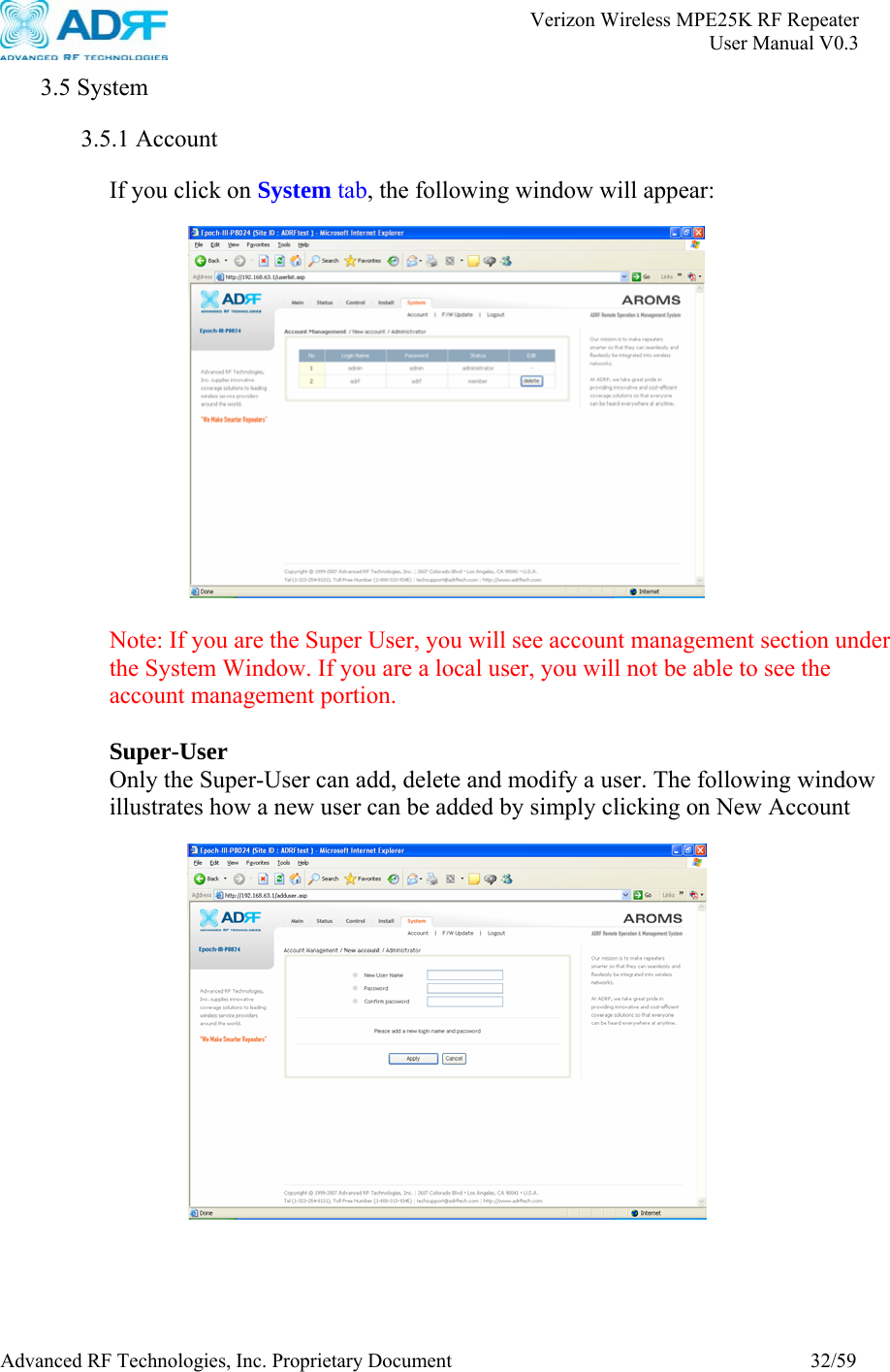
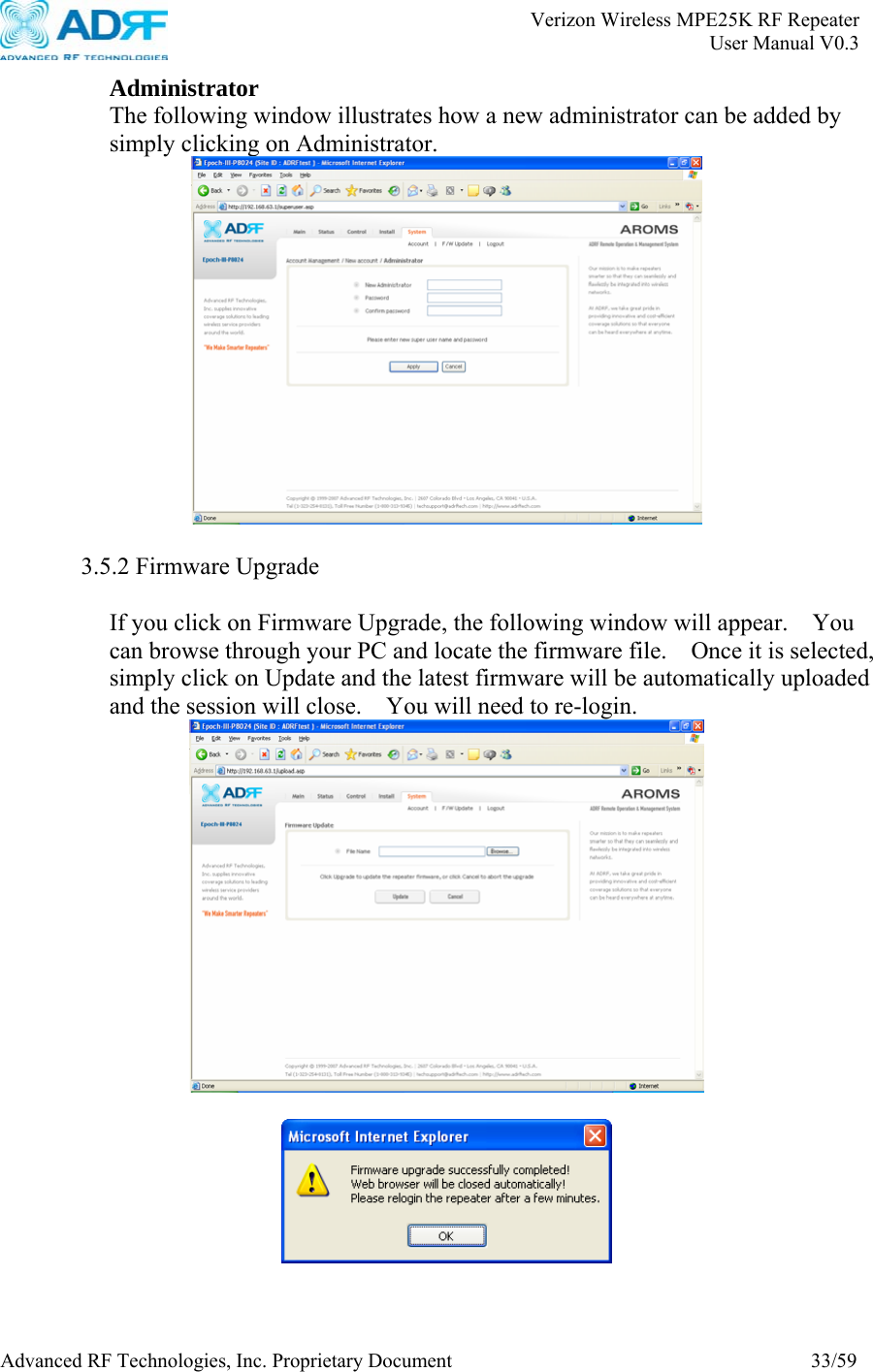
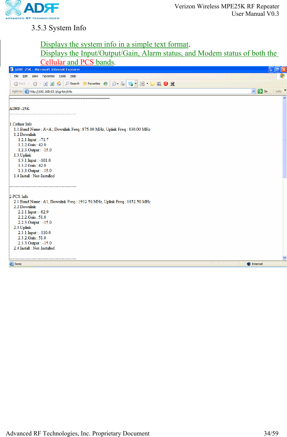
![Verizon Wireless MPE25K RF Repeater User Manual V0.3 Advanced RF Technologies, Inc. Proprietary Document 6/59 1. ADRF-25K 1.1 Introduction Dual bands in one body: ADRF-25K is an over-the-air repeater system that operates in both the Cellular (824 - 894 MHz) and PCS (1850 – 1990 MHz) frequencies. It has one input and one output port. 1.1.1 Highlights • Dual band Repeater • Covers the 60 MHz PCS band • Covers the 25MHz Cellular band [A Band or B Band] • Three switchable SAW filters: You can select any contiguous 5, 10, or 15 MHz bandwidth anywhere within the full 60MHz PCS spectrum. •. Total out-of-the-box solution: ADRF-25K has all the necessary parts that you need.The system includes dual band repeater, donor antennas, server antennas, cables and accessories. • EVDO Rev. A: ADRF-25K is fully compatible with EVDO Rev. A • Ec/Io: In order to ensure proper system installation, in addition to the RSSI indicator on the ADRF-25K’s front panel, you can also read Ec/Io values via the user interface program. • Incremental Automatic Shutdown/Resumption Time: ADRF-25K gradually increases the time span between automatic shutdown and resumption before it permanently shuts itself down • AI compatible: ADRF-25K is fully compatible with Applied Innovation’s monitoring system. • Versatility and Usability: ADRF-25K gives total control to the user. Most of the control parameters, e.g., gain, output power, alarm threshold, etc. can be changed using the user interface so that the user can adjust the system perfectly to the given RF environment. At the same time, due to its intuitive user interface, the user won’t even need to read the manual to get a grip of the system. • 81 ± 2 dB gain @ PCS, 72 ± 2 dB gain @ Cellular • 30 dB AGC Range @ 0.5 dB Step • Sharp out-of-band rejection; 50 dBc @ ±1.5 MHz from the Cellular Sub-band edge , 50 dBc @ ±1 MHz from the PCS Sub-band edge • Supports DHCP; No 3rd party GUI software required • Automated installation](https://usermanual.wiki/Advanced-RF-Technologies/ADRF25K/User-Guide-996468-Page-6.png)
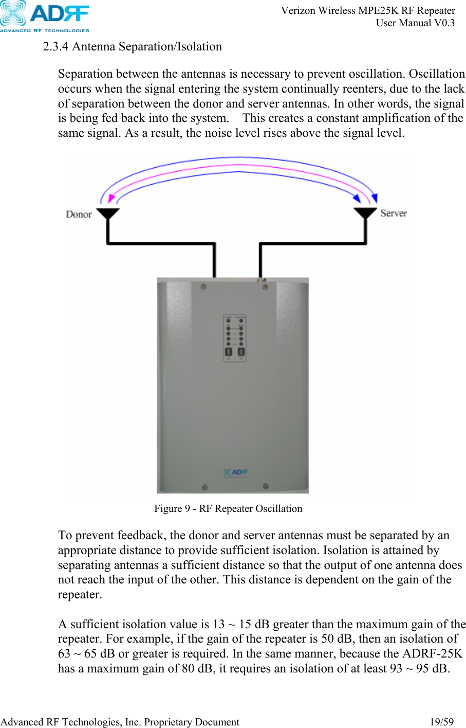
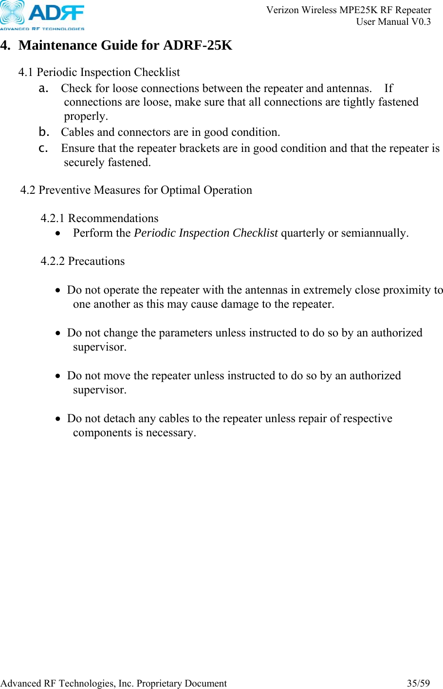
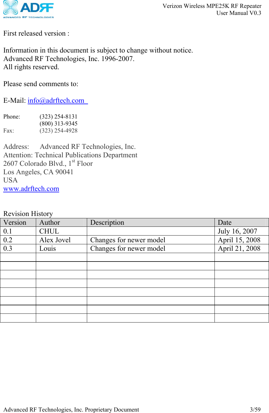
![Verizon Wireless MPE25K RF Repeater User Manual V0.3 Advanced RF Technologies, Inc. Proprietary Document 38/59 Appendix A: Specifications A.1 Electrical Specifications Specifications Parameters Downlink Uplink Remark Cellular A band [(A+A”)=A+A’] 869.0~880.0 MHz 890.0~891.5 MHz 824.0~835.0 MHz, 845.0~846.5 MHz Cellular B band (B+B’) 880.0~890.0 MHz 891.5~894.0 MHz 835.0~845.0 MHz, 846.5~849.0 MHz Configurable Frequency PCS 1930.0~1990.0 MHz 1850.0~1910.0 MHz Cellular A(A+A”) + A’ or B + B’ (Configurable) A’ or B’ spectrum on/off Sub Band Filtering PCS 5, 10 or 15 MHz BW (Tunable) contiguous band Cellular >45dBc@±2MHz from the sub-band edge A,B Roll off PCS >45dBc@±1.5MHz from the sub-band edge. Spurious Emissions 3.6 and 4.5 of [1], 3.8 and 4.4 of [2] Radiated Spurious Emissions Part15.109, part 22.917, part24.238 Cellular 43+10log(p)dB or 26dB (greater of the two) P : Maximum Output( W) RBW 100 KHz or 1% of Emission BW Out of band emissions [3] PCS 43+10log(p)dB or 26dB (greater of the two) P : Maximum Output (W) RBW 1 MHz or 1% of Emission BW Downlink -105~-55dBm(EIRP) Input Uplink Cellular ≤ +20 dBm ≤ +17 dBm PCS ≤ +20 dBm ≤ +17 dBm EIRP Cellular ≤ +15 dBm ≤ +10 dBm Output PCS ≤ +18 dBm ≤ +12 dBm Repeater Only Cellular 72 ± 2 dB 72 ± 2 dB Gain PCS 81 ± 2 dB 81 ± 2 dB Repeater Only ≤ ±1.5dB across the Cellular and PCS bands Typ: ±1.25 Gain flatness ≤ ±2dB at all temperature range](https://usermanual.wiki/Advanced-RF-Technologies/ADRF25K/User-Guide-996468-Page-38.png)
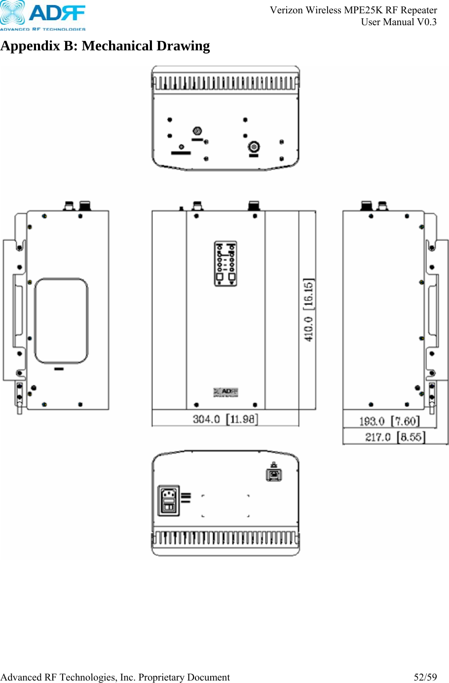
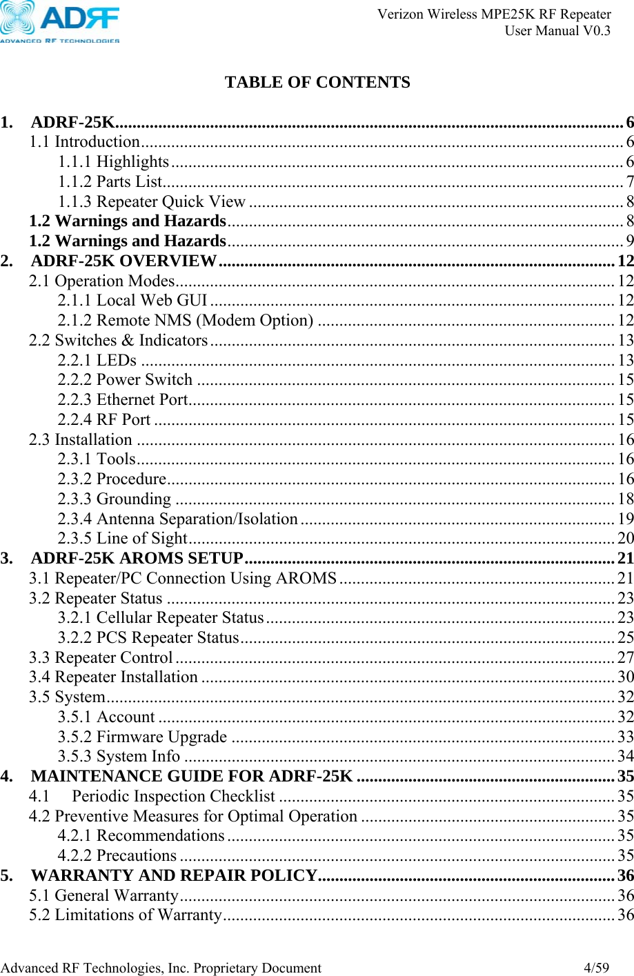
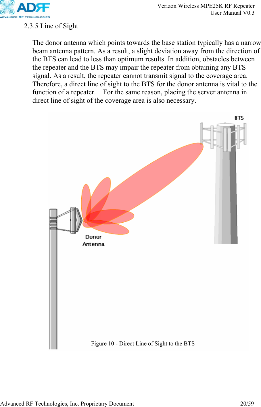
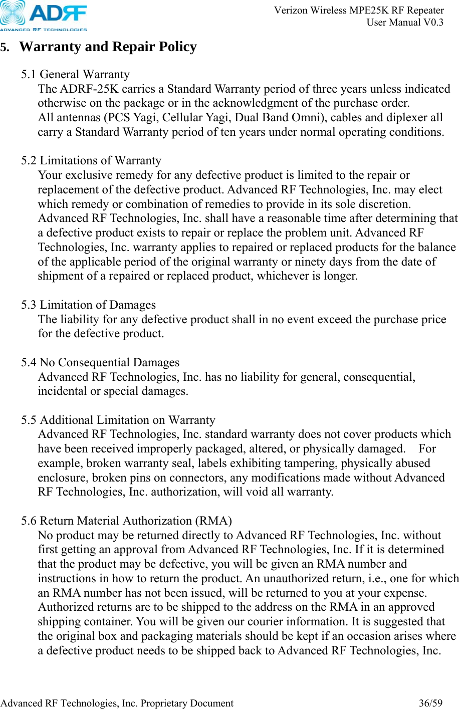
![Verizon Wireless MPE25K RF Repeater User Manual V0.3 Advanced RF Technologies, Inc. Proprietary Document 39/59 Cellular ≥ 30 dB Gain Control Range PCS ≥ 30 dB Cellular - 5 ~ + 15 dBm - 10 ~ + 10 dBm AGC Setting Range PCS - 2 ~ + 18 dBm - 8 ~ + 12 dBm Repeater Only EVDO Gain Offset -3 ~ +3dB, @ 0.5 dB Step Cellular ≤ 8.5dB @ Max Gain≤ 9.5dB @ Min Gain ≤ 7.0dB @ Max Gain ≤ 8.0dB @ Min Gain Repeater Only Noise Figure PCS ≤ 7.5dB @ Max Gain≤ 8.5dB @ Min Gain ≤ 7.0dB @ Max Gain ≤ 8.0dB @ Min Gain Repeater Only PCS ≤ 5 us Delay Cellular ≤ 5 us Phase error 3° RMS Frequency error ± 300 Hz for Cellular, ± 150 Hz for PCS Magnitude error < 5% Rho factor > 0.912 Signal Quality IQ imbalance < 0.35% VSWR <1:1.5 Input ports [1] TIA/EIA-98-F, “Recommended Minimum Performance Standards for CDMA2000 Spread Spectrum Mobile Stations” [2] TIA/EIA-97-F, “Recommended Minimum Performance Standards for CDMA2000 Spread Spectrum Base Stations” [3] FCC CFR Title 47, part22 for Cellular, part24 for PCS A.2 General Specifications Parameters Specifications Remark Dimension ( W × D × H ) 304×410×193mm (11.98 × 16.15 × 7.6 inches ) Weight( lbs ) 18.5 Kg ( 40.78 lbs ) Storage -4 ~ 158°F -20 ~ +70°C Temperature Operating 14 ~ 122°F -10 ~ +50°C Humidity 5 ~ 85%, non condensing AC power 100~120 VAC, 50~60 Hz Power Consumption ≤ 90 W (PCS + Cellular ) Water IP40 Wireless Modem 3G Modem Local RJ45 (DHCP) NMS Remote SNMP](https://usermanual.wiki/Advanced-RF-Technologies/ADRF25K/User-Guide-996468-Page-39.png)