Advanced RF Technologies ADRF25K Dual Band (PCS & Cellular) bi-directional amplifier User Manual Manual
Advanced RF Technologies, Inc. Dual Band (PCS & Cellular) bi-directional amplifier Manual
Manual
Verizon Wireless ADRF-25K
USER MANUAL
Version 0.3
2607 Colorado Blvd.
Los Angeles, CA 90041
USA
Tel: 323-254-8131
Fax: 323-254-4928
www.adrftech.com

Verizon Wireless MPE25K RF Repeater
User Manual V0.3
Advanced RF Technologies, Inc. Proprietary Document 2/59
Glossary
The following is a list of abbreviations and terms used throughout this document.
Abbreviation/Term Definition
AGC Automatic Gain Control
ALC Automatic Level Control
AROMS ADRF’ Repeater Operation and Management
System
BTS Base Transceiver Station
CDMA Code Division Multiple Access
CFE Compact Front End
CW Continuous Wave (un-modulated signal)
DAS Distributed Antenna System
DL Downlink
Downlink The path covered from the Base Transceiver
Station (BTS) to the subscribers service area
via the repeater
HPA High Power Amplifier
HW Hardware
IF Intermediate Frequency
LNA Low Noise Amplifier
MS Mobile Station
PLL Phased Locked Loop
PS Power Supply
RF Radio Frequency
SQE Signal Quality Estimate
SW Software
UL Uplink
Uplink The path covered from the subscribers service
area to the Base Transceiver Station(BTS) via
the repeater
VSWR Voltage Standing Wave Ratio
Verizon Wireless MPE25K RF Repeater
User Manual V0.3
Advanced RF Technologies, Inc. Proprietary Document 3/59
First released version :
Information in this document is subject to change without notice.
Advanced RF Technologies, Inc. 1996-2007.
All rights reserved.
Please send comments to:
E-Mail: info@adrftech.com
Phone: (323) 254-8131
(800) 313-9345
Fax: (323) 254-4928
Address: Advanced RF Technologies, Inc.
Attention: Technical Publications Department
2607 Colorado Blvd., 1st Floor
Los Angeles, CA 90041
USA
www.adrftech.com
Revision History
Version Author Description Date
0.1 CHUL July 16, 2007
0.2 Alex Jovel Changes for newer model April 15, 2008
0.3 Louis Changes for newer model April 21, 2008

Verizon Wireless MPE25K RF Repeater
User Manual V0.3
Advanced RF Technologies, Inc. Proprietary Document 4/59
TABLE OF CONTENTS
1. ADRF-25K......................................................................................................................6
1.1 Introduction................................................................................................................6
1.1.1 Highlights......................................................................................................... 6
1.1.2 Parts List........................................................................................................... 7
1.1.3 Repeater Quick View ....................................................................................... 8
1.2 Warnings and Hazards............................................................................................ 8
1.2 Warnings and Hazards............................................................................................ 9
2. ADRF-25K OVERVIEW............................................................................................12
2.1 Operation Modes...................................................................................................... 12
2.1.1 Local Web GUI .............................................................................................. 12
2.1.2 Remote NMS (Modem Option) .....................................................................12
2.2 Switches & Indicators.............................................................................................. 13
2.2.1 LEDs .............................................................................................................. 13
2.2.2 Power Switch ................................................................................................. 15
2.2.3 Ethernet Port................................................................................................... 15
2.2.4 RF Port ........................................................................................................... 15
2.3 Installation ............................................................................................................... 16
2.3.1 Tools............................................................................................................... 16
2.3.2 Procedure........................................................................................................ 16
2.3.3 Grounding ...................................................................................................... 18
2.3.4 Antenna Separation/Isolation ......................................................................... 19
2.3.5 Line of Sight................................................................................................... 20
3. ADRF-25K AROMS SETUP......................................................................................21
3.1 Repeater/PC Connection Using AROMS ................................................................ 21
3.2 Repeater Status ........................................................................................................ 23
3.2.1 Cellular Repeater Status................................................................................. 23
3.2.2 PCS Repeater Status....................................................................................... 25
3.3 Repeater Control ...................................................................................................... 27
3.4 Repeater Installation ................................................................................................ 30
3.5 System......................................................................................................................32
3.5.1 Account .......................................................................................................... 32
3.5.2 Firmware Upgrade .........................................................................................33
3.5.3 System Info .................................................................................................... 34
4. MAINTENANCE GUIDE FOR ADRF-25K ............................................................35
4.1 Periodic Inspection Checklist .............................................................................. 35
4.2 Preventive Measures for Optimal Operation ........................................................... 35
4.2.1 Recommendations .......................................................................................... 35
4.2.2 Precautions ..................................................................................................... 35
5. WARRANTY AND REPAIR POLICY.....................................................................36
5.1 General Warranty..................................................................................................... 36
5.2 Limitations of Warranty........................................................................................... 36

Verizon Wireless MPE25K RF Repeater
User Manual V0.3
Advanced RF Technologies, Inc. Proprietary Document 5/59
5.3 Limitation of Damages ............................................................................................ 36
5.4 No Consequential Damages..................................................................................... 36
5.5 Additional Limitation on Warranty ......................................................................... 36
5.6 Return Material Authorization (RMA) .................................................................... 36
APPENDIX A: SPECIFICATIONS .................................................................................38
A.1 Electrical Specifications.......................................................................................... 38
A.2 General Specifications ............................................................................................ 39
A.3 Power Supply Specifications .................................................................................. 40
A.4 Antenna Specifications ........................................................................................... 41
A.4.1 Server Antenna.............................................................................................. 41
A.4.2 PCS Donor Yagi Antenna ............................................................................. 44
A.4.3 Cellular Donor Yagi Antenna ....................................................................... 47
A.5 Diplexer Module Specifications ............................................................................. 50
A.6 Cable Specifications................................................................................................ 49
APPENDIX B: MECHANICAL DRAWING..................................................................52
APPENDIX C: ADRF-25K OVERVIEW........................................................................53
C.1 Block Diagram ........................................................................................................ 53
C.1 Components............................................................................................................. 54

Verizon Wireless MPE25K RF Repeater
User Manual V0.3
Advanced RF Technologies, Inc. Proprietary Document 6/59
1. ADRF-25K
1.1 Introduction
Dual bands in one body: ADRF-25K is an over-the-air repeater system that
operates in both the Cellular (824 - 894 MHz) and PCS (1850 – 1990 MHz)
frequencies. It has one input and one output port.
1.1.1 Highlights
• Dual band Repeater
• Covers the 60 MHz PCS band
• Covers the 25MHz Cellular band [A Band or B Band]
• Three switchable SAW filters: You can select any contiguous 5, 10, or 15
MHz bandwidth anywhere within the full 60MHz PCS spectrum.
•. Total out-of-the-box solution: ADRF-25K has all the necessary parts that you
need.The system includes dual band repeater, donor antennas, server antennas,
cables and accessories.
• EVDO Rev. A: ADRF-25K is fully compatible with EVDO Rev. A
• Ec/Io: In order to ensure proper system installation, in addition to the RSSI
indicator on the ADRF-25K’s front panel, you can also read Ec/Io values via
the user interface program.
• Incremental Automatic Shutdown/Resumption Time: ADRF-25K gradually
increases the time span between automatic shutdown and resumption before it
permanently shuts itself down
• AI compatible: ADRF-25K is fully compatible with Applied Innovation’s
monitoring system.
• Versatility and Usability: ADRF-25K gives total control to the user. Most of
the control parameters, e.g., gain, output power, alarm threshold, etc. can be
changed using the user interface so that the user can adjust the system
perfectly to the given RF environment. At the same time, due to its intuitive
user interface, the user won’t even need to read the manual to get a grip of the
system.
• 81 ± 2 dB gain @ PCS, 72 ± 2 dB gain @ Cellular
• 30 dB AGC Range @ 0.5 dB Step
• Sharp out-of-band rejection; 50 dBc @ ±1.5 MHz from the Cellular Sub-band
edge , 50 dBc @ ±1 MHz from the PCS Sub-band edge
• Supports DHCP; No 3rd party GUI software required
• Automated installation
Verizon Wireless MPE25K RF Repeater
User Manual V0.3
Advanced RF Technologies, Inc. Proprietary Document 7/59
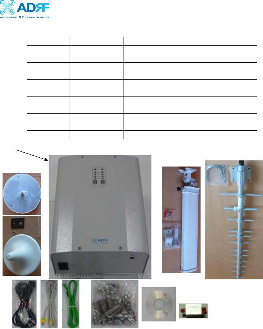
1.1.2 Parts List
Label Qty Description
A 1 ADRF-25K Repeater
B 1 AC Power Cable
C 1 Ethernet Cable (Crossover)
D 1 Ground Cable
E 4 Anchor Bolts & Mount Screw
F 1 CD
G 1 Diplexer Module
H 1 PCS Donor Antenna
I 1 Cellular Donor Antenna
J 1 Dual OMNI Antenna
---- 4 RF Coaxial Cable
** CD also included: (1)ADRF-25K User Manual & (1)ADRF-25K Quick Start Guide
Figure 1 – ADRF-25K Repeater Parts List
Table 1
–
Parts Lis
t
A
C ED F
G
B
H
I
J
Verizon Wireless MPE25K RF Repeater
User Manual V0.3
Advanced RF Technologies, Inc. Proprietary Document 8/59
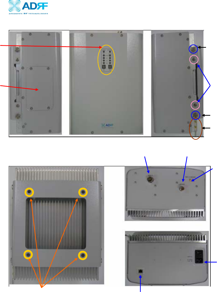
1.1.3 Repeater Quick View
Figure 2 ADRF-25K Front & Side Views
Display LED
(Page12)
Modem
Ground Hole
(Page17)
Bracket Screw
(Page16)
Upper Guard Screw
(Page16)
Lower Guard Screw
(Page16)
Figure 3 – ADRF-25K Back & Bottom Views
Anchor Bolt
Hole (page16)
Donor Antenna Port
(Page14)
Server1 Antenna Port
(Page14) Server2 Antenna Port
(Page14)
Power switch
(page14)
Ethernet Port (page14)
Verizon Wireless MPE25K RF Repeater
User Manual V0.3
Advanced RF Technologies, Inc. Proprietary Document 9/59
1.2 Warnings and Hazards
Actual separation distance is determined upon gain of antenna used.
Please maintain a minimum safe distance of at least 20 cm while operating near the donor and the server
antennas. Also, the donor antenna needs to be mounted outdoors on a permanent structure.
RF EXPOSURE & ANTENNA PLACEMENT Guidelines
Opening or tampering the ADRF-25K will void all warranties.
WARRANTY
Y
Operating the ADRF-25K with antennas in very close proximity facing each other
could lead to severe damage to the repeater.
WARNING! DAMAGE TO REPEATER
Working with the repeater while in operation, may expose the technician to RF
electromagnetic fields that exceed FCC rules for human exposure. Visit the FCC
website at www.fcc.gov/oet/rfsafety to learn more about the effects of exposure to
RF electromagnetic fields.
WARNING! EXPOSURE TO RF
Opening the ADRF-25K could result in electric shock and may
cause severe injury.
WARNING! ELECTRIC SHOCK
Verizon Wireless MPE25K RF Repeater
User Manual V0.3
Advanced RF Technologies, Inc. Proprietary Document 10/59
NOTE: This equipment has been tested and found to comply with the limits for a
Class A digital device, pursuant to part 15 of the FCC Rules. These limits are
designed to provide reasonable protection against harmful interference when the
equipment is operated in a commercial environment. This equipment generates,
uses, and can radiate radio frequency energy and, if not installed and used in
accordance with the instruction manual, may cause harmful interference to radio
communications. Operation of this equipment in a residential area is likely to
cause harmful interference in which case the user will be required to correct the
interference at his own expense.
FCC Part 15 Class A
Lithium Battery : CAUTION. RISK OF EXPLOSION IF BATTERY IS REPLACED BY
INCORRECT TYPE. DISPOSE OF USED BATTERIES ACCORDING TO INSTRUCTIONS.
Ethernet Instructions: This equipment is for indoor use only. All cabling should be
limited to inside the building.

Verizon Wireless MPE25K RF Repeater
User Manual V0.3
Advanced RF Technologies, Inc. Proprietary Document 11/59
This Class A digital apparatus complies with Canadian ICES-003.
Cet appareil numérique de la classe A est conforme à la norme NMB-003 du Canada.
Operation is subject to the following two conditions: (1) this device may not cause
interference, and (2) this device must accept any interference, including interference
that may cause undesired operation of the device.
To reduce potential radio interference to other users, the antenna type and its gain
should be so chosen that the equivalent isotropically radiated power (E.I.R.P.) is not
more than that permitted for successful communication.
This device has been designed to operate with antennas having a maximum gain of
18 dBi. Antennas having a gain greater than 18 dBi are strictly prohibited for use with
this device. The required antenna impedance is 50 ohms.
Industr
y
Canada

Verizon Wireless MPE25K RF Repeater
User Manual V0.3
Advanced RF Technologies, Inc. Proprietary Document 12/59
2. ADRF-25K Overview
2.1 Operation Modes
2.1.1 Local Web GUI
Turn on the power switch of the ADRF-25K. Wait until the Power LED on the
front panel is lit in green. Simply connect one end of the Ethernet cable on one
of the three repeater monitor Ethernet ports and the other end on the PC’s LAN
port. Launch the Microsoft Internet Browser (Internet Explorer) and type in
the IP address (http://192.168.63.1). The Local Web GUI will be launched.
For more detailed instructions on how to connect your laptop to the ADRF-25K,
go to Chapter 3.
2.1.2 Remote NMS (Modem Option)
A CDMA wireless modem can be integrated within the ADRF-25K repeater.
With this wireless modem, the user can remotely log into the repeater for
monitoring purposes.
Verizon Wireless MPE25K RF Repeater
User Manual V0.3
Advanced RF Technologies, Inc. Proprietary Document 13/59
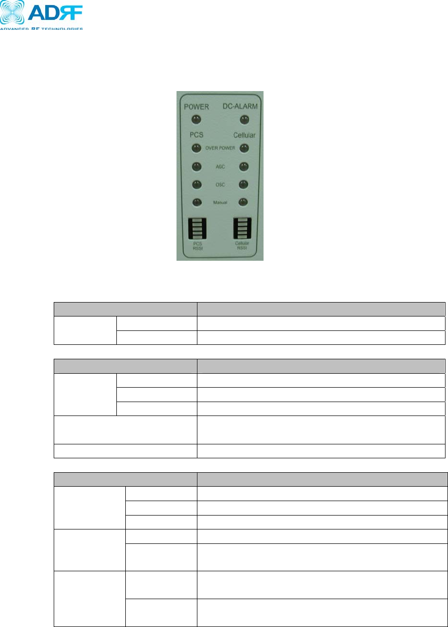
2.2 Switches & Indicators
2.2.1 LEDs
ADRF-25K has LEDs on the front panel of the repeater as shown below in
Figure 4.
z POWER LED
Parameters Specifications
Repeater On Green LED on LED
Repeater Off Green LED off
z DC-ALARM LED
Parameters Specifications
Normal Red LED off
Soft fail Green LED on
LED
Hard fail Red LED on
Condition for Alarm
Activation
Current > 9A (Hard Fail)
Current < 2A (Soft Fail)
After Alarm Activation Full Spectrum (PCS/Cellular) shutdown
z OVER POWER LED
Parameters Specifications
Normal LED off
Soft fail PCS(Cellular) Green LED on
LED
Hard fail PCS(Cellular) Red LED on
Soft fail Max power +1 <measured output < max power+2 Condition
for Alarm
Activation
Hard fail measured output > max power + 2
Soft fail Only the alarm is activated and the repeater
operates as normal
Following
Alarm
Activation Hard fail The function associated with the alarm shuts
down, and the shutdown process goes into effect
Figure 4 – ADRF25K Repeater LED View
Verizon Wireless MPE25K RF Repeater
User Manual V0.3
Advanced RF Technologies, Inc. Proprietary Document 14/59
z AGC LED
Parameters Specifications
AGC On PCS(Cellular) Green LED On LED
AGC Off PCS(Cellular) Green LED Off
z OSC LED
Parameters Specifications
Normal Red LED off LED
Hard fail Red LED on
Condition for Alarm
Activation
Repeater goes into oscillation
Following Alarm
Activation
The portion associated with the oscillation shuts
down, and at time of oscillation the defined
procedure goes into effect
z MANUAL LED
Parameters Specifications
Manually
HPA Off/On
PCS(Cellular) Green LED On LED
Factory set or
Reboot
PCS(Cellular) Green LED Off
z RSSI LED BAR
Parameters Specifications
Input < -95dBm PCS(Cellular) All LED Off
Input < -85dBm PCS(Cellular) one LED On
Input < -75dBm PCS(Cellular) two LED On
Input < -65dBm PCS(Cellular) three LED On
Input < -55dBm PCS(Cellular) four LED On
LED
Input > -55dBm PCS(Cellular) five LED On
Verizon Wireless MPE25K RF Repeater
User Manual V0.3
Advanced RF Technologies, Inc. Proprietary Document 15/59
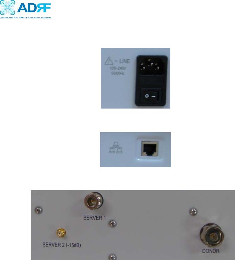
2.2.2 Power Switch
The AC Power on/off switch is located at the bottom of repeater. The switch
should be powered on after the repeater has been installed properly.
2.2.3 Ethernet Port
2.2.4 RF Port
- Donor:
Connect the COM port of the diplexer
- Server 1
Connect the Server antenna
- Server 2
For use with an auxiliary server antenna. Signal is attenuated by -15dBm compared to
Server1.
Figure 5 – ADRF-25K Repeater Power Switch View
Figure 6 – Ethernet Port

Verizon Wireless MPE25K RF Repeater
User Manual V0.3
Advanced RF Technologies, Inc. Proprietary Document 16/59
2.3 Installation
2.3.1 Tools
No special tools or equipment are needed to install the ADRF-25K.
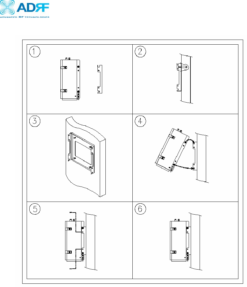
2.3.2 Procedure
Four mounting holes are located on the wall-mounting bracket to attach it to the
wall. The wall bracket must be securely attached to sufficiently carry the weight
of the ADRF-25K, which is bolted to the wall bracket through the four aligned
mounting holes.
The following steps should be followed while mounting the repeater:
Installation Procedure
① Verify that the Repeater and Mounting Bracket are in good condition.
② Drill holes in the installation surface and insert the anchor bolts.
③ Set the mounting bracket against the wall.
④ Using the Hooks on top, set the Repeater against the mounting bracket.
⑤ Using the anchor bolts attach the Repeater to the Bracket.
⑥ Make sure the Repeater is securely attached.
⑦ Connect the GND cable.
⑧ Connect the Antenna cable.
⑨ Connect the Power.
⑩ Using a laptop, install the Repeater.
Verizon Wireless MPE25K RF Repeater
User Manual V0.3
Advanced RF Technologies, Inc. Proprietary Document 17/59
Figure 7 – Repeater Mounting Instructions
Verizon Wireless MPE25K RF Repeater
User Manual V0.3
Advanced RF Technologies, Inc. Proprietary Document 18/59
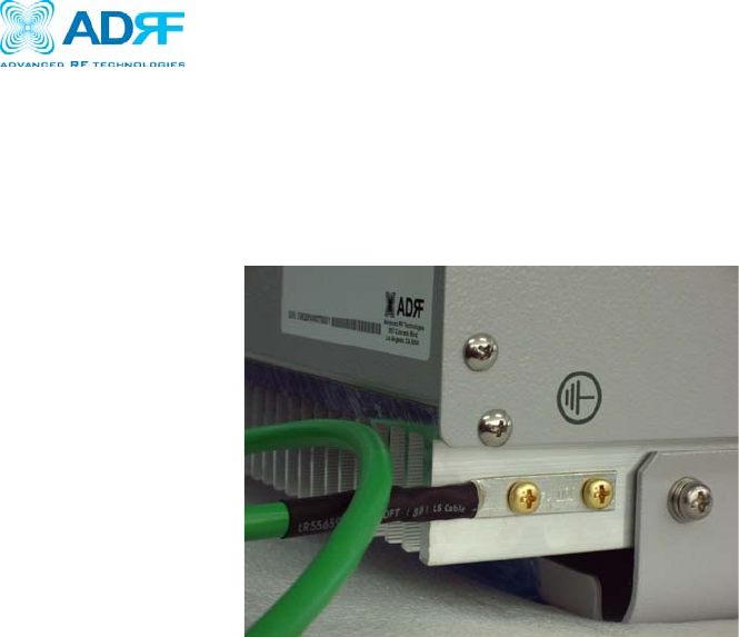
2.3.3 Grounding
A ground cable is included in the box. The ground cable should be connected to
the ADRF-25K before the repeater is turned on.
Figure 8 – Ground Cable Connection
Verizon Wireless MPE25K RF Repeater
User Manual V0.3
Advanced RF Technologies, Inc. Proprietary Document 19/59
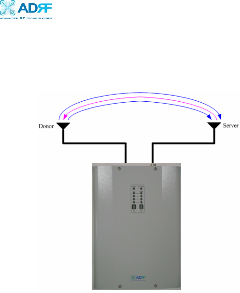
2.3.4 Antenna Separation/Isolation
Separation between the antennas is necessary to prevent oscillation. Oscillation
occurs when the signal entering the system continually reenters, due to the lack
of separation between the donor and server antennas. In other words, the signal
is being fed back into the system. This creates a constant amplification of the
same signal. As a result, the noise level rises above the signal level.
To prevent feedback, the donor and server antennas must be separated by an
appropriate distance to provide sufficient isolation. Isolation is attained by
separating antennas a sufficient distance so that the output of one antenna does
not reach the input of the other. This distance is dependent on the gain of the
repeater.
A sufficient isolation value is 13 ~ 15 dB greater than the maximum gain of the
repeater. For example, if the gain of the repeater is 50 dB, then an isolation of
63 ~ 65 dB or greater is required. In the same manner, because the ADRF-25K
has a maximum gain of 80 dB, it requires an isolation of at least 93 ~ 95 dB.
Figure 9 - RF Repeater Oscillation
Verizon Wireless MPE25K RF Repeater
User Manual V0.3
Advanced RF Technologies, Inc. Proprietary Document 20/59
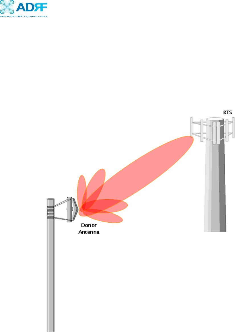
2.3.5 Line of Sight
The donor antenna which points towards the base station typically has a narrow
beam antenna pattern. As a result, a slight deviation away from the direction of
the BTS can lead to less than optimum results. In addition, obstacles between
the repeater and the BTS may impair the repeater from obtaining any BTS
signal. As a result, the repeater cannot transmit signal to the coverage area.
Therefore, a direct line of sight to the BTS for the donor antenna is vital to the
function of a repeater. For the same reason, placing the server antenna in
direct line of sight of the coverage area is also necessary.
Figure 10 - Direct Line of Sight to the BTS

Verizon Wireless MPE25K RF Repeater
User Manual V0.3
Advanced RF Technologies, Inc. Proprietary Document 21/59
3. ADRF-25K AROMS Setup
3.1 Repeater/PC Connection Using AROMS
i) Wait until the Power LED is lit in green. Connect the LAN cable between the
laptop’s Ethernet port and the repeater’s Ethernet port.
Note: Under Local Area Connection in Network Settings, make sure to select
Obtain an IP address automatically under Internet Protocol (TCP/IP) properties.
ii) Launch MS Internet Explorer (Version 6.0 or higher)
Note: ADRF’s Web GUI is not compatible with any other web browsers (e.g.
Netscape, FireFox, Mozilla, etc.).
iii) Please type the following IP address into the address bar of MS Internet
Explorer:
http://192.168.63.1
Verizon Wireless MPE25K RF Repeater
User Manual V0.3
Advanced RF Technologies, Inc. Proprietary Document 22/59
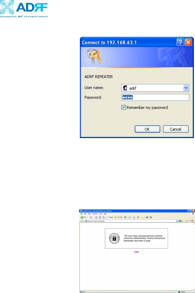
iv) The following login screen will appear:
If you are not the Super-User, please type in your assigned username & password
which you should have received from the Super-User.
The default username and password for the General User is adrf & adrf, respectively.
If the username & password is typed in incorrectly, the following screen will
appear:
Verizon Wireless MPE25K RF Repeater
User Manual V0.3
Advanced RF Technologies, Inc. Proprietary Document 23/59
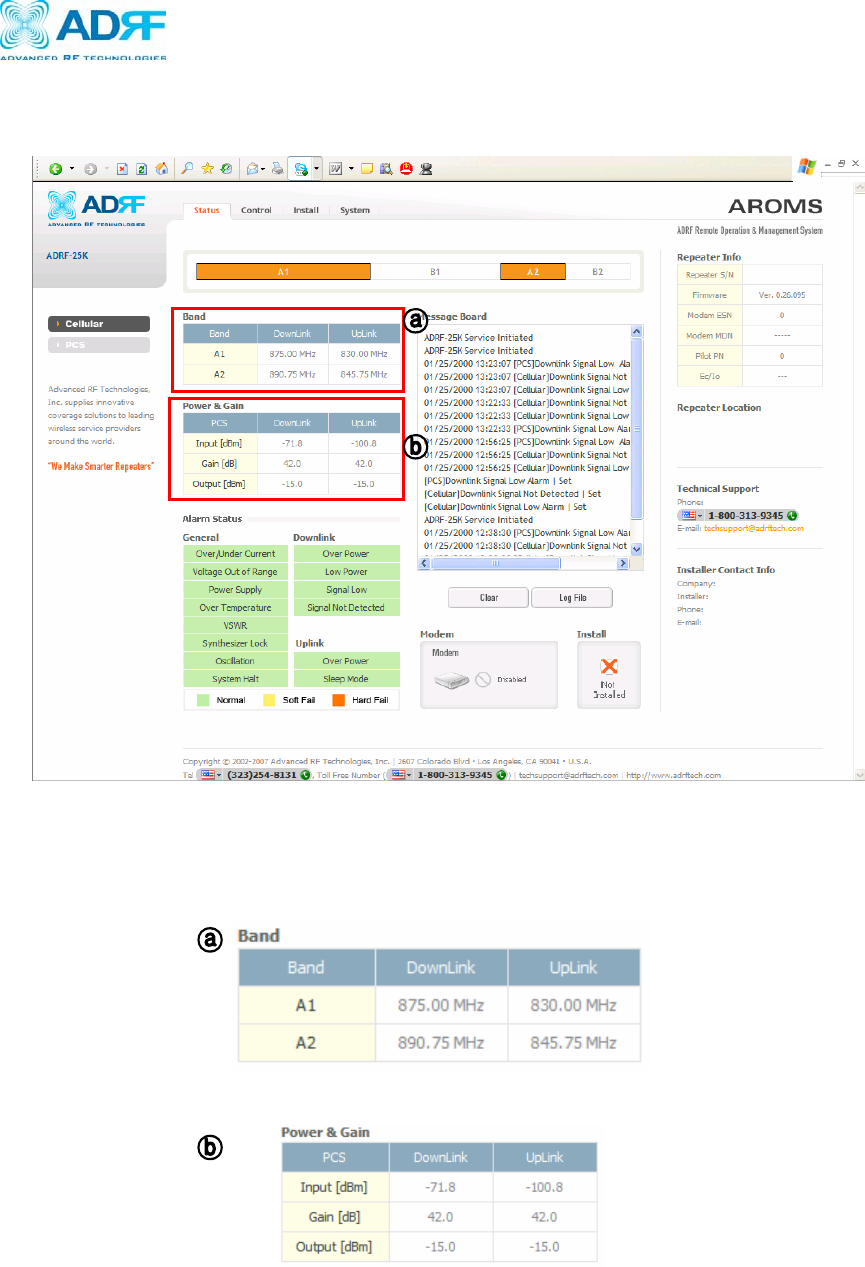
3.2 Repeater Status
3.2.1 Cellular Repeater Status
If you click on Status tab, the following window will appear:
In this window, the user can view the following:
(To change any parameters, e.g., Cellular Band, Gain Settings, you will need to
go to the Install or Control Menu.)
- Cellular Band: Will display the center frequencies of the 800 MHz spectrums
on the downlink and uplink respectively.
- Power & Gain: Will display the repeater input, gain and output power on the
downlink and uplink.

Verizon Wireless MPE25K RF Repeater
User Manual V0.3
Advanced RF Technologies, Inc. Proprietary Document 24/59
- Alarm: Will display eleven alarms with three different status conditions
(Normal, Soft Fail or Hard Fail).
- Message Board: Will show up to recent 20 log messages (Alarms &
Heartbeats).
- Modem: Will display the status of the mode (e.g. Disabled, Not Connected or
Connected)
- Installation: Will display repeater’s installation status (Not Installed or
Installed).
- Repeater Info: Will display repeater’s serial number, modem ESN and MDN.
- Repeater Location: Will display the address where the repeater is installed
- Technical Support: Will display ADRF’s Technical Support contact
information.
- Installer Contact Info: Will display the installer’s name, phone and e-mail
address.
Note: Once successfully logged in, the repeater model name and the site/cascade
ID will be displayed on the top of all the windows (except for the Main
Window).
Verizon Wireless MPE25K RF Repeater
User Manual V0.3
Advanced RF Technologies, Inc. Proprietary Document 25/59
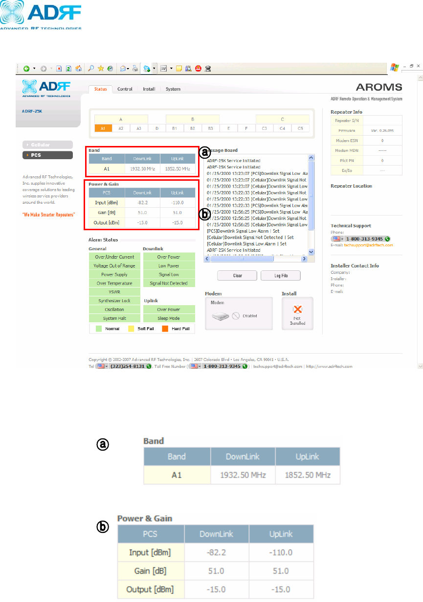
3.2.2 PCS Repeater Status
If you click on Status tab, the following window will appear:
In this window, the user can view the following:
(To change any parameters, e.g., PCS Band, Gain Settings, you will need to go
to the Install or Control Menu.)
- PCS Band: Will display the center frequencies of the 1900 MHz spectrums on
the downlink and uplink respectively.
- Power & Gain: Will display the repeater input, gain and output power on the
downlink and uplink.

Verizon Wireless MPE25K RF Repeater
User Manual V0.3
Advanced RF Technologies, Inc. Proprietary Document 26/59
- Alarm: Will display eleven alarms with three different status conditions
(Normal, Soft Fail or Hard Fail).
- Message Board: Will show up to recent 20 log messages (Alarms &
Heartbeats).
- Modem: Will display the status of the mode (e.g. Disabled, Not Connected or
Connected)
- Installation: Will display repeater’s installation status (Not Installed or
Installed).
- Repeater Info: Will display repeater’s serial number, modem ESN and MDN.
- Repeater Location: Will display the address where the repeater is installed
- Technical Support: Will display ADRF’s Technical Support contact
information.
- Installer Contact Info: Will display the installer’s name, phone and e-mail
address.
Note: Once successfully logged in, the repeater model name and the
site/cascade ID will be displayed on the top of all the windows (except for the
Main Window).
Verizon Wireless MPE25K RF Repeater
User Manual V0.3
Advanced RF Technologies, Inc. Proprietary Document 27/59
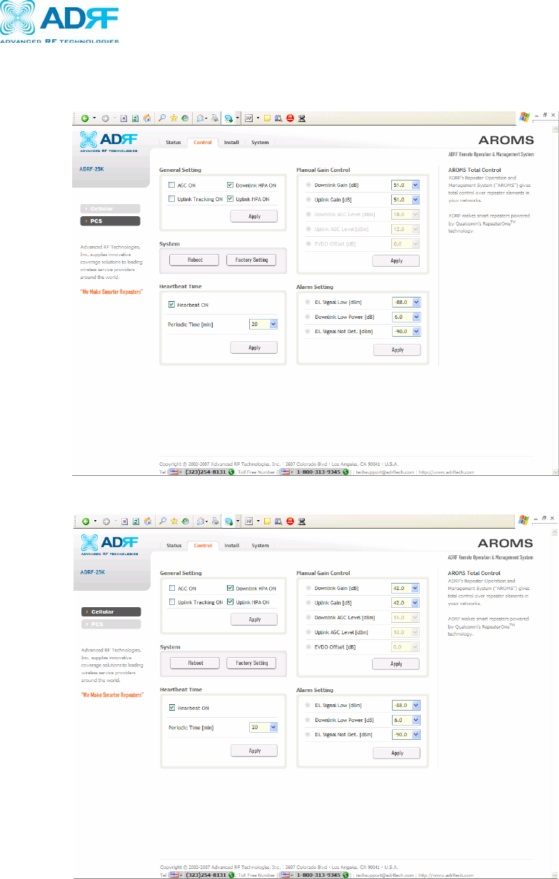
3.3 Repeater Control
If you click on Control window at PCS, the following window will appear
If you click on Control window at Cellular, the following window will appear

Verizon Wireless MPE25K RF Repeater
User Manual V0.3
Advanced RF Technologies, Inc. Proprietary Document 28/59
In this window, the user can adjust the following parameters:
General Setting
- Automatic Gain Control (Default mode is On)
- Downlink HPA on/off (Default mode is On)
- Uplink HPA on/off (Default mode is On)
- Uplink Tracking mode on/off (Default mode is Off)
Manual Gain Control
- Downlink Gain Control
Cellular: 42 to 72 dB @ 0.5 dB step, default value: 72 dB
PCS: 51 to 81 dB @ 0.5 dB step, default value: 81 dB
- Uplink Gain Control
Cellular: 42 to 72 dB @ 0.5 dB step, default value: 72 dB
PCS: 51 to 81 dB @ 0.5 dB step, default value: 81 dB
- Downlink AGC Level
Cellular: -5 to 15 dBm @ 0.5 dB step, default value: 15 dBm
PCS: 1 to 21 dBm @ 0.5 dB step, default value: 21 dBm
- Uplink AGC Level
Cellular: -12 to 8 dBm @ 0.5 dB step, default value: 8 dBm
PCS: -12 to 8 dBm @ 0.5 dB step, default value: 8 dBm
- EVDO Offset
-3 to +3 dB @ 0.5 dB step, default value: 0 dB
When Uplink Tracking is off, the EVDO Offset value is applied and with AGC ON,
the maximum permissible Gain of the Uplink Gain Range is Downlink Gain +
EVDO Offset. However, the gain cannot exceed the standard Max Gain.
When Uplink Tracking is ON, the Tracking Offset is applied and with AGC ON, the
Uplink Gain is the Downlink Gain + EVDO Offset. As expected, the gain cannot
exceed the standard Max Gain.
Verizon Wireless MPE25K RF Repeater
User Manual V0.3
Advanced RF Technologies, Inc. Proprietary Document 29/59
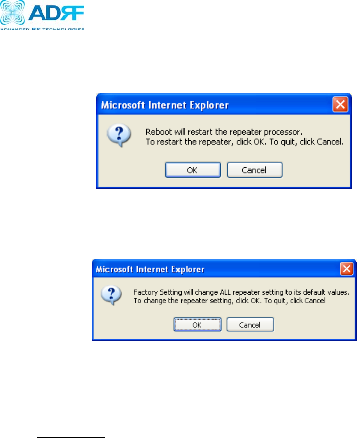
System
-If you click the Reboot button, the following message box will appear:
(When the system reboots, the latest settings will be saved)
-If you click the Factory Setting button, the following message box will appear:
(Factory setting will erase the settings saved by the user and change all the
parameters to the factory default settings)
Heartbeat Time
- Heartbeat on and off (Default mode is Off)
- Heartbeat periodic time (Range: 1 to 59 min @ 1 min step –
Default time is 20 min)
Alarm Setting
- Downlink RSSI Alarm (-110 ~ -30 dBm @ 0.5 dB step –
Default value is -95 dBm)
- Low Power Alarm (2 ~ 10 dB @ 0.5 dB step –
Default value is 6 dB)
Verizon Wireless MPE25K RF Repeater
User Manual V0.3
Advanced RF Technologies, Inc. Proprietary Document 30/59
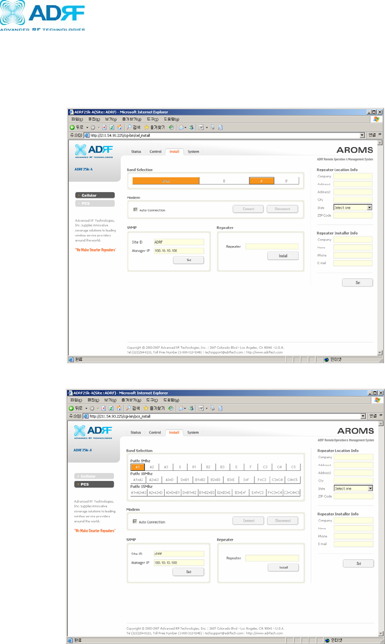
3.4 Repeater Installation
If you click on the Install tab, the following window will appear:
- Cellular Installation Window
- PCS Installation Window
Verizon Wireless MPE25K RF Repeater
User Manual V0.3
Advanced RF Technologies, Inc. Proprietary Document 31/59
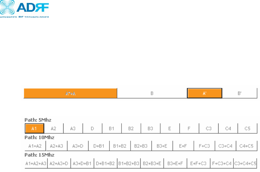
- Band Selection: Simply click on the desired operating bandwidth.
Cellular: Simply select the desired Band. The Main Band (A+A” or B) must be
selected and cannot be switched ON/OFF.
PCS: Simply select the desired Band Width and corresponding Band(s).
- Cellular Band Selection
- PCS Band Selection
- Modem: By default, auto-connection box is checked so that the modem will
connect automatically once sufficient donor signal is present. Minimum RSSI of
-85dBm is recommended.
- SNMP: Type in the assigned site/cascade ID and manager IP address. Default Site
ID and Manager IP address are ADRF and 100.10.10.100, respectively.
- Repeater: Click Install button to automatically setup the repeater. It may take up
to 3 minutes to complete the process…
- Repeater Location: Will display the physical address where the repeater is
installed
- Repeater Installer Info: Will display the installer’s name, phone and e-mail
Address for technical support.
Verizon Wireless MPE25K RF Repeater
User Manual V0.3
Advanced RF Technologies, Inc. Proprietary Document 32/59
3.5 System
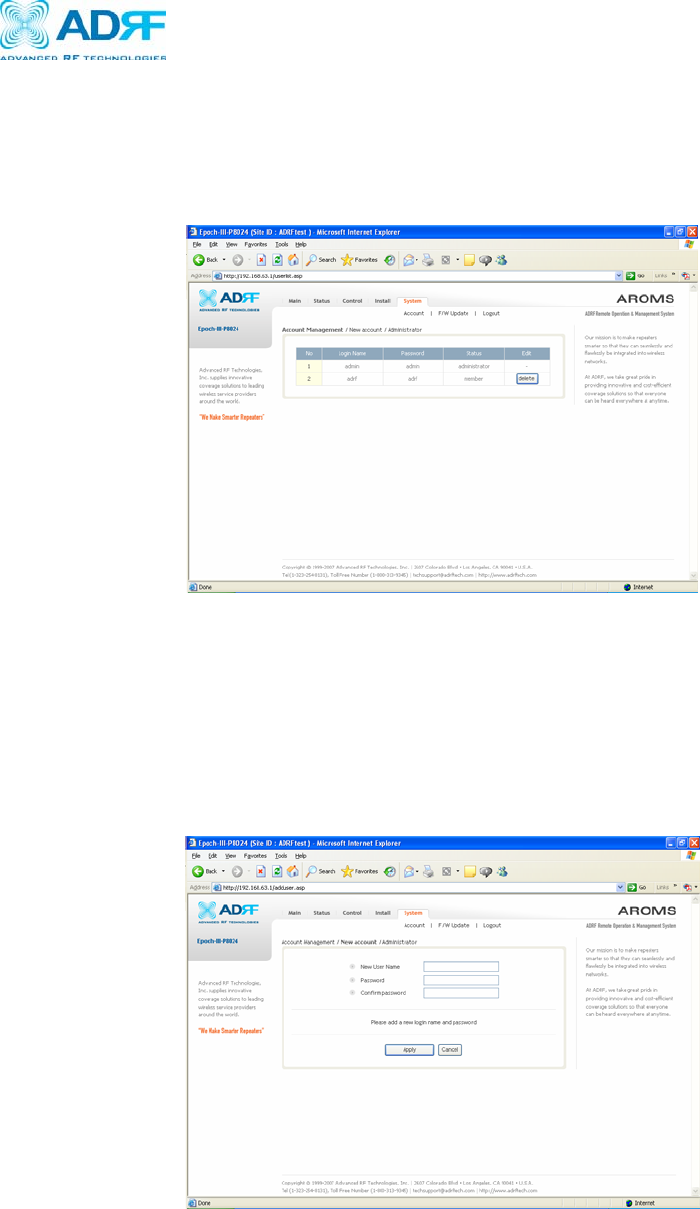
3.5.1 Account
If you click on System tab, the following window will appear:
Note: If you are the Super User, you will see account management section under
the System Window. If you are a local user, you will not be able to see the
account management portion.
Super-User
Only the Super-User can add, delete and modify a user. The following window
illustrates how a new user can be added by simply clicking on New Account
Verizon Wireless MPE25K RF Repeater
User Manual V0.3
Advanced RF Technologies, Inc. Proprietary Document 33/59
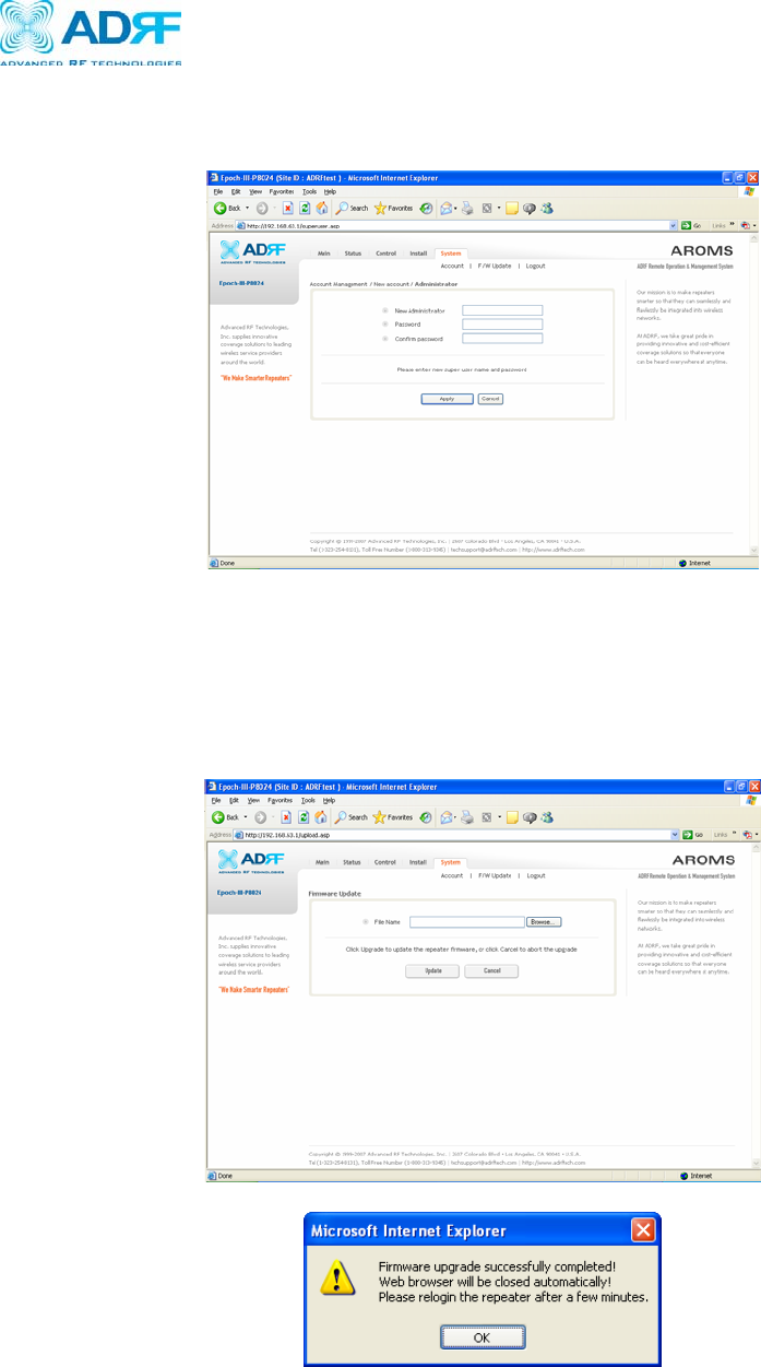
Administrator
The following window illustrates how a new administrator can be added by
simply clicking on Administrator.
3.5.2 Firmware Upgrade
If you click on Firmware Upgrade, the following window will appear. You
can browse through your PC and locate the firmware file. Once it is selected,
simply click on Update and the latest firmware will be automatically uploaded
and the session will close. You will need to re-login.
Verizon Wireless MPE25K RF Repeater
User Manual V0.3
Advanced RF Technologies, Inc. Proprietary Document 34/59
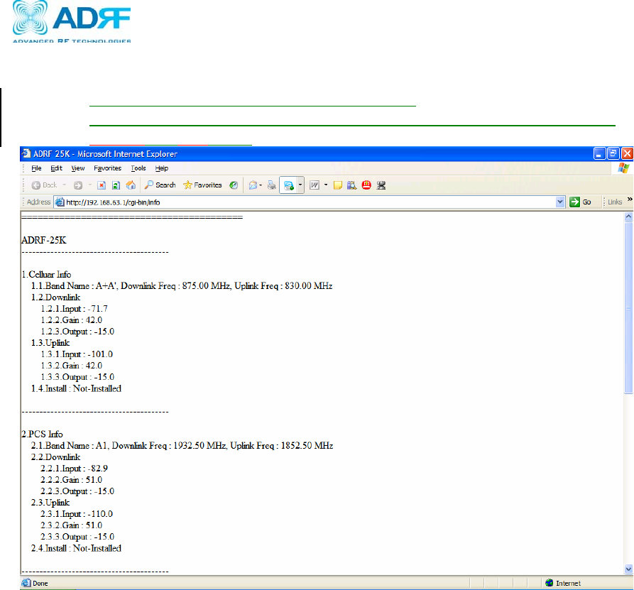
3.5.3 System Info
Displays the system info in a simple text format.
Displays the Input/Output/Gain, Alarm status, and Modem status of both the
Cellular and PCS bands.

Verizon Wireless MPE25K RF Repeater
User Manual V0.3
Advanced RF Technologies, Inc. Proprietary Document 35/59
4. Maintenance Guide for ADRF-25K
4.1 Periodic Inspection Checklist
a. Check for loose connections between the repeater and antennas. If
connections are loose, make sure that all connections are tightly fastened
properly.
b. Cables and connectors are in good condition.
c. Ensure that the repeater brackets are in good condition and that the repeater is
securely fastened.
4.2 Preventive Measures for Optimal Operation
4.2.1 Recommendations
• Perform the Periodic Inspection Checklist quarterly or semiannually.
4.2.2 Precautions
• Do not operate the repeater with the antennas in extremely close proximity to
one another as this may cause damage to the repeater.
• Do not change the parameters unless instructed to do so by an authorized
supervisor.
• Do not move the repeater unless instructed to do so by an authorized
supervisor.
• Do not detach any cables to the repeater unless repair of respective
components is necessary.

Verizon Wireless MPE25K RF Repeater
User Manual V0.3
Advanced RF Technologies, Inc. Proprietary Document 36/59
5. Warranty and Repair Policy
5.1 General Warranty
The ADRF-25K carries a Standard Warranty period of three years unless indicated
otherwise on the package or in the acknowledgment of the purchase order.
All antennas (PCS Yagi, Cellular Yagi, Dual Band Omni), cables and diplexer all
carry a Standard Warranty period of ten years under normal operating conditions.
5.2 Limitations of Warranty
Your exclusive remedy for any defective product is limited to the repair or
replacement of the defective product. Advanced RF Technologies, Inc. may elect
which remedy or combination of remedies to provide in its sole discretion.
Advanced RF Technologies, Inc. shall have a reasonable time after determining that
a defective product exists to repair or replace the problem unit. Advanced RF
Technologies, Inc. warranty applies to repaired or replaced products for the balance
of the applicable period of the original warranty or ninety days from the date of
shipment of a repaired or replaced product, whichever is longer.
5.3 Limitation of Damages
The liability for any defective product shall in no event exceed the purchase price
for the defective product.
5.4 No Consequential Damages
Advanced RF Technologies, Inc. has no liability for general, consequential,
incidental or special damages.
5.5 Additional Limitation on Warranty
Advanced RF Technologies, Inc. standard warranty does not cover products which
have been received improperly packaged, altered, or physically damaged. For
example, broken warranty seal, labels exhibiting tampering, physically abused
enclosure, broken pins on connectors, any modifications made without Advanced
RF Technologies, Inc. authorization, will void all warranty.
5.6 Return Material Authorization (RMA)
No product may be returned directly to Advanced RF Technologies, Inc. without
first getting an approval from Advanced RF Technologies, Inc. If it is determined
that the product may be defective, you will be given an RMA number and
instructions in how to return the product. An unauthorized return, i.e., one for which
an RMA number has not been issued, will be returned to you at your expense.
Authorized returns are to be shipped to the address on the RMA in an approved
shipping container. You will be given our courier information. It is suggested that
the original box and packaging materials should be kept if an occasion arises where
a defective product needs to be shipped back to Advanced RF Technologies, Inc.

Verizon Wireless MPE25K RF Repeater
User Manual V0.3
Advanced RF Technologies, Inc. Proprietary Document 37/59
To request an RMA, please call (323) 254-8131 or send an email to
techsupport@adrftech.com.
Verizon Wireless MPE25K RF Repeater
User Manual V0.3
Advanced RF Technologies, Inc. Proprietary Document 38/59
Appendix A: Specifications
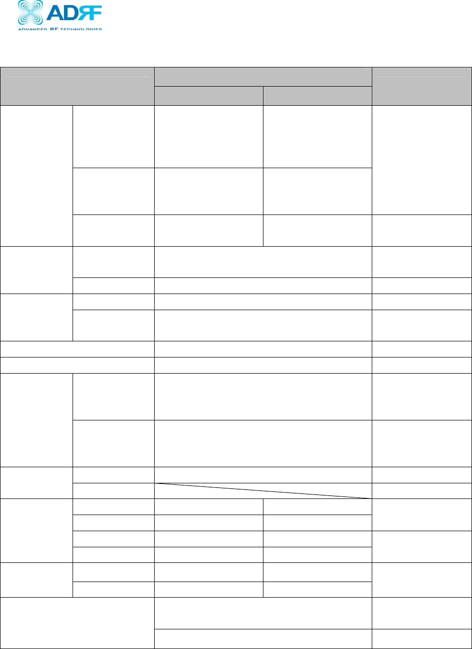
A.1 Electrical Specifications
Specifications
Parameters Downlink Uplink Remark
Cellular
A band
[(A+A”)=A+A’
]
869.0~880.0 MHz
890.0~891.5 MHz
824.0~835.0 MHz,
845.0~846.5 MHz
Cellular
B band
(B+B’)
880.0~890.0 MHz
891.5~894.0 MHz
835.0~845.0 MHz,
846.5~849.0 MHz
Configurable
Frequency
PCS 1930.0~1990.0
MHz
1850.0~1910.0
MHz
Cellular A(A+A”) + A’ or B + B’
(Configurable)
A’ or B’
spectrum on/off
Sub Band
Filtering PCS 5, 10 or 15 MHz BW (Tunable) contiguous band
Cellular >45dBc@±2MHz from the sub-band edge A,B
Roll off PCS >45dBc@±1.5MHz from the sub-band
edge.
Spurious Emissions 3.6 and 4.5 of [1], 3.8 and 4.4 of [2]
Radiated Spurious Emissions Part15.109, part 22.917, part24.238
Cellular 43+10log(p)dB or 26dB (greater of the
two) P : Maximum Output( W)
RBW 100 KHz or
1% of Emission
BW
Out of band
emissions
[3] PCS 43+10log(p)dB or 26dB (greater of the
two) P : Maximum Output (W)
RBW 1 MHz or
1% of Emission
BW
Downlink -105~-55dBm(EIRP)
Input Uplink
Cellular ≤ +20 dBm ≤ +17 dBm
PCS ≤ +20 dBm ≤ +17 dBm EIRP
Cellular ≤ +15 dBm ≤ +10 dBm
Output
PCS ≤ +18 dBm ≤ +12 dBm
Repeater
Only
Cellular 72 ± 2 dB 72 ± 2 dB
Gain PCS 81 ± 2 dB 81 ± 2 dB
Repeater
Only
≤ ±1.5dB across the Cellular and PCS
bands Typ: ±1.25
Gain flatness
≤ ±2dB at all temperature range
Verizon Wireless MPE25K RF Repeater
User Manual V0.3
Advanced RF Technologies, Inc. Proprietary Document 39/59
Cellular ≥ 30 dB Gain Control
Range PCS ≥ 30 dB
Cellular - 5 ~ + 15 dBm - 10 ~ + 10 dBm AGC Setting
Range PCS - 2 ~ + 18 dBm - 8 ~ + 12 dBm
Repeater
Only
EVDO Gain Offset -3 ~ +3dB, @ 0.5 dB Step
Cellular ≤ 8.5dB @ Max Gain
≤ 9.5dB @ Min Gain
≤ 7.0dB @ Max Gain
≤ 8.0dB @ Min Gain Repeater Only
Noise Figure
PCS ≤ 7.5dB @ Max Gain
≤ 8.5dB @ Min Gain
≤ 7.0dB @ Max Gain
≤ 8.0dB @ Min Gain Repeater Only
PCS ≤ 5 us
Delay Cellular ≤ 5 us
Phase error 3° RMS
Frequency
error ± 300 Hz for Cellular, ± 150 Hz for PCS
Magnitude
error < 5%
Rho factor > 0.912
Signal
Quality
IQ imbalance < 0.35%
VSWR <1:1.5 Input ports
[1] TIA/EIA-98-F, “Recommended Minimum Performance Standards for CDMA2000 Spread Spectrum
Mobile Stations”
[2] TIA/EIA-97-F, “Recommended Minimum Performance Standards for CDMA2000 Spread Spectrum Base
Stations”
[3] FCC CFR Title 47, part22 for Cellular, part24 for PCS
A.2 General Specifications
Parameters Specifications Remark
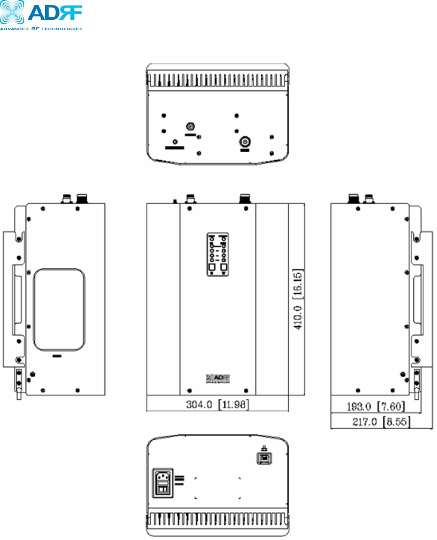
Dimension ( W × D × H ) 304×410×193mm (11.98 × 16.15 × 7.6 inches )
Weight( lbs ) 18.5 Kg ( 40.78 lbs )
Storage -4 ~ 158°F -20 ~ +70°C
Temperature
Operating 14 ~ 122°F -10 ~ +50°C
Humidity 5 ~ 85%, non condensing
AC power 100~120 VAC, 50~60 Hz
Power Consumption ≤ 90 W (PCS + Cellular )
Water IP40
Wireless Modem 3G Modem
Local RJ45 (DHCP)
NMS
Remote SNMP
Verizon Wireless MPE25K RF Repeater
User Manual V0.3
Advanced RF Technologies, Inc. Proprietary Document 40/59
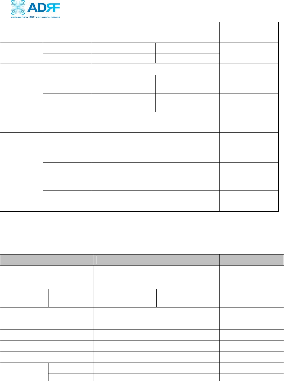
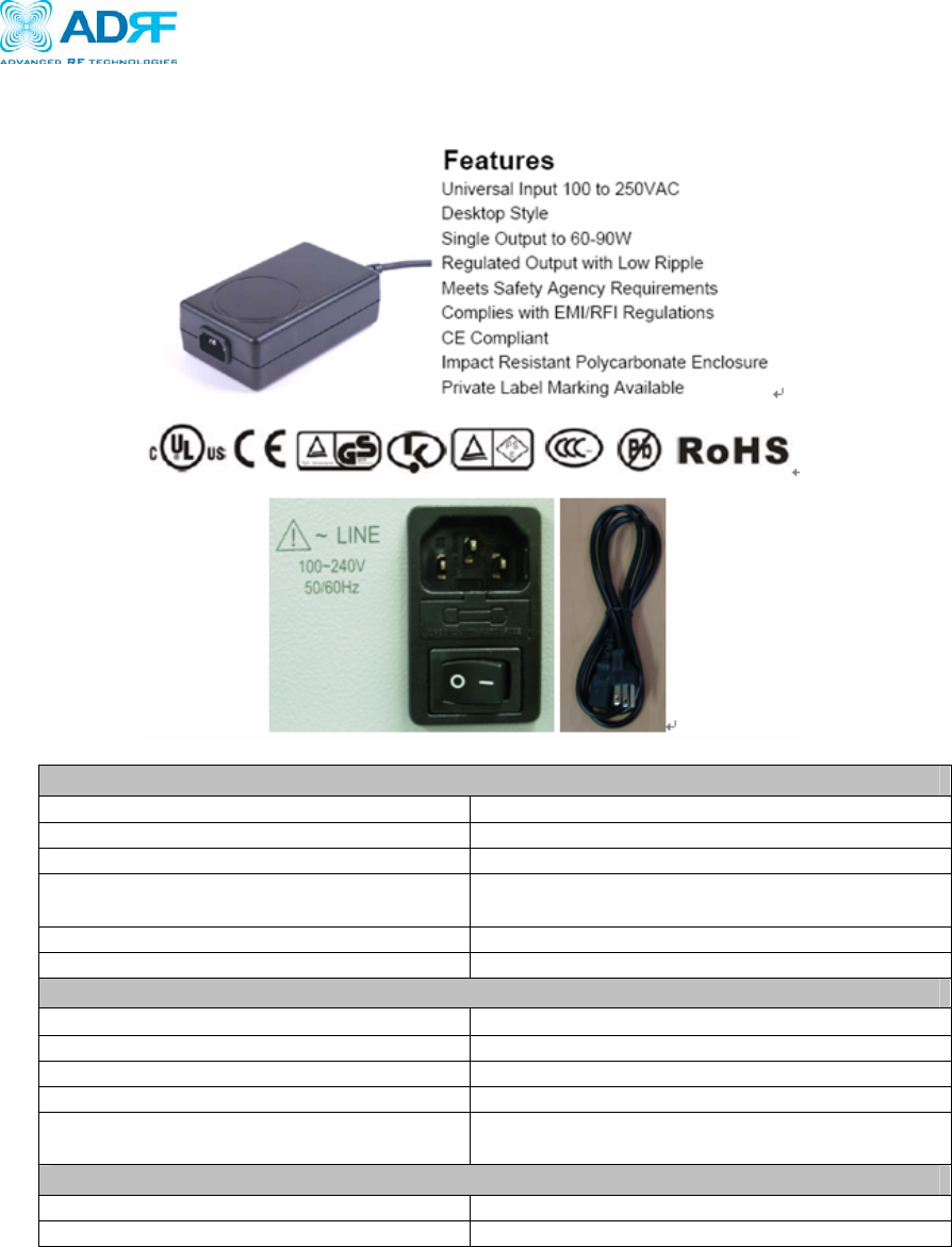
A.3 Power Supply Specifications
Input
Voltage 100 to 250VAC, ±10%
Line Frequency 47 to 63Hz
Current 2.0A max at 90VAC Input
Protection Internal Primary Current Fuse
Inrush Limiting
Power Factor Correction Complies with EN61000-3-2 and EN61000-3-3
Configuration Inlet Type: IEC320-C14, C18
Output
Combined Line and Load Voltage Regulation ±1% (excluding cord)
Ripple 1% Vp-p max.
Transient Response 0.5ms for 50% load change Typ.
Hold-up Time 16ms min. Over entire input range
Protection Foldback Over current
Short Circuit Protection
Safety Approvals
Agency Listings UL60950-1. TUV/IEC EN60950-1
EMC:EN55022/55024/61000, K60950-1
Verizon Wireless MPE25K RF Repeater
User Manual V0.3
Advanced RF Technologies, Inc. Proprietary Document 41/59
A.4 Antenna Specifications
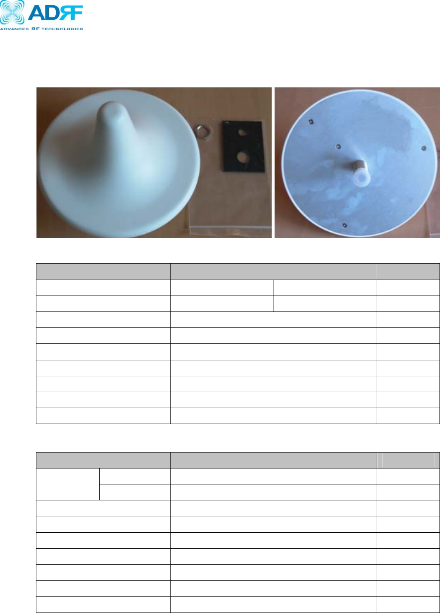
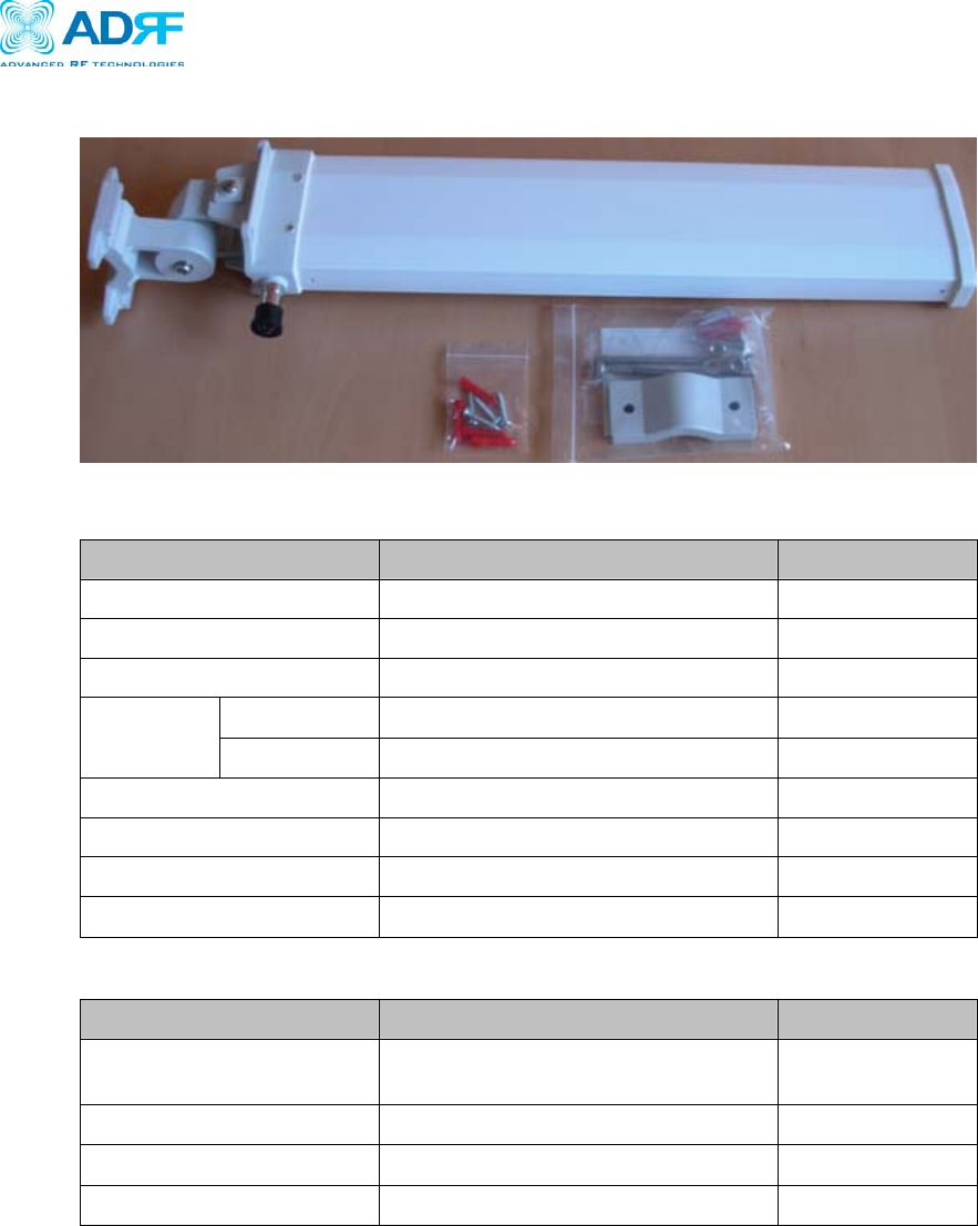
A.4.1 Server Antenna
z Electrical Specifications
Parameters Specifications Remarks
Frequency Range 824 ~ 894 MHz , 1920 ~ 2170 MHz
Gain 2 dBi (Min) 4 dBi (Min)
VSWR ≤ 2:1
Hori, Beam Width Omni
Polarity Vertical
IMD ≥ 165 dBc
Connector N type, Female
Maximum Power Rating 20 Watt
Impedance 50 Ohms
z Mechanical Specifications
Parameters Specifications Remarks
Diameter 7.244 inches ( 184 mm )
Dimension Height 4.134 inches ( 105 mm )
Weight 0.85 lbs (390 g)
Color White
Radome ASA Plastic
Polarity Vertical
Connector N type, Female
Maximum Power Rating 20 Watt
Impedance 50 Ohms
Verizon Wireless MPE25K RF Repeater
User Manual V0.3
Advanced RF Technologies, Inc. Proprietary Document 42/59
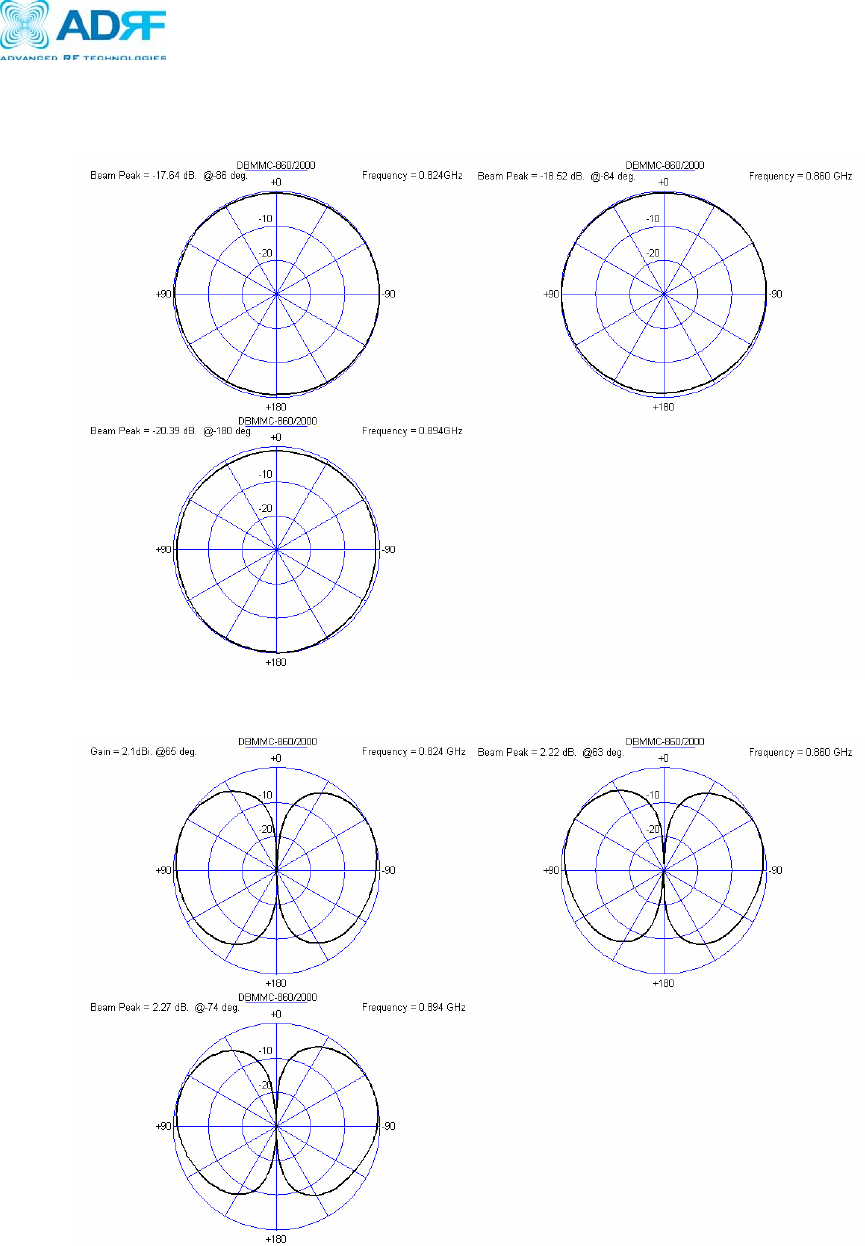
z Beam Patterns
- CDMA Horizontal Beam Pattern
- CDMA Vertical Beam Pattern

Verizon Wireless MPE25K RF Repeater
User Manual V0.3
Advanced RF Technologies, Inc. Proprietary Document 43/59
- PCS Horizontal Beam Pattern
- PCS Vertical Beam Pattern
Verizon Wireless MPE25K RF Repeater
User Manual V0.3
Advanced RF Technologies, Inc. Proprietary Document 44/59
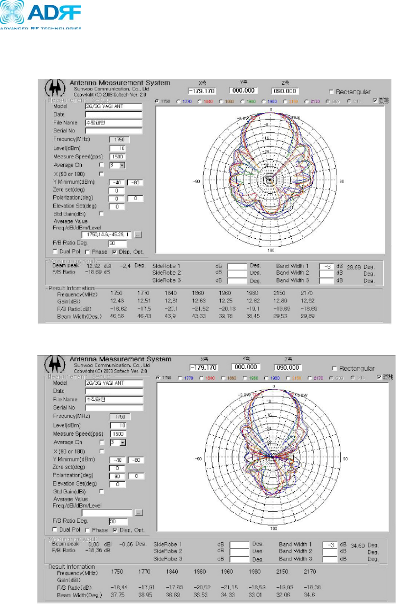
A.4.2 PCS Donor Yagi Antenna
z Electrical Specifications
Parameters Specifications Remarks
Frequency Range 1750 ~ 2170 MHz
Gain ≥ 12 dBi (Min)
VSWR ≤ 1.3:1
H ≥ 28° 29~46
Beam
Width V ≥ 34° 34~37
F-B Ratio ≥ 15 dB
IMD ≥ 165 dBc
Maximum Power Rating 50 Watt
Impedance 50 Ohms
z Mechanical Specifications
Parameters Specifications Remarks
Dimension 4.212 × 3.228 × 19.685 inches
( 107 × 82 × 500 mm )
Weight 3.307 lbs ( 1.5 Kg )
Radome Copper Al, PCB, ASA
Connector N type, Female
Verizon Wireless MPE25K RF Repeater
User Manual V0.3
Advanced RF Technologies, Inc. Proprietary Document 45/59
z Test Results
- PCS Horizontal Beam Pattern
- PCS Vertical Beam Pattern
Verizon Wireless MPE25K RF Repeater
User Manual V0.3
Advanced RF Technologies, Inc. Proprietary Document 46/59
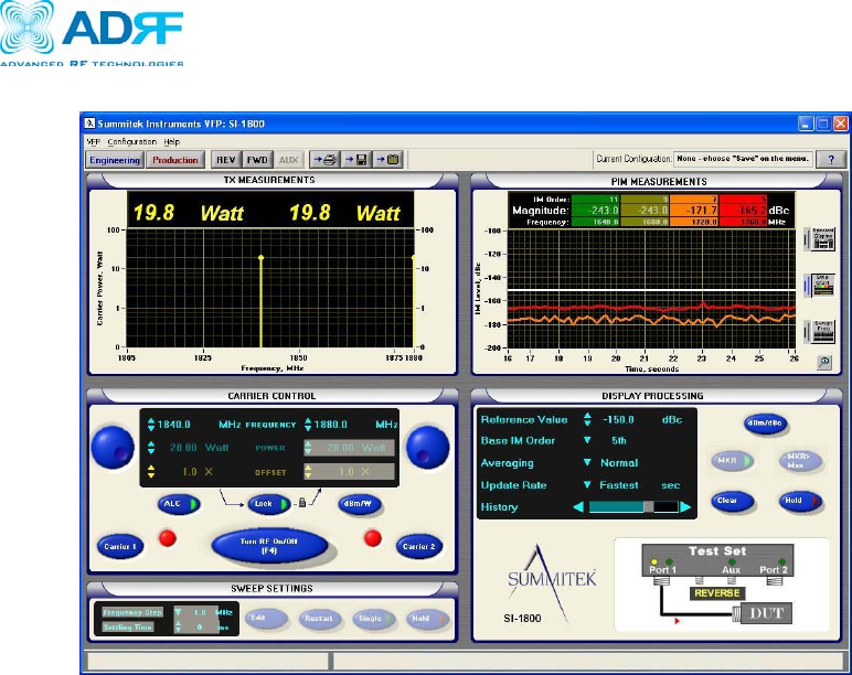
- PCS IMD Test
Verizon Wireless MPE25K RF Repeater
User Manual V0.3
Advanced RF Technologies, Inc. Proprietary Document 47/59
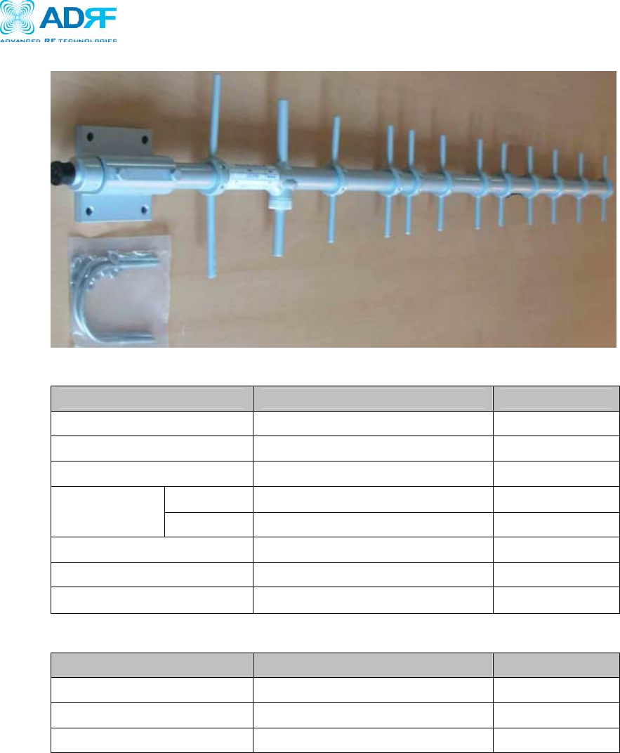
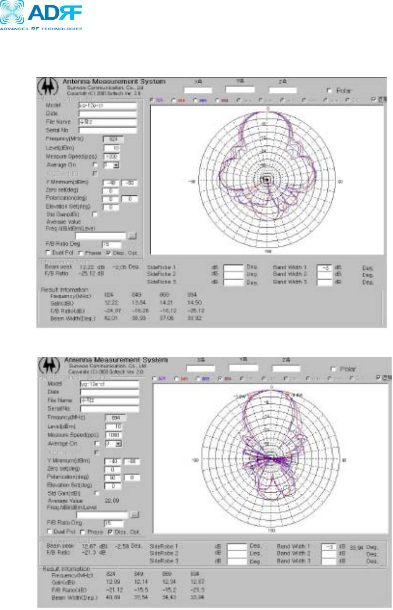
A.4.3 Cellular Donor Yagi Antenna
z Electrical Specifications
Parameters Specifications Remarks
Frequency Range 824 ~ 894 MHz
Gain ≥ 12 dBi (Min)
VSWR ≤ 1.3:1
H ≥ 35° 33~42
Beam Width V ≥ 32° 33~40
F-B Ratio ≥ 15 dB
Maximum Power Rating 50 Watt
Impedance 50 Ohms
z Mechanical Specifications
Parameters Specifications Remarks
Dimension( length ) 49.217 inches (1250 mm )
Weight 2.511 lbs ( 2.5 Kg )
Connector N type, Female
Verizon Wireless MPE25K RF Repeater
User Manual V0.3
Advanced RF Technologies, Inc. Proprietary Document 48/59
z Beam Patterns
- Cellular Horizontal Beam Pattern
- Cellular Vertical Beam Pattern
Verizon Wireless MPE25K RF Repeater
User Manual V0.3
Advanced RF Technologies, Inc. Proprietary Document 49/59
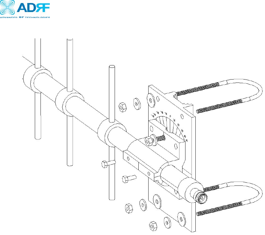
z Tilt Bracket for Cellular Yagi Antenna
Verizon Wireless MPE25K RF Repeater
User Manual V0.3
Advanced RF Technologies, Inc. Proprietary Document 50/59
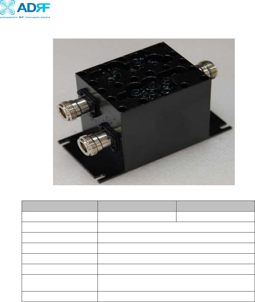
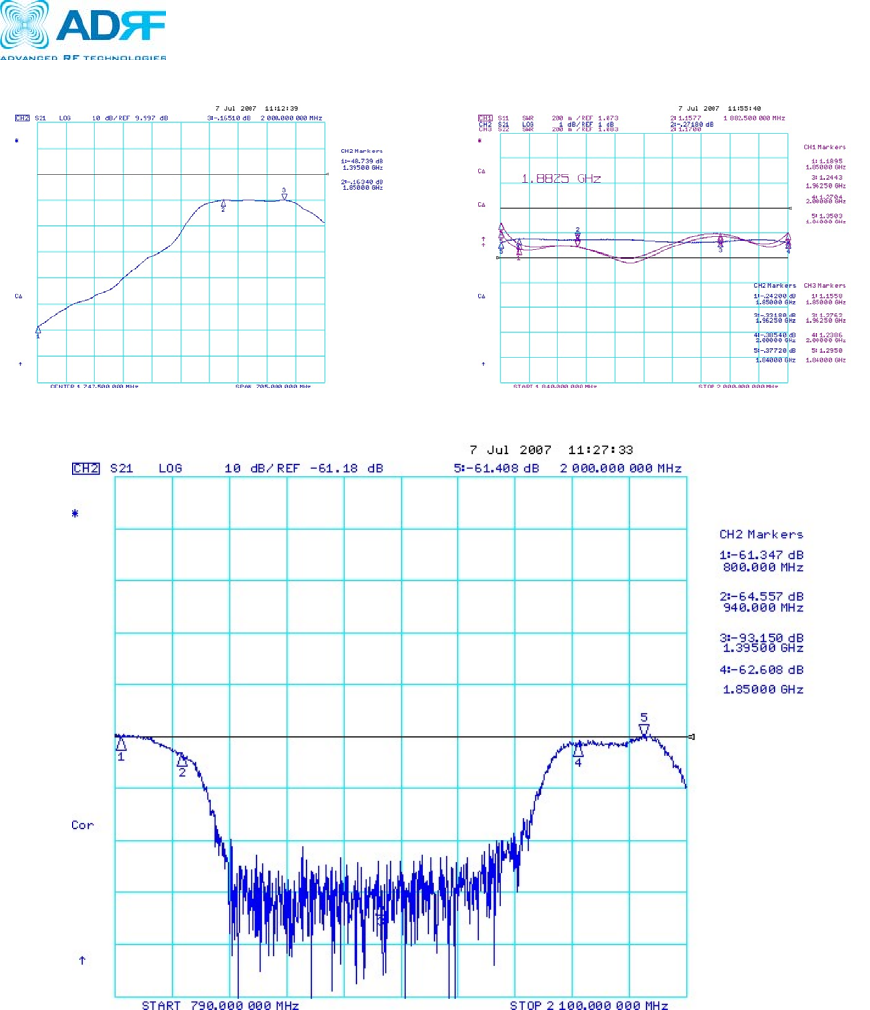
A.5 Diplexer Module Specifications
z Electrical Specifications
Type Cellular (Low Port) PCS (High Port)
Frequency 800 ~ 940MHz 1.84 ~ 2GHz
Ripple ≤ -0.5dB
Loss ≤ -1.0 dB
VSWR ≤ 1.4 : 1
Impedance 50 Ohms
Isolation ≥ -55 dB
Maximum Power
Rating 50 Watt
Dimension 1.96*3.93*2.55 inches ( 50*100*65 mm)
Verizon Wireless MPE25K RF Repeater
User Manual V0.3
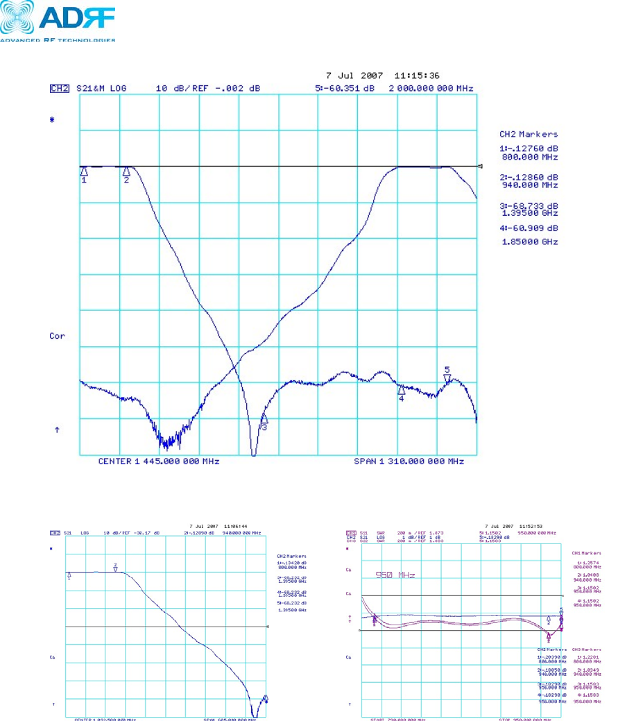
Advanced RF Technologies, Inc. Proprietary Document 51/59
- Full Band
- Cellular
Verizon Wireless MPE25K RF Repeater
User Manual V0.3
Advanced RF Technologies, Inc. Proprietary Document 48/59
- PCS
- Port Isolation
Verizon Wireless MPE25K RF Repeater
User Manual V0.3
Advanced RF Technologies, Inc. Proprietary Document 49/59
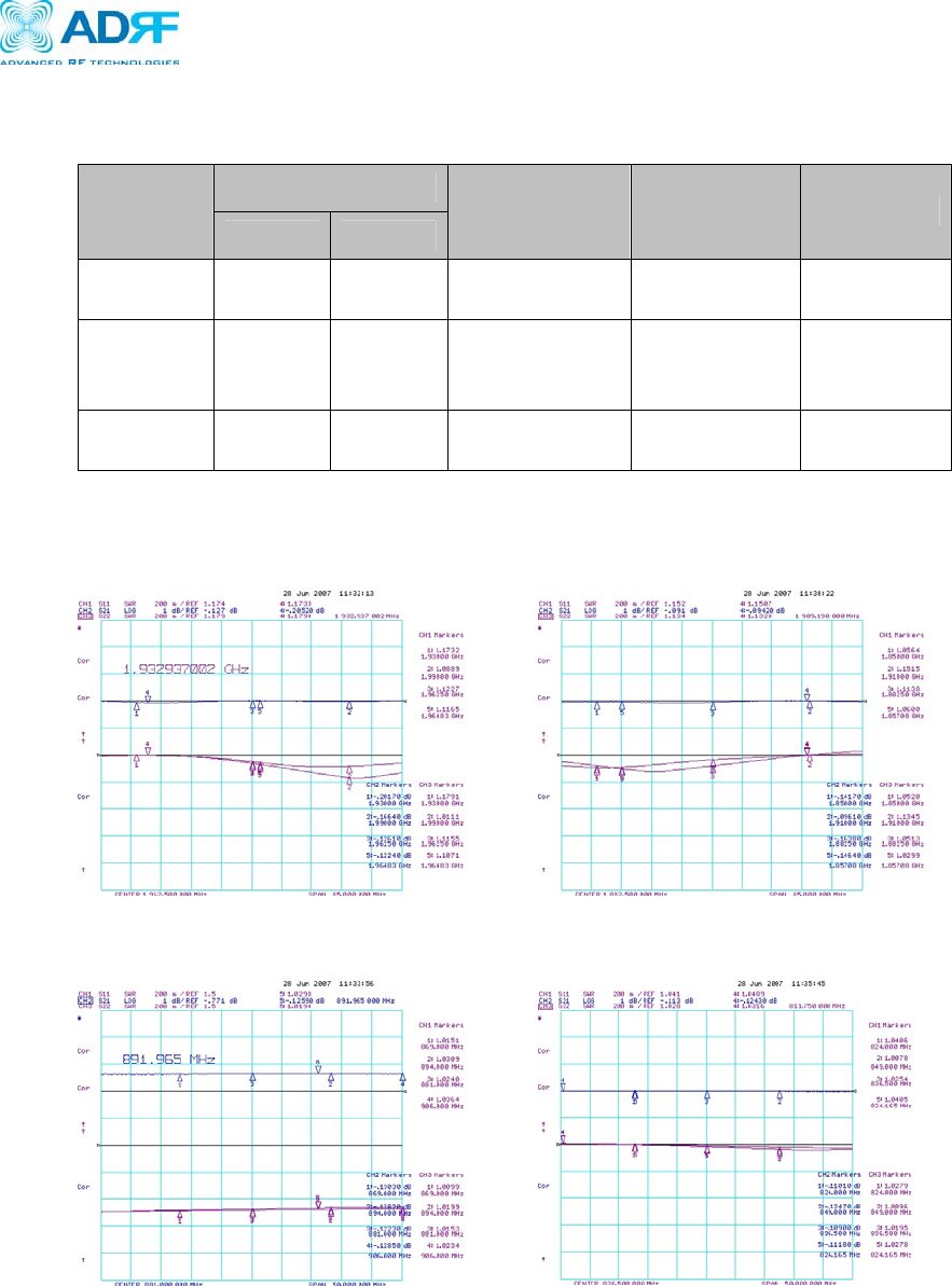
A.6 Cable Specifications
z Coaxial Cable Specifications
Loss
Length
Cellular PCS
Weight Connector Remark
3 ft (1M) ≤ 0.2 dB ≤ 0.3 dB ≤0.485 lb
(220g) / EA N-M To N-M Donor To
Diplexer
150 ft
(45.71M) ≤ 4 dB ≤ 5.5 dB
≤22.31 lb
(10.12 Kg) /
EA
N-M To N-F Diplexer To
Repeater
30 ft
(9.14M) ≤ 1.2 dB ≤ 1 dB ≤4.60 lb
(2.09 Kg) / EA N-M To N-M Server To
Repeater
z Test Results for 3 ft (1M) Cable
- PCS
- Cellular
Verizon Wireless MPE25K RF Repeater
User Manual V0.3
Advanced RF Technologies, Inc. Proprietary Document 50/59
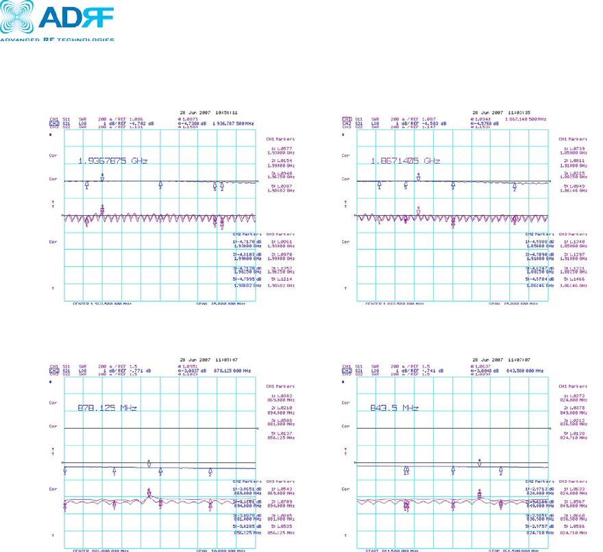
z Test Results for 30 ft (9.14M) Cable
- PCS
- Cellular
Verizon Wireless MPE25K RF Repeater
User Manual V0.3
Advanced RF Technologies, Inc. Proprietary Document 51/59
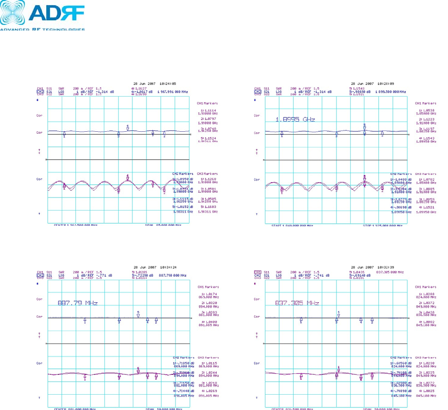
z Test Results for 150 ft (45.71M) Cable
- PCS
- Cellular
Verizon Wireless MPE25K RF Repeater
User Manual V0.3
Advanced RF Technologies, Inc. Proprietary Document 52/59
Appendix B: Mechanical Drawing
Verizon Wireless MPE25K RF Repeater
User Manual V0.3
Advanced RF Technologies, Inc. Proprietary Document 53/59
Appendix C: ADRF-25K Overview
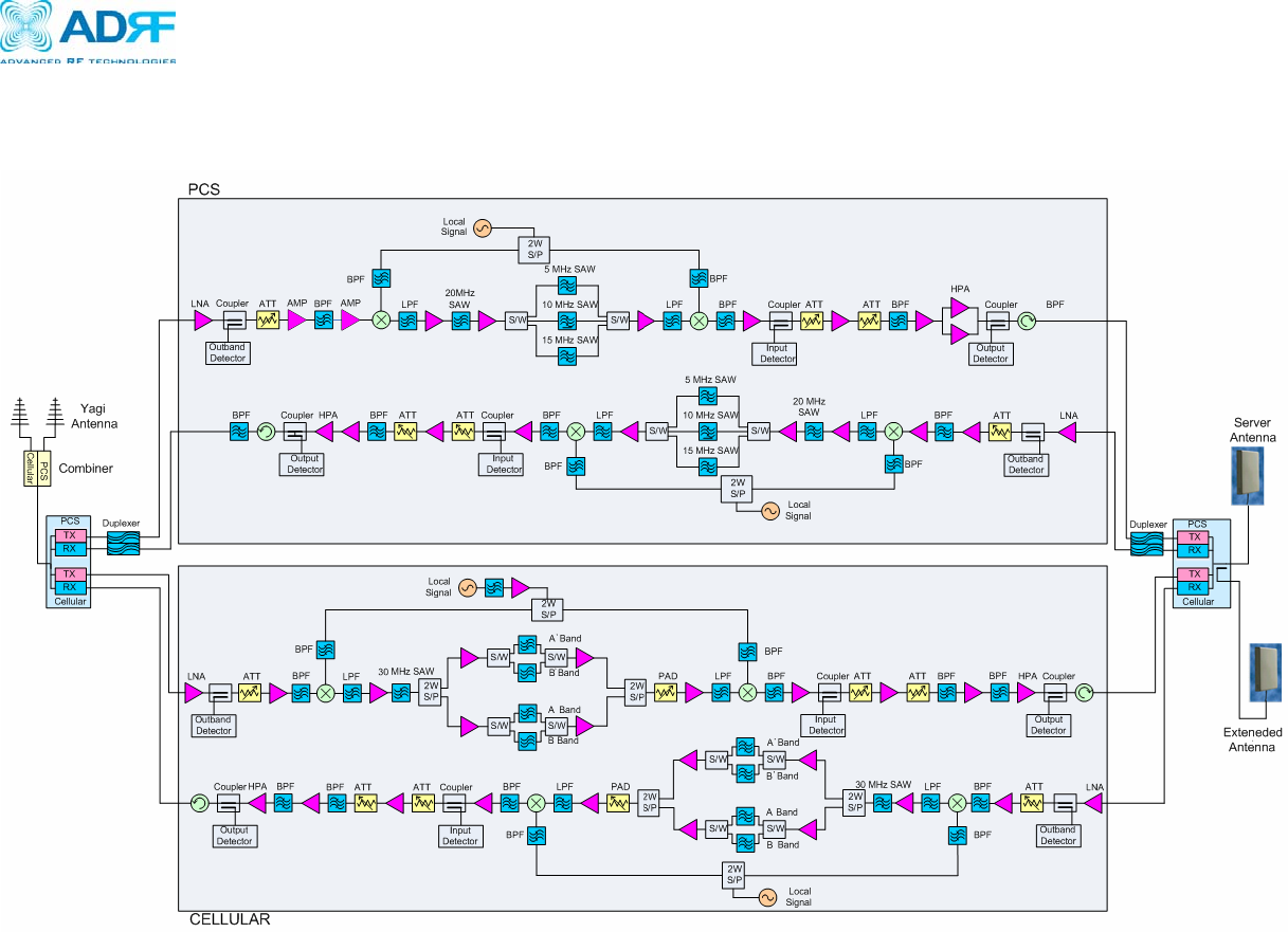
C.1 Block Diagram
Verizon Wireless MPE25K RF Repeater
User Manual V0.3
Advanced RF Technologies, Inc. Proprietary Document 54/59
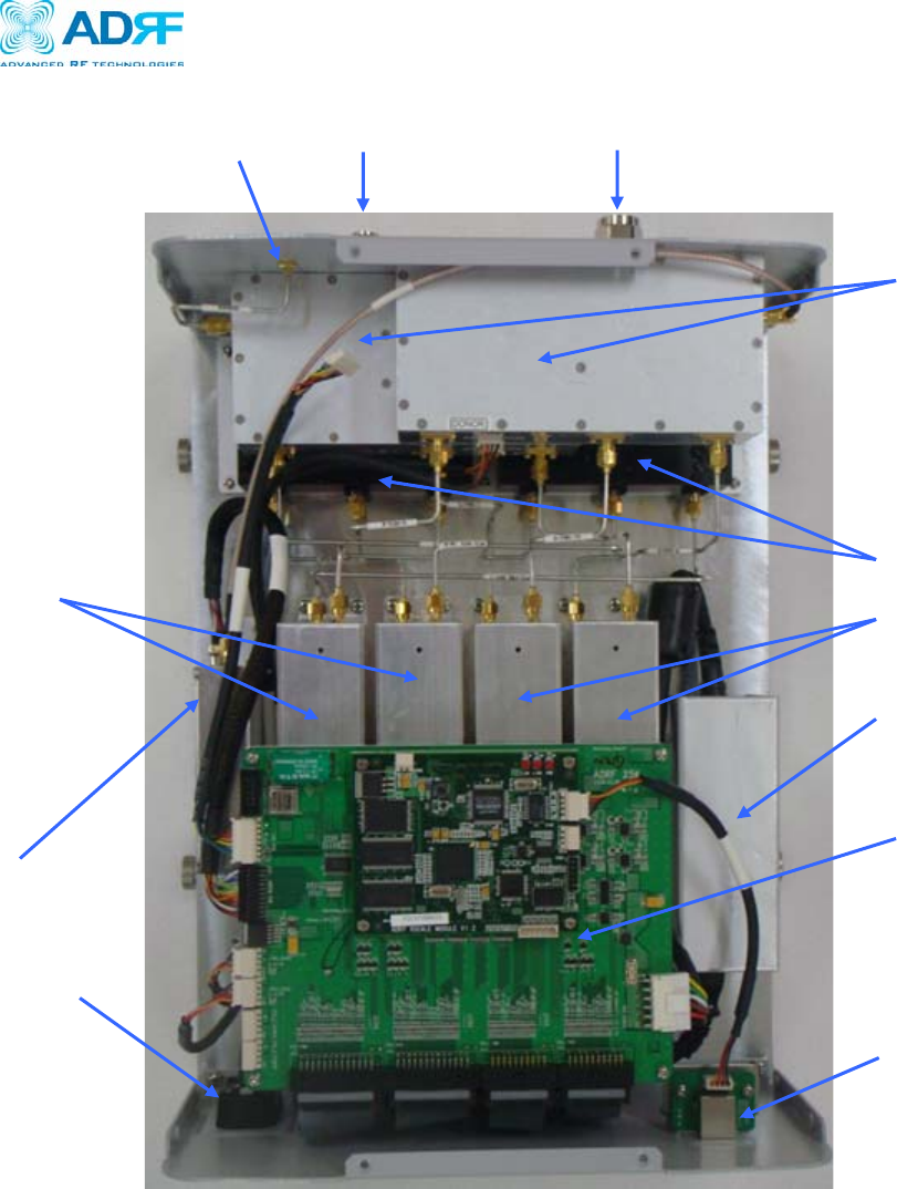
C.1 Components
PCS UP/Down Converte
r
Cellular UP/Down
DHCP Sub Board
Power Supply
Controller
Modem Module
Triplexer
Donor Port Server1 Port Server2 Port
AC Por
t
PCS Duplexer

Verizon Wireless MPE25K RF Repeater
User Manual V0.3
Advanced RF Technologies, Inc. Proprietary Document 55/59
Power Supply
It provides DC power to each module within the repeater.
Controller
It is responsible for monitoring the status of each module and controls the
parameters.
PCS Up / Down Converter Module
The downlink RF signal that enters through the cavity filter is converted to IF
frequency, which is later converted back to RF frequency through SAW filtering.
Cellular Up / Down Converter Module
The downlink RF signal that enters through the cavity filter is converted to IF
frequency, which is later converted back to RF frequency through SAW filtering.
PCS Duplexer
It consists of two BPFs (band-pass filters): PCS TX (1930 ~ 1990 MHz) & RX
(1850 ~ 1910 MHz)
Triplexer
Combines Cellular and PCS signals. It consists of three BPFs (band-pass filters):
PCS and Cellular TX and RX.
Modem Module
Contains the CDMA 2000 modem (Kyocera M200).